1
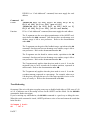
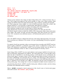
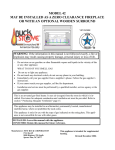
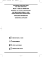
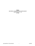
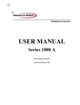
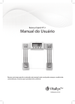
ASIs Drive Electronics for Piezo Top-Plate ADEPT’s Features: Closed loop operation with strain gauge feedback. Auto strain gauge calibration on startup. Accepts inputs from TG-1000 (digital) or external (analog) sources. Nanometer precision with low noise and drift. Figure 1 ADEPT Card Introduction ADEPT is an add-on module that extends the TG-1000 controller’s capability to control piezo top-plate. The user can position the piezo top-plate through TG-1000s serial commands or manual inputs like the knob, or through an external signal source. TG-1000 can support multiple ADEPT cards. ADEPT can operate either in open loop or closed loop mode. In closed loop mode, it uses high sensitivity semiconductor strain gauge as sensors to position the piezo top-plate with nanometer precision and transient time less than 25ms. ADEPT card performs self test and calibration on startup, so the system maintains calibration. Connectors 1. PiezoTop-plate Connector 2. Sensor Out 3. External Input 4. CRISP (optional) 1 2 4 3 Figure 2 TG-1000 Connections External Input and Output Apart from using the ADEPT card to position the piezo top-plate through TG-1000, this card can also get positioning information through 0-10V analog signal. PAGE 1 When the controller is set to external input mode (using the PM [axis] command, ADEPT positions the piezo top-plate based on the voltage applied to EXT IN or external input. The analog signal should be between 0 to 10 volts, where 10 represents lower limit, and 0 volts represents higher limit. For every 1 volt change, the piezo top-plate changes the piezo range. Example, if it’s a 150um piezo top-plate 1 volt represents 15um, 0.1 volt represents 1.5um. We recommend that frequency of the signal be kept less than 10Hz for long moves, so as to give the piezo top-plate time to settle down and come to a complete stop. Sensor Out is a 0 to 10 volt analog signal that corresponds to position of the piezo top-plate. It is a buffered output of the strain gauge sensors. Command Set Apart from the regular axis commands like MOVE, MOVREL, ZERO, INFO (refer to TG-1000 Programming section) here are some ADEPT specific commands. Most users do not need to use these commands unless configuration are changed or problems are encountered. As explained in the TG-1000 programming manual, TG-1000 high level or H command set is classified as “Axis-Specific”, “Card-addressed” and “Broadcast” commands. For Axis-Specific commands TG-1000 Comm automatically dispatches incoming commands from the host to the appropriate card(s) via the backplane communication bus. However for “Card-addressed” commands, the host needs to specify the card the command is intended for by supplying the card address in front of the command. On start TG-1000 sends to the host thru serial all the available cards in the system and their address. For example, here is the startup response of a TG-1000 system with one dual axis card and 2 ADEPT cards ................................................................ At 30: Comm v1.5 TIGER_COMM May 07 2013:15:42:05 At 31: X:XYMotor,Y:XYMotor v2.4 STD_XY Jun 11 2013:17:00:12 At 32: Z:Piezo v2.4 ADEPT_PIEZO Jun 11 2013:17:05:00 Joystick ready. System ready. : Below is a small list of ADEPT specific commands and they type. For the complete list and more info on usage of commands refer to TG-1000 programming manual. Command String PR PM PAGE 2 Command Type Axis-Specific Axis-Specific PG PSG PZINFO PZ PZC SS MOVE MOVREL ZERO Axis-Specific Axis-Specific Card-addressed Card-addressed Card-addressed Card-addressed Axis-Specific Axis-Specific Axis-Specific So if the host wants to run auto calibration on piezo top-plate on Z axis, host would issue the serial command 2PZC to TG-1000 as PZC is a Card-addressed command. If you would like to put Z axis in external input mode then host would issues PM Z=1. To save this setting in nonvolatile memory host would issue 2SS Z. Command: Format Function PR PR [axis]=[0 to 7] PR is used to set the piezo travel range. It is an Axis specific command. Setting is automatically saved in the non-volatile memory. Will need a system RESET or RESTART for setting to take effect. PR [Axis Piezo Range in microns Name] = Command: Format Function PAGE 3 1 50 2 100 3 150 4 200 5 300 6 350 7 500 PM PM [axis]=[0 to 4] PM command sets the ADEPT card in various modes, Open Loop, Closed loop, MS2000 input and External input. It is an Axis specific command. PM [axis] = Mode of Operation 0 TG-1000 (default) 1 External input, Closed Loop 2 TG-1000 input, Open loop 3 External input, open loop 4 Same as Mode 0 except adds tunable speedup algorithm (v2.8+) input, Closed loop In Open Loop mode, a set voltage is applied to the piezo and the feedback from strain gauge is ignored. Useful during system calibration. In Closed Loop mode, the voltage applied to the piezo is adjusted according to the feedback coming from the strain gauges. This is the default mode of operation. TG-1000 input, in this mode the TG-1000 controller generates the positioning input for the piezo top-plate. This is the default mode of operation. In External input mode, the piezo top-plate is positioned according to 0 to 10V analog signal provided by the user. Every one volt change moves the piezo the range. We recommend that frequency of the signal be kept less than 10Hz for long moves, to give the piezo top-plate sufficient time to settle and come to a complete stop. Mode 4 is TG-1000 input and closed loop, but a tunable speedup algorithm is applied to moves. The tuning is done by the user setting two parameters using the PZ command. The user sets up an intentional overshoot amount and a maximum time for the overshoot to be applied. When a move is initiated, the piezo moves towards the overshoot position until the maximum time is reached or else until the measured position (using the strain gauge) has reached the halfway point between the previous position and the intended (non-overshoot) position. Subsequently the command signal to the intended position is applied. Experimentally this can reduce settling time by 10-60%. The overshoot amount is set using [#Addr]PZ T, expressed in percent. The maximum time to move towards the overshoot position is set using [#Addr]PZ F, expressed in milliseconds. Mode 4 does not function PAGE 4 with CRISP-enabled firmware. The modes will revert back to default state, i.e. TG-1000 input with Closed Loop when system is powered off. Use the [#Addr]ss z command to save your preference. The settings set with this command can also be done with PZ commands. One does not have an advantage over another; usage is left to user preference. Command: Format Function PG PG [axis]=[25 to 5101] (pre v2.84) PG [axis]=[1 to 255] (v2.84 and above) PG command is used to set the gain of the feedback stage. The setting is stored in a non volatile memory on the ADEPT board. This is one of the settings that is automatically picked during long auto calibration. Please refer the calibration section for its usage. It is an Axis specific command. Setting is automatically saved in the non-volatile memory. The settings set with this command can also be done with PZ commands. One does not have an advantage over another; usage is left to user preference. Pre v2.83 a formula was used to convert 25-5101 to b bit 255. We had rounding off issues and such. We removed the formula so now user can enter the setting directly and thus have more control. Command: Format Function PSG PSG [axis]=[1 to 255] PSG command argument sets the zero adjust potentiometer of the ADEPT card. Only values between 1 and 255 are accepted. The setting is stored in a non volatile memory on the ADEPT board. This is one of the settings that are automatically picked during both long and short auto calibration. Please refer the calibration section for its usage. The settings set with this command can also be done with PZ commands. One does not have an advantage over another; usage is left to user preference. Command: PZC [#Addr]PZC X=[0 or 1] Y=[0,1,2,3] Z=[1 to 100] Format F=[1 to 100] ,or [#Addr]PZC Function PZC when entered alone runs the auto calibration routine that sets PAGE 5 various internal parameters for optimal operation of the piezo top-plate. :A is returned on completion, :N-5 is returned if the routine failed. PZC is a “Card-Addressed” command; host must supply the card address. X argument sets the auto calibration type to perform. 0 is for short calibration (default) i.e. only strain gauges offset is adjusted. While 1 is long calibration routine, with adjusts both strain gauge offset and the feedback gain. You will need a length gauge to run the full calibration routine. Ss z command is not applicable, settings will revert back to default when controller restarts. Note: Long calibration is not implemented for ADEPT card with TG-1000. Usage will end in an error. Y argument sets the axis index to which the length gauge is assigned. Default is 0 i.e. X index in a 4 axis build. Ss z command not applicable, settings will revert back to default on controller restart. Z argument sets the delay between routine runs, default is 35 i.e. 35ms. Units are in milliseconds. [Addr#]SS Z command not applicable, settings will revert back to default on controller restart. F argument sets the position where controller moves the piezo top-plate before adjusting the strain gauge offset. Accepts values between 1 to 100, units are %, default is 50 i.e. middle of the piezo range. Ss z command is applicable, settings will be saved between controller restarts. Please use HALT command to stop a running calibration routine; else the routine will leave incorrect settings on the ADEPT card. Command: Format Rely Function: PAGE 6 PZINFO [#Addr]PZINFO Voltages @ Pos1> HV : 147 V Sout : 4 V Pzout: 65 V I2C Check> DAC[OK] SWITCH[OK] DigPot[OK] DigPot> Sgoffset: 110 Gain: 96 Closed Loop TG-1000 IN SG Offset [OK] When issued TG-1000 replies with all relevant ADEPT card settings to aid in trouble shooting. Please refer to the Troubleshooting section for explanation of the message. PZINFO is a “Card-Addressed” command; host must supply the card address. Command: Format Function PZ [#Addr]PZ X=[1 to 255] Y=[25 to 5101] Z=[0 to 3] F=[0 to 100] T=[0 to 500] (pre v2.83) [#Addr]PZ X=[1 to 255] Y=[1 to 255] Z=[0 to 3] F=[0 to 100] T=[0 to 500] (v2.83 and above) PZ is a “Card-Addressed” command; host must supply the card address. The X argument sets the zero adjust potentiometer of the ADEPT card, equivalent to the PSG command. One does not have an advantage over another; usage is left to user preference. Refer to the documentation under PSG. The Y argument sets the gain of the feedback stage, equivalent to the PG command. One does not have an advantage over another; usage is left to user preference. Refer to the documentation under PG. The Z argument sets the board in various modes, equivalent to the PM command. One does not have an advantage over another; usage is left to user preference. Refer to the documentation under PM. The F argument only applies when the piezo mode is set to 4. It sets the maximum time to move towards the overshoot position, expressed in milliseconds. Refer to the documentation under PM. The T argument only applies when the piezo mode is set to 4. It sets the overshoot amount, expressed as a percentage. For example, when set to 100 the piezo will begin the move as if the target position is twice as far away as it really is. Refer to the documentation under PM. Troubleshooting On startup if the axis with piezo top-plate comes up as disabled with either a COD error of 140 or 141, it indicates one of the startup self test for the ADEPT card has failed. Use the PZINFO command to further investigate. If you’re noticing any odd behavior, the PZINFO command is a good way to debug the error. When this serial command is issued, ADEPT performs a series of test and returns the result that looks like this: Voltages @ Pos1> HV : 147 V PAGE 7 Sout : 4 V Pzout: 65 V I2C Check> DAC[OK] SWITCH[OK] DigPot[OK] DigPot> Sgoffset: 110 Gain: 96 Closed Loop TG-1000 IN SG Offset [OK] Voltage @ Pos1 indicates the Voltage on High Voltage Rail as HV, Voltage on Sensor Out as Sout and Voltage being applied to the piezo top-plate as Pzout at the current position. High Voltage rail should always be in high 140s and more, if not it indicates a problem on the board. I2C Check pings the various digital Ics on the ADEPT board and returns OK or BAD. OK indicates that the IC is powered and is communicating. BAD indicates a problem. DigPot returns the current calibration settings, strain gauge offset and feedback gain. Next it indicates whether the card is in open loop or closed Loop mode. Then it displays the current source of piezo top-plate position. TG-1000 IN or EXT IN. SG Offset is a quick routine to checks the validity of the strain gauge offset setting, and returns OK or BAD. This routine will only check the strain gauge offset, and will not try to correct it. Issue a PZC command to run calibration routine; it will automatically pick the correct value. Calibration Note: All ADEPT boards are calibrated in the factory and undergo thorough testing. Users do not have to perform any calibration. This section is for your understanding of the piezo top-plate’s working. For optimal closed loop operation, when a strain gauged piezo top-plate and ADEPT board are paired together calibration is performed. Every piezo system is calibrated in factory, and a shorter self calibration is performed by ADEPT card on startup. Ideally users do not have to worry about calibrations, offsets etc. Here is a short description of what they involve. Strain Gauge Offset: ADEPT uses two semiconductor strain gauges installed in the piezo topplate in half bridge configuration for feedback. One strain gauge flexes as the top-plate moves while the other is installed in a non flexing position. As the top-plate moves up and down, the flexing strain gauge’s resistance relative to the unflexing strain gauge increases and decreases, the sensor conditioning circuit interprets this as a voltage. The strain gauge offset parameter is the setting for a digital potentiometer that adjusts the resistance of the unflexing strain gauge so that at a position of our choosing (set by PZC F command) it has the same resistance as the flexing strain gauge. This setting can be viewed and adjusted with PZ X serial command. It is automatically picked by the ADEPT controller during auto calibration routine, and also during the shorter self calibration routine on startup. When a PZINFO command is issued, among one of the check it runs is for the strain gauge offset and it returns a SG Offset [OK] or [BAD] PAGE 8 Feedback Gain: When the piezo top-plate moves, the strain gauge interprets this as the change in resistance. The feedback gain is the parameter that helps the sensor conditioning circuit interprets this change in resistance as a voltage, and then into distance moved. There is a known problem with the calibration routines when the user has changed the software limits on the piezo using SETUP or SETLOW command. This is especially likely if the limits have been set asymmetrically. Performance Electrical Performance Capable of Applying -24V to 150V to the Piezo actuators Maximum continuous output current of 13mA 11msec Transient Response time (10%-90%) for moves below 30% travel range with 600grams load. Characteristics Name PZ-2150 150um Piezo Travel Range (+- 5%) Piezo smallest move/resolution * 2.2nm Maximum Load for full range travel in Kilogram Transient Response time ** External Analog input(BNC) Maximum Input Frequency 2Kg PZ-2300 300um 4.5nm PZ-2500 500um 7.6nm 1Kg 1Kg 11 – 15 millisec 0 to 10 Volts 20 Hz *This is with ADEPT controller’s 16Bit DAC. User may improve this thru a high resolution signal generator, and the system operating in external input mode. ** Time took to travel 10%-90%, for moves below 30% travel range and with 600 grams load. PAGE 9 Transient Response Figure 3 the above graph shows the step/transient response of ASIs piezo top-plate for a 30um move. The rise time is 11msec. The above graph is the transient response of a 150um ASI piezo top-plate. Red waveform is the user commanded input or desired output. Green waveform is the actual piezo top-plate position interpreted from sensor out. Here it shows the piezo top-plate travel 30um with a rise time (10% to 90%) of 11 msec. The piezo top-plate was loaded with 600grams payload. We observed that the transient tends to increase for longer moves. Travel Range 30% 50% 70% 150um 11-12ms 10-12ms 13.5-17ms 300um 9 – 10.5ms 9 – 14.5ms 14.5 – 17ms 500um 10 – 14.5ms 26 – 30ms 33 – 45ms All values listed above are with 600grams load. Frequency Response In this test a sine wave of 2 Volt peak to peak and 5Vrms of varying frequency is applied thru external input and the response of the top-plate was interpreted on sensor out is observed and its amplitude is recorded. This is used to determine what the maximum possible input frequency is. Top-plate is loaded with 600grams payload. PAGE 10 0 1 10 100 1000 -2 Gain in dB -4 -6 Series1 -8 -10 -12 -14 Frequency in Hz Observation: As the moves come more frequently, the piezo top-plate may not have sufficient time to finish its move and settle in and the move is left incomplete. The above graph shows that over 10Hz or more that 10 commanded moves a second, there are a lot of incomplete moves and at 40Hz the top-plate only travels half the commanded distance. Top-plate Load capacity During testing we found the 150um can carry 2Kg load and the 300um and 500um can carry 1Kg load without any noticeable drop in performance. The Top-plates will continue to perform at high loads with some loss in performance like travel range, accuracy and repeatability. The maximum load we tested was 4Kg, at which point the top-plates lost 20% of their travels. Caution: Mass above 5Kgs may damage the top-plate. Always try to have the mass evenly distributed on the top-plate. Change log Last Updated 8/16/2010 4/25/2011 4/26/2011 5/26/2011 6/17/2011 9/13/2012 7/3/2013 11/5/2013 PAGE 11 Comments Rough Draft Updated the Performance section Performance section edited again Characteristic performance added Load and transient response performance data added. Branched from ADEPT user manual, Edited for Tiger ADEPT Formatting updated to match other manuals Added note about calibration failing if limits are changed 11/22/2013 3/6/2014 PAGE 12 Added documentation about new mode PM [axis]=4 Changed PZ Y=### / PG cmds now accepts Dig pot setting directly, 0-255