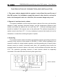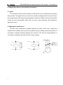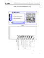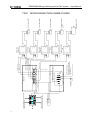
1
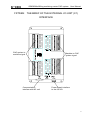
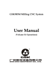
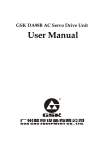
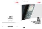
This user manual describes all proceedings concerning the
operations of this system in detail as much as possible. However, it is
impractical to give particular descriptions for all unnecessary or
unallowable system operations due to the manual text limit, product
specific applications and other causes. Therefore, the proceedings
not indicated herein should be considered impractical or unallowable.
This user manual is the property of GSK CNC Equipment Co.,
Ltd. All rights are reserved. It is against the law for any organization or
individual to publish or reprint this manual without the express written
permission of GSK and the latter reserves the right to ascertain their
legal liability.
GSK983Ma Milling machining center CNC system
User Manual
Preface
Your Excellency,
It’s our pleasure for your patronage and purchase of this GSK983Ma
Milling machining center CNC system made by GSK CNC Equipment Co.,
Ltd.
Safety Caution
Accident may occur by improper connection and operation!This
system can only be operated by authorized and qualified personnel.
Please carefully read this manual before using!
Refer to user manual issued by the manufacturer carefully before
installing, programming and operating this product, and the relative
operation should be performed based upon the user manual strictly.
II
GSK983Ma Milling machining center CNC system
User Manual
Security Responsibility
Security responsibility of the manufacturer
——Manufacturer should take responsibility for the design and structure danger
of the CNC system and the accessories which have been eliminated and/or
controlled.
——Manufacturer should take responsibility for the security of the CNC system
and accessories.
——Manufacturer should take responsibility for the offered information and
suggestions for the user.
Security responsibility of the users
——User should know and understand about the contents of security
operations by learning and training the security operations of the CNC
system.
——User should take responsibility for the security and danger because of
increasing, changing or modifying the original CNC system or accessory by
themselves.
——User should take responsibility for the danger without following the
operations, maintenances, installations and storages described in the
manual.
III
GSK983Ma Milling machining center CNC system
User Manual
This manual is reserved by final user.
We are full of heartfelt gratitude to you for supporting us in the use of
GSK’s products.
Chinese version of all technical documents in Chinese and English
languages is regarded as final.
IV
GSK983Ma Milling machining center CNC system
User Manual
CONTENT
THE PRECATION OF CONNECTION AND INSTALLATION ....................................................................... 1
ONE
NC UNIT INTERFACE LIST ................................................................................................................... 3
TWO
INTERCONNECTION FRAME FIGURE .............................................................................................. 4
THREE
THE CONNECTION BETWEEN NC UNIT AND GS2000T-CA1 SERIES DRIVE UNIT
(WITHOUT BRAKE) ............................................................................................................................................. 5
FOUR
THE CONNECTION BETWEEN NC UNIT AND GS2000T-CA1 SERIES DRIVE UNNIT
(WITH BRAKE) ..................................................................................................................................................... 6
FIVE
SIX
THE FULL-CLOSED CONNECTION WITH THE GRATING ............................................................ 7
THE CONNECTION BETWEEN NC UNIT AND DAP03 SPINDLE DRIVE UNIT ........................... 8
SEVEN
THE CONNECTION BETWEEN NC UNIT AND GS3000Y-NP2 SPINDLE SERVO DRIVE
UNIT ........................................................................................................................................................................ 9
EIGHT
THE CONNECTION BETWEEN NC UNIT AND SPINDLE FREQENCY-CONVERTER ........ 10
NINE
MACHINE OPERATOR PANEL INTERFACE ................................................................................... 11
TEN
THE CONNECTION BETWEEN NC UNIT AND OPERATION PANEL ......................................... 12
ELEVEN
THE CONNECTION BETWEEN EXTERNAL MPG AND OPERATION PANEL.................. 13
TWELVE
THE CONNECTION BETWEEN NC UNIT AND PC MACHINE ............................................. 14
THIRTEEN
THE CONNECTION METHOD OF THE Z AXIS BRAKE AND SYSTEM POWER-ON
CONTROL............................................................................................................................................................ 15
FOURTEEN
FIFTEEN
THE CONNECTION BETWEEN NC UNIT AND I/O UNIT ................................................. 16
THE BRIEF OF THE EXTERNAL I/O UNIT (X1) INTERFACE .............................................. 17
SIXTEEN THE CIRCUIT CONNECTION OF THE I/O UNIT (X1) INPUT/OUTPUT SIGNAL.............. 18
SEVENTEEN
I/O UNIT (X1) INPUT/OUTPUT POINT DEFINITION ....................................................... 19
EIGHTEEN
THE CONNECTION OF THE ZERO AND LIMIT SWITCH ................................................. 23
NINETEEN
THE RELATIVE EXPLANATION OF INSTALLING THE MECHANICAL POSITION
DETECTION SWITHC OF THE SPINDLE ORIENTATION.......................................................................... 24
TWENTY THE RELATIVE EXPLANATION OF INSTALLING THE 2ND REFERENCE POSITION
MECHANICAL POSITION DETECTION SWITCH ALONG Z AXIS .......................................................... 25
APPENDIX ONE
APPENDIX TWO
GSK983Ma-H/V SYSTEM INSTALLATION DIMENSION FIGURE.......................... 26
THE CONNECTION BWTEEN NC UNIT AND DA98D DRIVE UNIT (DA98D
HALTS) ................................................................................................................................................................. 31
THE VERSION UPGRADE REGISTER TABLE OF THE GSK983Ma-H/V MILLING MACHINING
CENTER CNC SYSTEM CONNECTION MANUAL...................................................................................... 33
V
GSK983Ma Milling machining center CNC system
User Manual
THE PRECATION OF CONNECTION AND INSTALLATION
1. The power cabinet adapted with the system is only offered the specific-use of
this CNC system; it is forbidden to supply this power to other devices, such as the
brake, electromagnetic valve etc. otherwise, the enormous danger may occur!
2. Request of machine electric cabinet
The system installation and the machine electric cabinet of the drive unit should be
adopted a totally enclosed dust-proof design, and the temperature difference both
outside and inside the cabinet can not more than 10℃. A thermal exchange system
should be installed if this request can not be performed. The ambient temperature of
system cannot more than 45℃. It is very necessary to prevent the liquid such as the
lubrication or coolant from entering the parts of system.
3. Grounding
The machine electric cabinet should be set with the protective grounding of which its
continuity must conform to the request of GB 5226.1—2008. Correct grounding is an
essential condition for steady system operation, and the grounding wire of each system
element cannot be serially connected each other; the grounding block should be
arranged inside the electric cabinet to the earth, and its resistance should be less than
0.1Ω. The protective grounding terminal of each element should be separately
connected to the earth with thick and short yellow green lines.
Spindle drive unit
Z axis drive unit
Y aixs drive unit
X axis drive unit
I/O unit
Operation panel
NC unit
Switch power
Electric cabinet
Grounding terminal
PE
1
GSK983Ma Milling machining center CNC system
User Manual
4. Supply the power by the isolation transformer
5. Layout
The connection line and the connector of the system or drive components should be
firmly locked. The signal line and control line should be departed from the place where
the strong electric and strong electromagnetic interference (EMI); the layout should be
unbent as much as possible, which can not circle a ring, otherwise, the interference
signal may occur.
6. Suppressive interference
The RC circuit connected in parallel between two ends of AC coils; it should be
closed to the sensibility load as much as possible during installing; the fly-wheel diode is
connected in parallel reversely between two ends AC coils; and the surge absorber is
connected in parallel at the end of the AC motor winding.
KM
+24V
Surge
absorbor
220V
0V
M
3~
2
NC UNIT INTERFACE LIST
ONE
IO
OP
SVX
SVY(M)SVZ(T)
SVZ(M) SP(T)
SV4
SV5
+3.3V
+5V
+24V
GND
GND
t
n
r o
F
User Manual
GSK983Ma Milling machining center CNC system
a
USB
U disk read-write interface
The communication interface
with the PC machine
C232
Back
PR
PR
I/O unit communication interface
Machine operation panel communication
interface
X aixs drive unit interface
Y aixs drive unit interface
Z aixs drive unit interface
The 4th aixs drive unit interface
Spindle drive unit interface
+24V power input
The interface connected in parallel
with 24V input power
Unused
3
48.4
40.1
48.5
43.7
40.0
43.6
38.7
48.2
43.5
38.6
48.1
43.4
38.5
48.0
43.3
38.3
38.4
40.7
43.2
40.6
43.1
32.1
32.0
32.4
32.3
32.2
32.7
32.6
40.3
38.0
38.1
38.2
40.2
Switch power
cabinet
+24V power
The output signal from the CNC
system to machine (switch value)
I/O unit
Y0.0
The input signal from machine to CNC
system (switch value)
Y 6.7
Y3.7
Y 6.6
Y3.6
Y 6.5
Y3.5
Y 6.4
43.0
40.5
48.7
0V
48.3
Y3.4
Y 6.3
Y3.3
Y 6.2
Y3.2
Y 6.1
Y3.1
Y 6.0
Y3.0
Y 2.7
Y2.4
+24V
Y2.5
Y 2.6
40.4
48.6
33.2
34.5
33.0
34.3
32.5
34.0
33.1
34.4
35.7
34.1
35.4
34.2
35.5
33.5
35.0
33.6
35.1
33.7
35.2
33.4
34.7
33.3
34.6
Y0.3
35.6
0V
+24V
35.3
Y 1.7
Y2.2
Y 2.0
Y2.3
Y 2.1
Y0.6
Y 1.5
Y0.7
Y 1.6
Y0.2
Y 1.2
Y0.4
Y 1.3
Y0.5
Y 1.4
Y0.1
Y 1.0
4
Y 1.1
电源
GND
+3.3V
SV5
SV4
SVZ(M) SP(T)
SVY(M) SVZ(T)
SVX
OP
983Ma-00-785G
IO
MDI
(MDI)
CN3
手脉
(MPG)
CM1
ON/OFF and ESP signal
(Refer to the machine operation
panel interface explanation for the
ESP output point)
POFF
PCOM
PON
ESPC
ESPB
ESPA
Machine operation panel
GND
(COMMUNI CATION)
通信
CC2
+5V
External MPG
(POWER)
+24V
983Ma-00-776G
983Ma-00-776G(Without brake)
983Ma-00-776GZ(With brake)
983Ma-00-777 A
0V
+24V
PC1
983Ma-00-782
PR
PR
NC unit
983Ma-00-776G
PE
U,V,W
PE
U,V,W
PE
U,V,W
PE
U,V,W
CN1
CN2
r,t
R,S,T
PE
U,V,W
Spindle servo drive
unit
CN1
CN2
r,t
R,S,T
The 4th axis
servo drive unit
CN1
CN2
r,t
R,S,T
Z axis servo
drive unit
CN1
CN2
r,t
R,S,T
Y axis servo
drive unit
CN1
CN2
r,t
R,S,T
X axis servo
drive unit
PE
PE
PE
PE
PE
Spindle servo motor
The 4th axis servo
motor
Z axis servo motor
Y axis servo motor
X axis servo motor
TWO
CC1
983Ma-00-776G
GSK983Ma Milling machining center CNC system
User Manual
INTERCONNECTION FRAME FIGURE
GSK983Ma Milling machining center CNC system
User Manual
THREE THE CONNECTION BETWEEN NC UNIT AND
GS2000T-CA1 SERIES DRIVE UNIT (WITHOUT BRAKE)
GS2000T with C (CAN bus)
AC servo drive unit
983Ma NC unit
CN1
SVX(D-15 Female)
06
07
08
09
10
PCZ
PCA
PCB
SON+
0V
(D-Sub 15Male)
11
12
13
14
15
*PCZ
*PCA
*PCB
SON0V
G
6
7
7
0
0
a
M
3
8
9
01 +5V
02 0V
03 +24V
04 SRDY
05 VC
SVX
Without brake 983Ma-00-776G
983Ma
SVX
PCZ
*PCZ
PCA
*PCA
PCB
*PCB
SRDY
+24V
VC
0V
SON+
SON0V
(MDR50)
01 PBO02 PBO+
27 PZO+
03 PAO04 PAO+
29 NC
05 PULS06 PULS+
31 SIGN+
07 SEC2/INH
08 SEC1/CLE
33 FSTP
09 NC
10 SRV
35 NC
11 SFR
12 ALRS
37 NC
13 SON
14 COM39 COM+
15 PSR+
16 SRDY41 COM+
17 SRDY+
43 HOLD+
18 NC
19 NC
45 NC
20 ZSP21 ZSP+
22 ALM47 ZOUT+
23 ALM+
24 VCMD+
49 NC
25 VCMD-
GS2000T
CN1
27
26
04
03
02
01
23
39
24
25
13
14
22
06
11
07
12
08
13
04
03
05
10
09
14
15
DB15 femal(Three blocks)
FG
26 PZO28 DGND
30 SIGN32 RSTP
34 ZSL
36 NC
38 COM40 PSR42 HOLD44 NC
46 ZOUT48 AGND
50 NC
FG
PZOUT+
PZOUTPAOUT+
PAOUTPBOUT+
PBOUTALM+
COM+
VCMD+
VCMDSON
COMALM-
MDR50
PCA *PCA: Encoder feedback A phase difference signal (Pulse signal, drive →NC)
PCB *PCB: Encoder feedback B phase difference signal (Pulse signal, drive →NC)
PCZ *PCZ: Encoder feedback Z phase difference signal (Pulse signal, drive →NC)
SON+/-: Enabling signal (switch signal, NC→drive)
SRDY: Servo ready signal (Switch signal, drive→NC)
VC: Speed control voltage (DC current, NC→drive)
Note: The connection of the X, Y, Z and the 4th axes are identical when the Z axis is without
brake. Refer to the next page when the Z axis is with brak e.
5
GSK983Ma Milling machining center CNC system
User Manual
FOUR THE CONNECTION BETWEEN NC UNIT AND
GS2000T-CA1 SERIES DRIVE UNNIT (WITH BRAKE)
GSK2000T with C (CAN bus)
AC servo drive unit
983Ma NC unit
CN1
ZSL
HOLD+
+24V
HOLD-
01 PBO02 PBO+
27 PZO+
03 PAO04 PAO+
29 NC
05 PULS06 PULS+
31 SIGN+
07 SEC2/INH
08 SEC1/CLE
33 FSTP
09 NC
10 SRV
35 NC
11 SFR
12 ALRS
37 NC
13 SON
14 COM39 COM+
15 PSR+
16 SRDY41 COM+
17 SRDY+
18 NC
43 HOLD+
19 NC
20 ZSP45 NC
21 ZSP+
22 ALM47 ZOUT+
23 ALM+
24 VCMD+
49 NC
25 VCMD-
SVZ (D-15 Femal)
06
07
08
09
10
PCZ
PCA
PCB
SON+
0V
(D-Sub 15 Male)
11
12
13
14
15
*PCZ
*PCA
*PCB
SON0V
Z
G
6
7
7
0
0
a
M
3
8
9
01 +5V
02 0V
03 +24V
04 SRDY
05 VC
SVX
With brake 983Ma-00-776GZ
983Ma
SVZ
PCZ
*PCZ
PCA
*PCA
PCB
*PCB
SRDY
+24V
VC
0V
SON+
SON0V
(MDR50)
GS2000T
CN1
06
11
07
12
08
13
04
03
05
10
09
14
15
FG
DB15 male (Three blocks)
27
26
04
03
02
01
23
PZOUT+
PZOUTPAOUT+
PAOUTPBOUT+
PBOUTALM+
24
25
13
14
22
VCMD+
VCMDSON
COMALM-
39
42
43
34
COM+
HOLDHOLD+
ZSL
FG
Machine matches
with the electric
cabinet
(Refer to the page
15 Brake
connection)
+24V
HOLDHOLD+
ZSL
MDR50
6
26 PZO28 DGND
30 SIGN32 RSTP
34 ZSL
36 NC
38 COM40 PSR42 HOLD44 NC
46 ZOUT48 AGND
50 NC
GSK983Ma Milling machining center CNC system
FIVE
User Manual
THE FULL-CLOSED CONNECTION WITH THE GRATING
Grating
983Ma
SVX
01
02
06
11
07
12
08
13
XXXXXX
+5V
0V
PCZ
*PCZ
PCA
*PCA
PCB
*PCB
FG
FG
GSK2000T-CA1 servo drive unit
CN1
SRDY
+24V
VC
0V
SON+
SON0V
23 ALM+
04
03
05
10
09
14
15
FG
DB15 male (Three blocks)
24
25
13
14
22
VCMD+
VCMDSON
COMALM-
39
42
43
34
COM+
HOLDHOLD+
ZSL
FG
Machine matches
with the electric
cabinet
(Refer to the page
15 Brake
connection)
+24V
HOLDHOLD+
ZSL
MDR50
7
GSK983Ma Milling machining center CNC system
SIX
User Manual
THE CONNECTION BETWEEN NC UNIT AND DAP03
SPINDLE DRIVE UNIT
DAP01 or DAP03
CN1
983Ma-00-785
983Ma SV5
16 PA+
1 PA17 PB+
2 PB18 PZ+
3 PZ14 VCMD+
15 VCMD24 SON
39 COM+
36 COM9 SFR
07
12
08
13
06
11
5
10
09
03
02
14
15
04
PCA5
*PCA5
PCB5
*PCB5
PCZ5
*PCZ5
VC5
0V
SON5+
+24V
0V
SON50V
SRDY5+
Encoder phase A difference
Encoder phase B difference
Encoder phase Z difference
Speed control voltage
Enabling
I/O unit
7
5
11
20
21
41
43
*SRDY Spindle ready
*SAR Spindle speed arrival detection
M19.O Spindle orientation
*ZSP Spindle zero speed detection
SOR.M Spindle orientation completion
M29.O Rigid tapping output
ALM
SPDAR
STAORT
ZSPD0
COIN
TAP
GEAR1
SP.STP Spindle movement forbiddance
FG
FG
Note 1: Where the above-mentioned corresponding I/O points are performed in its unit,
just refer to the corresponding version PLC User Manual.
2: The signal from where the spindle servo unit outputs to the I/O unit or, or opposite,
which is the collector output type, that is, it is the low level signal connecting with the 0V
when it is enabled.
8
GSK983Ma Milling machining center CNC system
User Manual
SEVEN THE CONNECTION BETWEEN NC UNIT AND
GS3000Y-NP2 SPINDLE SERVO DRIVE UNIT
GS series spindle
servo drive unit follwed
with N (without bus)
CN1
983Ma SV5
983Ma-00-785G
19 PA+
4
PA18 PB+
3
PB31 PZ+
32 PZ44 VCMD+
14 VCMD23 SON
07 PCA
12 *PCA
08 PCB
13 *PCB
06 PCZ
11 *PCZ
5
VC
10
0V
09 SON+
14 SON15
0V
03 +24V
20 SFR
28 COIN39 COM+
24 COM25 ALM-
Encoder phase A difference
Encoder phase B difference
Encoder phase Z difference
Speed control voltage
Enabling
02
0V
04 SRDY+
DB15 male three blocks
I/O unit
9
41
08
42
12
06
37
*SRDY Spindle ready
*SAR Spindle speed arrival detection
M19.O Spindle orientation
*ZSP Spindle zero speed detection
SOR.M Spindle orientation completion
M29.O Rigid tapping output
ALM+
PSR
OSTA
ZSP
COIN+
GAIN
ZSL
DB44 male
SP.STPSpindle movement forbiddance
FG
FG
Note: 1. Where the above-mentioned corresponding I/O points are performed in its unit, just refer to
the corresponding version PLC User Manual.
2. The signal from where the spindle servo unit outputs to the I/O unit or, or opposite, which is
the collector output type, that is, it is the low level signal connecting with the 0V when it is enabled.
9
GSK983Ma Milling machining center CNC system
EIGHT
User Manual
THE CONNECTION BETWEEN NC UNIT AND SPINDLE
FREQENCY-CONVERTER
983Ma
NC unit, I/O unit
Spindle frequency-converter
+24V
I/O unit
Spindle CW M03
KA1
FWD (CW control)
Spindle CCW M04
KA2
REV (CCW control)
COM (Common
terminal)
Spindle zero speed detection*ZSP
Spindle speed arrival detection*SAR
Spindle ready detection*SRDY
Spindle
frequency-converter
imposed terminal
block
NC unitSV5 (D-15 female)
01
02
03
04
05
+5V
0V
+24V
SRDY5
VC5
06
07
08
09
10
PCZ5
PCA5
PCB5
SON5+
0V
11
12
13
14
15
*PCZ5
*PCA5
*PCB5
SON50V
(D-Sub 15 male)
SV5
Spindle encoder
Note 1: Where the above-mentioned corresponding I/O points (such as the M03 and M04 etc.) are performed in its
unit, just refer to the corresponding version PLC User Manual.
Note 2: Spindle speed reaches to the detection signal *SAR which should be short-connected to the 0V (The input
point is enabled when it is low level) or the 24V (The input point is enabled when it is high level) if it does not use.
983Ma
SV5
+5V
0V
+24V
PCZ5
*PCZ5
PCA5
*PCA5
PCB5
*PCB5
SRDY5
SON5+
VC5
0V
SON50V
+5V
0V
Encoder phase Z difference signal
Encoder phase Z difference signal
Encoder phase A difference signal
Encoder phase A difference signal
Encoder phase B difference signal
Encoder phase B difference signal
Spindle
frequency-converter
V
0
1
+
V
0
01
02
03
06
11
07
12
08
13
04
09
05
10
14
15
Spindle encoder
~
0V
FG
FG
Fig. 2: The connection with the spindle encoder
(983Ma-00-775)
10
GSK983Ma Milling machining center CNC system
User Manual
NINE MACHINE OPERATOR PANEL INTERFACE
CN3
PC1
CM1
CC2
POFF
PCOM
PON
ESPC
ESPB
ESPA
+24V
0V
(POWER)
(COMMUNI CATION)
MDI
(MDI)
PC1
+24V
0V
CC2
(D-9 male)
01 0V
02 TD+
03 RD+
04 HA+
05 HB+
06 TD-
RD+ RD-:RS422 difference recieving port
07 RD-
TD+ TD-:RS422 difference delivery port
08 HA-
HA+ HA-: MPG phase A pulse output
09 HB-
HA+ HA-: MPG phase B pulse output
Communication
CN3(D-25 female)unused
(MPG)
POFF (Power off)
PCOM (Power switch common terminal)
PON (Power on)
ESPC (ESP chain leading terminal 2)
ESPB (ESP switch leading terminal on operation panel)
(ESP switch leading terminal 1 on operation
ESPA panel;ESP
chain leading terminal 1)
+24V
OFF button
ON button
CM1
03
04 ×10
05 +L(24V)
06 ESP2
07
08 HA+
09 HB+
10 0V
(D-25 male)
Y
H
02
Z 5
H H
01 HX
14
15 H4
16 ×1
17 ×100
HX, HY, HZ, H4, H5: External MPG axis signal
selection
x1, x10, x100: External MPG override signal
selection
18 -L(0V) -L, +L: Two poles of external MPG indicator
19 ESP1
20 0V
21 HA22 HB-
ESP2, ESP1: Two poles of external MPG ESP
switch
HA+, HA-: External MPG phase A pulse input
HB+, HB-: External MPG phase B pulse input
Relay
Operation panel side
Operation
panel ESP
switch
POFF
PCOM
PON
ESPC
ESPB
ESPA
0V
It is connected with 0V when
X38.COM is 24V.
It is connected with 24V
when X38.COM is 0V.
X38.4
I/O unit side
CM1
06 ESP2
19 ESP1
External MPG
ESP switch
23
11 0V
12 +5V
13 +5V
24
25
MPG
11
GSK983Ma Milling machining center CNC system
TEN
User Manual
THE CONNECTION BETWEEN NC UNIT AND OPERATION
PANEL
NC unit
Machine operation panel
OP (D-9 female)
01
02
03
04
05
TD2+
TD2RD2+
RD20V
06
07
08
09
HA+
HAHB+
HB-
CC2
(D-Sub 9 male)
OP
01 0V
983Ma-00-777A
(D-Sub 9 female)
02
CC2
03
04
05
TD+
RD+
HA+
HB+
(D-9 male)
06
07
08
09
TDRDHAHB-
Communication
CC2
OP
HA+
HAHB+
HBRD2+
RD2TD2+
TD20V
04
08
05
09
02
06
03
07
01
06
07
08
09
03
04
01
02
05
FG
RD2+ RD2-:RS422 difference reciving terminal
TD2+ TD2-:RS422 difference delivery terminal
HA+ HA- :MPG phase A signal input
HB+ HB- :MPG Phase B signal input
12
FG
HA+
HAHB+
HBTD+
TDRD+
RD0V
GSK983Ma Milling machining center CNC system
User Manual
ELEVEN THE CONNECTION BETWEEN EXTERNAL MPG
AND OPERATION PANEL
Operation panel
CM1
01
14
02
15
983Ma-00-783
External MPG
CHINA REP GSK-ZSSY1468-01G-100B-05L
HX
HX
HY
HZ
HY
H4
H4
03 H5
16 ×1
04 ×10
17 ×100
05 +L(+24V)
18 -L(0V)
06 ESP2
19 ESP1
H5
13
12
11
10
08
21
09
22
HZ
Axis selection swtich
× 1
× 10
Override switch
× 100
+L(+24V)
24V indicator
-L(0V)
ESP2
ESP1
ESP switch
+5V
+5V
+5V
+5V
0V
0V
0V
0V
HA+
HAHB+
HB-
HA+
HAHB+
HB-
Eabling
switch
Phase A difference pulse +
Phase A difference pulse Phase B difference pulse +
Phase B difference pulse -
DB25 female
FG
FG
13
GSK983Ma Milling machining center CNC system
TWELVE
User Manual
THE CONNECTION BETWEEN NC UNIT AND PC
MACHINE
PC
NC unit
RS232(3M MDR14)
08
10
12
14
COM
3M MDR14 socket
2
7
7
0
0
a
M
3
8
9
02
04
06
01
09
03 RXD
11
05 TXD
13
07 0V
COM
RS232
(D-Sub 9 female)
01
02
03
04
05
CD
RXD
TXD
DTR
0V
(D-9 male)
06
07
08
09
DSR
RTS
CTS
RI
(RS232)
RS232
Serial data receiving RXD
Serial data delivery TXD
0V
COM
03
05
07
FG
FG
Note: Both the NC and the computer PC shell should be grounded reliably.
14
09
03
02
04
05
06
01
07
08
RI
TXD
RXD
DTR
0V
DSR
CD
RTS
CTS
GSK983Ma Milling machining center CNC system
THIRTEEN
User Manual
THE CONNECTION METHOD OF THE Z AXIS BRAKE
AND SYSTEM POWER-ON CONTROL
It matches with GS2000T-CA1 series
Z axis zero
System ON control speed clampping Z axis brake control GS2000T-CA1 series servo CN1
interface connection
KA1
CN1-39 COM+
SB2
CN1-43 HOLD+
+24V
System
power
cabinet
0V
KA0
SB1
CN1-34 ZSL
KA0
CN1-42 HOLD KA0
GSK2000T-CA1 series servo drive CN1 socket leading
signal terminal significance
Z axis servo drive unit
CN1 socket of
GS2000T-CA1 series
Servo drive unit brake output Power supply +24V
HOLDCOM+
ZSL
HOLD+
Servo drive unit zero speed clamping input
Servo drive unit brake output +
Z axis brake control
ESP control
System ON control
L
AC
24V
+24V
N
E
to I/O unit
X38.4 ESP input
AC220V
0V
DC24V
KA1
0V
+24V
KA2
KA2
2
1
GSK SJT servo
motor brake
socket
ESP chain
KA2
Connect with 0V or 24V:
It is connected with 0V when
X38.COM is 24V.
It is connected with 24V when
X38.COM is 0V.
KA0
GSK983Ma-H/V
CNC system
15
GSK983Ma Milling machining center CNC system
FOURTEEN
User Manual
THE CONNECTION BETWEEN NC UNIT AND I/O
UNIT
External I/O unit
NC unit
IO (D-9 female)
01
02
03
04
05
TX1+
TX1RX1+
RX10V
06
07
08
09
CC1
(D-Sub 9 male)
IO
983Ma-00-782
(D-Sub 9 female)
NC unit“IO”
CC1
01
02
03
04
05
(D-9针)
0V
TD0+
RD0+
TD1+
RD1+
06
07
08
09
External I/O unit“CC1
05
04
03
07
01
09
08
02
06
+
1
X
T
TX10V
01
02
05
RX1+ 03
RX1- 04
FG
TX1+, TX1-:RS422 difference signal delivery
RX1+, RX1-:RS422 difference signal receiving
16
TD0RD0TD1RD1-
FG
RD1+
TD1+
RD0+
RD00V
RD1TD1TD0+
TD0-
GSK983Ma Milling machining center CNC system
User Manual
FIFTEEN THE BRIEF OF THE EXTERNAL I/O UNIT (X1)
INTERFACE
Y6.7
Y6.6
Y6.5
Y6.4
Y6.3
Y6.2
Y6.1
Y6.0
Y2.7
Y2.6
+24V
Y3.7
Y3.6
Y3.5
Y3.4
Y3.3
Y3.2
Y3.1
Y3.0
Y2.5
Y2.4
0V
43.7
43.6
43.5
43.4
43.3
43.2
43.1
43.0
48.7
48.6
48.5
48.4
48.3
48.2
48.1
48.0
40.7
40.6
40.5
40.4
40.3
40.2
40.1
40.0
38.7
38.6
38.5
38.4
38.3
38.2
38.1
38.0
CNC system to
machine signal
Machine to CNC
system signal
34.5
35.7
+24V
Y2.1
Y2.0
Y1.7
Y1.6
Y1.5
Y1.4
Y1.3
Y1.2
Y1.1
Y1.0
0V
Y2.3
Y2.2
Y0.7
Y0.6
Y0.5
Y0.4
Y0.3
Y0.2
35.6
35.5
35.4
35.3
35.2
35.1
35.0
34.7
34.6
34.4
34.3
34.2
34.1
34.0
33.7
33.6
33.5
33.4
33.3
33.2
33.1
33.0
32.7
32.6
32.5
32.4
32.3
32.2
32.1
32.0
Y0.1
Y0.0
CC1
Communication
interface with NC unit
Power supply interface
to the I/O unit
17
GSK983Ma Milling machining center CNC system
SIXTEEN
User Manual
THE CIRCUIT CONNECTION OF THE I/O UNIT (X1)
INPUT/OUTPUT SIGNAL
I. Signal input
The COM terminal of each group address is determined whether this group is enabled in the High level or Low
one.
When COM terminal connects to the 24V, each input point is enabled connecting with the Low level (0V);
When COM terminal connects to the 0V, each input point is enabled connecting with the High level (24V).
The connection with the enabled Low level
Machine side
+24V
Switch
power
cabinet
The connection with the enabled High level
983 CNC I/O unit(X1) side
Machine side
X32.COM
X32.0
2.8K
+24V
Switch
power
cabinet
0V
983 system I/O unit(X1)side
X32.COM
0V
1K
X32.0
2.8K
1K
X32.1
Each detection switch on the machine
Each detection switch on the machine
X32.1
2.8K
X32.2
2.8K
1K
2.8K
X32.3
2.8K
1K
2.8K
X32.4
2.8K
1K
2.8K
X32.5
2.8K
1K
2.8K
X32.6
2.8K
2.8K
1K
1K
2.8K
1K
2.8K
X32.2
2.8K
1K
2.8K
X32.3
2.8K
1K
2.8K
X32.4
2.8K
1K
2.8K
X32.5
2.8K
1K
2.8K
X32.6
2.8K
1K
2.8K
2.8K
X32.7
2.8K
2.8K
2.8K
1K
X32.7
2.8K
1K
2.8K
2.8K
Note: Totally 64 points of 8 groups input points, X32.0-X32.7 is regarded as a example, the connection of other groups are identical.
II. Signal output
Totally 40 points that are regarded as the ULN 2803 output; the top current throughout
each point is 200mA.
Output point connection schema
983 system
I/O unit side
Machine side
+24V
Relay
ULN2803
0V
18
GSK983Ma Milling machining center CNC system
SEVENTEEN
User Manual
I/O UNIT (X1) INPUT/OUTPUT POINT DEFINITION
The points with the function definition have been marked in the following table, which can not be
changed because it is fixed inside the system, and therefore, the user can not define it freely. The
other points’ functions can be determined by PLC programming. If user uses the GSK standard
983Ma PLC, refer to the corresponding version PLC User Manual for the function definition of each
point.
Pin
PLC address
Signal name
X32 common
X32.COM
terminal
Signal function
I/O
The level selection of the X32 group
X32.0
X32.0
*+LX (Fixed)
+X limit (short-circuit to 0V if unused)
I
X32.1
X32.1
*-LX (Fixed)
-X limit (short-circuit to 0V if unused)
I
X32.2
X32.2
I
X32.3
X32.3
I
X32.4
X32.4
I
X32.5
X32.5
X32.6
X32.6
I
X32.7
X32.7
I
*DECX (Fixed)
X33 common
X33.COM
terminal
Zero return deceleration switch along X
axis
I
The level selection of the X33 group
X33.0
X33.0
*+LY (Fixed)
+Y limit (short-circuit to 0V if unused)
I
X33.1
X33.1
*-LY (Fixed)
-Y limit (short-circuit to 0V if unused)
I
X33.2
X33.2
I
X33.3
X33.3
I
X33.4
X33.4
I
X33.5
X33.5
X33.6
X33.6
I
X33.7
X33.7
I
*DECY (Fixed)
X34 common
X34.COM
terminal
Zero return deceleration along Y axis
I
The level selection of the X34 group
X34.0
X34.0
*+LZ (Fixed)
+Z limit (short-circuit to 0V if unused)
I
X34.1
X34.1
*-LZ (Fixed)
-Z limit (short-circuit to 0V if unused)
I
X34.2
X34.2
I
X34.3
X34.3
I
19
GSK983Ma Milling machining center CNC system
X34.4
X34.4
X34.5
X34.5
X34.6
X34.6
I
X34.7
X34.7
I
I
*DECZ (Fixed)
X38 common
X38.COM
terminal
Zero return deceleration along Z axis
I
The level selection of the X38 group
X38.0
X38.0
I
X38.1
X38.1
I
X38.2
X38.2
I
X38.3
X38.3
I
X38.4
X38.4
X38.5
X38.5
I
X38.6
X38.6
I
X38.7
X38.7
I
X48.0
*ESP (Fixed)
X48 common
X48.COM
terminal
X48.0
*+L5 (Fixed)
ESP (Input)
I
The level selection of the X48 group
The 5th axis positive limit
th
X48.1
X48.2
X48.2
I
X48.3
X48.3
I
X48.4
X48.4
I
X48.5
X48.5
X48.6
X48.6
I
X48.7
X48.7
I
*-L5 (Fixed)
*DEC5 (Fixed)
X43 common
terminal
The 5 negative limit
I
X48.1
X43.COM
The *5 axis zero return deceleration
I
I
The level selection of the X43 group
X43.0
X43.0
I
X43.1
X43.1
I
X43.2
X43.2
I
X43.3
X43.3
I
X43.4
X43.4
I
X43.5
X43.5
I
X43.6
X43.6
X43.7
X43.7
X35.0
X35.1
SKIP.M
terminal
X35.0
X35.1
Skip signal input
I
I
X35 common
X35.COM
20
User Manual
*+L4 (Fixed)
*-L4 (Fixed)
The level selection of the X35 group
The 4th positive limit
th
The 4 negative limit
I
I
GSK983Ma Milling machining center CNC system
User Manual
X35.2
X35.2
I
X35.3
X35.3
I
X35.4
X35.4
I
X35.5
X35.5
X35.6
X35.6
I
X35.7
X35.7
I
*DEC4 (Fixed)
X40 common
X40.COM
terminal
The 4th axis zero return deceleration
I
The level selection of the X40 group
X40.0
X40.0
I
X40.1
X40.1
I
X40.2
X40.2
I
X40.3
X40.3
I
X40.4
X40.4
I
X40.5
X40.5
I
X40.6
X40.6
I
X40.7
X40.7
I
Pin.
PLC
address
Signal name
Signal function
I/O
Y0.0
Y0.0
O
Y0.1
Y0.1
O
Y0.2
Y0.2
O
Y0.3
Y0.3
O
Y0.4
Y0.4
O
Y0.5
Y0.5
O
Y0.6
Y0.6
O
Y0.7
Y0.7
O
Y1.0
Y1.0
O
Y1.1
Y1.1
O
Y1.2
Y1.2
O
Y1.3
Y1.3
O
Y1.4
Y1.4
O
Y1.5
Y1.5
O
Y1.6
Y1.6
O
Y1.7
Y1.7
O
Y2.0
Y2.0
O
21
GSK983Ma Milling machining center CNC system
22
User Manual
Y2.1
Y2.1
O
Y2.2
Y2.2
O
Y2.3
Y2.3
O
0V
24V power grounding
+24V
24V power output
O
Y3.0
Y3.0
O
Y3.1
Y3.1
O
Y3.2
Y3.2
O
Y3.3
Y3.3
O
Y3.4
Y3.4
O
Y3.5
Y3.5
O
Y3.6
Y3.6
O
Y3.7
Y3.7
O
Y6.0
Y6.0
O
Y6.1
Y6.1
O
Y6.2
Y6.2
O
Y6.3
Y6.3
O
Y6.4
Y6.4
O
Y6.5
Y6.5
O
Y6.6
Y6.6
O
Y6.7
Y6.7
O
Y2.4
Y2.4
O
Y2.5
Y2.5
O
Y2.6
Y2.6
O
Y2.7
Y2.7
O
0V
24V power grounding
+24V
24V power output
O
GSK983Ma Milling machining center CNC system
User Manual
EIGHTEEN THE CONNECTION OF THE ZERO AND LIMIT
SWITCH
The X axis is regarded as an example:
1. Double contact points connection (The NC parameter 609.5 is set to 0):
Machine side
I/O unit side
X32.0 +LX + X axis limit
+ X axis limit switch
X axis zero
deceleration switch
X32.5 DECX X axis zero
deceleration
X32.1 -LX -X axis limit
- X axis limit switch
0V (When X32.COM
connects with 24V)
2.Single contact point connection (The NC parameter 609.5 is set to 1):
Machine side
I/O unit side
X32.0 +LX +/-X axis limit
X axis limit switch
X axis zero
deceleration switch
X32.5 DECX X axis zero
deceleration
0V(When X32.COM
connects with 24V)
Note: The system that is positive or negative limit can be judged based upon the axis
movement direction in the single contact point connection. Only one switch can be required
of the positive/negative limit, which its signal must be connected on the X32.0 (X axis), if the
Y, Z, the 4th and the 5th axes are separately corresponding to the X33.0, X34.0, X35.0 and
X48.0. The negative limit points X32.1, X33.1, X34.1, X35.1 and X48.1 are disabled.
23
GSK983Ma Milling machining center CNC system
NINETEEN
User Manual
THE RELATIVE EXPLANATION OF INSTALLING THE
MECHANICAL POSITION DETECTION SWITHC OF THE SPINDLE
ORIENTATION
In order to further enhance the accuracy and reliable of the spindle orientation, and
protect the tool magazine and tool, the 983M system adds the spindle orientation mechanical
position confirmation signal. The system detects both the traditional spindle servo drive
orientation signal and the spindle orientation mechanical position confirmation signal during
the tool-change. I/O unit X48.6 is the input point of the spindle orientation mechanical position
confirmation signal. The machine manufacturer can install the corresponding orientation
positioning detection switch based upon the actual case of the machine spindle, (It is
recommended to adopt the approximate switch value is M8, and the detection distance is
more than 1mm). Which detection method (concave or protrude) is decided by the machine
manufacturer. The PC parameter 3004.7 of the CNC can be selected the constant open or
close mode of the detection switch (The factory default PC parameter 3004.7=0, constant open
switch, concave detection). If it is the constant close switch and it performed concave
detection, set the PC3004.7=1 (that is reverse).
The installation schematic of spindle orientation
mechanism position detection switch
The installation schematic of spindle
orientation mechanism position detection
switch
I/O unit
Spindle
+24V
X48.6
0V
Spindle
Convex
detection
Concave
detection
M8 detection switch
Orientation
detection switch
Note: I/O unit X48.6 is the signal input point of the “spindle orientation positioning mechanical
position confirmation”, which is defined by the Me1.0A version PLC. The input point position
may differ depending on the different version PLC! It is necessary to view the corresponding
PLC user manual when connecting.
24
GSK983Ma Milling machining center CNC system
TWENTY
User Manual
THE RELATIVE EXPLANATION OF INSTALLING THE
2ND REFERENCE POSITION MECHANICAL POSITION DETECTION
SWITCH ALONG Z AXIS
In order to further enhance the reliable of the machining center, and protect the tool
magazine and tool, GSK983M system adds the 2nd reference position mechanical position
confirmation signal along Z axis. The system detects both the traditional 2nd reference
position signal along Z axis based on the machine zero point and the one of the mechanical
position confiramtion signal during the tool change. I/O unit X48.7 is the confirmation signal
input point at the tool-hold position along Z axis (that is the signal of the 2nd reference
position mechanical position along Z axis). The CNC system PC parameter 3005.1 can be
selected that the detection switch is constant open or close (The factory default PC parameter
3005.1=0, which is constant open switch). If it is the constant close switch, set the PC
parameter 3005.1=1 (that is reverse).
The installation schematic of the 2nd reference point The connection schematic of the 2nd
reference point mechanism position
mechanism position detection switch along Z axis
detection switch along Z axis
The 2nd reference
position detection
point along Z axis
I/O unit
+24V
M8 detection switch
X48.7
0V
Thickness 4MM
The 2nd reference
detection switch along
Z axis
Note: I/O unit X48.7 is the signal input point of the “mechanical position confirmation along Z axis at
the tool magazine tool-hold point”; it is defined by the Me1.0A version PLC. The input point
position may differ depending on the different version PLC! It is necessary to view the
corresponding PLC user manual when connecting.
25
GSK983Ma Milling machining center CNC system
APPENDIX ONE
User Manual
GSK983Ma-H/V SYSTEM INSTALLATION
DIMENSION FIGURE
983Ma-H NC unit installation dimension
3
53.5
183
User installation
machining figure
>110
45.5
71.2
-M
200
8-φ4
190±0.15
5
26
190
382.5
8.75
5
C232
USB
130±0.15
a
130±0.15
400
130±0.15
8-φ7.5
983Ma-H machine operation panel installation dimension
Note: There are several versions of the panel
rear-cover structure dimension, but the "aperture
and installation dimension schematic figure" is
compatible, and therefore the aperture should be
performed based upon this figure.
Aperture and installation dimension schematic
(1:20)
GSK983Ma Milling machining center CNC system
User Manual
27
GSK983Ma Milling machining center CNC system
n
28
User Manual
3.5
3
250±0.2
244
4M
4
68
48.5
Note: There are several versions of the panel
rear-cover structure dimension, but the "aperture
and installation dimension schematic figure" is
compatible, and therefore the aperture should be
performed based upon this figure.
280±0.2
273
Aperture installation dimension schematic
≥130
250±0.2
260
983Ma-V machine operation panel installation dimension
271
242
9.5
5
290
280±0.2
9
5
GSK983Ma Milling machining center CNC system
User Manual
9.5
29
GSK983Ma Milling machining center CNC system
Y6.7
Y6.6
Y6.5
Y6.4
Y6.3
Y6.2
Y6.1
Y6.0
Y2.7
Y2.6
+24V
User Manual
Y3.7
Y3.6
Y3.5
Y3.4
Y3.3
Y3.2
Y3.1
Y3.0
Y2.5
Y2.4
0V
43.7
43.6
43.5
43.4
43.3
43.2
43.1
43.0
48.7
48.6
48.5
48.4
48.3
48.2
48.1
48.0
40.7
40.6
40.5
40.4
40.3
40.2
40.1
40.0
38.7
38.6
38.5
38.4
38.3
38.2
38.1
38.0
R
220
UNIT(X1)
230
983
34.5
35.7
+24V
Y2.1
Y2.0
Y1.7
Y1.6
Y1.5
Y1.4
Y1.3
Y1.2
Y1.1
Y1.0
0V
Y2.3
Y2.2
Y0.7
Y0.6
Y0.5
Y0.4
Y0.3
Y0.2
35.6
35.5
35.4
35.3
35.2
35.1
35.0
34.7
34.6
34.4
34.3
34.2
34.1
34.0
33.7
33.6
33.5
33.4
33.3
33.2
33.1
33.0
32.7
32.6
32.5
32.4
32.3
32.2
32.1
32.0
Y0.1
Y0.0
CC1
4-
116
44.5
64.8
135.5
983Ma-H/V external I/O unit installation dimension
30
GSK983Ma Milling machining center CNC system
APPENDIX TWO
User Manual
THE CONNECTION BWTEEN NC UNIT AND
DA98D DRIVE UNIT (DA98D HALTS)
I. The connection without brake
DA98D drive unit
983Ma NC unit
CN1(D-44 male)
SVX(D-15孔)
01
02
03
04
05
+5V
0V
+24V
SRDYX
VCX
06
07
08
09
10
PCZX
PCAX
PCBX
SONX+
0V
(D-Sub 15 male)
11
12
13
14
15
*PCZX
*PCAX
*PCBX
SONX0V
SVX
983Ma-00-776A
(D-Sub 44 female)
15
14
13
12
11
10
09
08
07
06
05
04
03
02
01
30
29
PBOUT28 PBOUT+
PAOUT27 PAOUT+
26
25
RSTP
24 FSTP
23 SON
22
21
ALM
20
19
18
17 VCMD+
VCMD-GND
16
983Ma
SVX
PCZ
*PCZ
PCA
*PCA
PCB
*PCB
SRDY
SON+
+24V
VC
0V
SON0V
44
43 PZOUT42 PZOUT+
41
40
39 COM+
38 COM+
37
36
35
34
33 DG
32 DG
31
DA98D
CN1
06
11
07
12
08
13
04
09
03
05
10
14
15
FG
FG
42
43
27
12
28
13
05
23
38
17
01
32
24
09
PZOUT+
PZOUTPAOUT+
PAOUTPBOUT+
PBOUTALM
SON
COM+
VCMD+
VCMDDG
FSTP
RSTP
PCA *PCA:Encoder feedback phase A difference signal (Pulse signal, drive→NC)
PCB *PCB: Encoder feedback phase B difference signal (Pulse signal, drive→NC)
PCZ *PCZ: Encoder feedback phase Z difference signal (Pulse signal, drive→NC)
SON+/-: Enabling signal (Switch signal, NC→drive)
ALM: Alarm signal (Switch signal, drive→NC)
VC: Speed control voltage (DC voltage, NC→drive)
Note 1: The X, Y, Z and the 4th axes are identical when the Z axis is without brake; refer to the next page of the
connection with brake along Z axis.
Note 2: The motor movement direction is conformed to the Cartesian coordinate system (It rotates CCW from the motor
axis terminal, and the feed direction is positive). If change the movement direction, the No.PA46 parameter of
the DA98D is set to 3 (Default value is “0”).
31
GSK983Ma Milling machining center CNC system
User Manual
II. The connection with brake
DA98D drive unit
983Ma NC unit
CN1(D-44针)
ZSL
HOLD-
HOLD+
+24V
SVZ (D-15 female)
01
02
03
04
05
+5V
0V
+24V
SRDYZ
VCZ
06
07
08
09
10
PCZZ
PCAZ
PCBZ
SONZ+
0V
(D-Sub 15 male)
11
12
13
14
15
*PCZZ
*PCAZ
*PCBZ
SONZ0V
SVZ
983Ma-00-776AZ
(D-Sub 44 female)
15
14
13
12
11
10
09
08
07
06
05
04
03
02
01
30
29
PBOUT28 PBOUT+
PAOUT27 PAOUT+
26 ZSL
25
RSTP
24 FSTP
23 SON
22
21
ALM
20
19
18
17 VCMD+
VCMD-GND
16
983Ma
DA98D
SVZ
PCZ
*PCZ
PCA
*PCA
PCB
*PCB
SRDY
SON+
+24V
VC
0V
SON0V
CN1
06
11
07
12
08
13
04
09
03
05
10
14
15
FG
Machine tool
matches with
the electric
cabinet
32
44
43 PZOUT42 PZOUT+
41
40
39 COM+
38 COM+
37
36
35
34
33 DG
32 DG
31
+24V
HOLDHOLD+
ZSL
FG
42
43
27
12
28
13
05
23
PZOUT+
PZOUTPAOUT+
PAOUTPBOUT+
PBOUTALM
SON
17
01
32
24
09
38
06
07
26
VCMD+
VCMDDG
FSTP
RSTP
COM+
HOLDHOLD+
ZSL
GSK983Ma Milling machining center CNC system
User Manual
THE VERSION UPGRADE REGISTER TABLE OF THE
GSK983Ma-H/V MILLING MACHINING CENTER CNC SYSTEM
CONNECTION MANUAL
Series
No.
1
Date
Version No.
2010-4-7
Initial version
Alteration content
1. The silk-screen between the NC unit and
servo drive unit connection port is changed.
2. Add the connection both the GS2000T-CA1
series
feed
axis
servo
drive
unit
and
GS3000Y-NP2 series spindle servo drive unit.
The connection of the DA98 is changed into
appendix.
2
2012-3-13
The 2nd
version
3. The connection with the DAP03 adds “spindle
movement forbiddance” signal output.
4. Add the grating connection
5. More details of the machine operation panel
interface
6. More details of the external MPG connection
7. The page is changed of the Z axis brake and
the system power-on control connection method.
8. Add the page of the zero return and limit
connection.
33