1
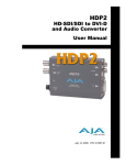
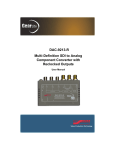
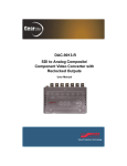
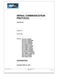
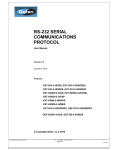
Using the HP DreamColor LP2480zx Monitor for Professional Video Applications Introduction While the original target market for the HP DreamColor LP2480zx Professional Display was colorcritical PC and workstation customers—especially those involved in computer graphics at the professional level—this product is also very well-suited to use in professional video post-production environments. The HP DreamColor LP2480zx can provide a level of performance very comparable to—and in some cases, exceeding—that of current “studio reference” monitors of any display technology, and at a very competitive price. Features of the HP DreamColor LP2480zx which make it an attractive choice for these applications include: The monitor is capable of accepting a video signals with a wide range of frame and field rates (including 29.97/59.94, 25/50, 24 and 23.9761) and displaying them without the use of a frame-rate conversion (FRC). This means that you can work at standard video rates and not see the tearing, frame skipping, judder, or other motion artifacts that are usually seen when video is displayed on an LCD monitor. A very broad “native” color gamut, plus built-in color gamut remapping capabilities which enable the monitor to accurately match all common color-space standards currently in use within the professional video community. Factory-calibrated “color space presets” are provided covering the ITU-R BT.709 and ITU-R BT.601 (SMPTE 145/SMPTE-C) standards, and a DCI-P3 Emulation preset provides 98% coverage for that color space. In addition, the monitor may be calibrated by the user (via the optional Advanced Profiling Solution calibration tool) to match other standard gamuts. The RGB LED backlight permits precise setting of the monitor “white point” (without affecting the video data being provided to the LCD panel), and gives the monitor a very wide range of white luminance adjustment; white may be set anywhere from a minimum of 50 cd/m2, for use in dark viewing environments, up to a 250 cd/m2 level suited to standard office lighting. The tone response (“gamma curve”) of the HP DreamColor LP2480zx may also be very accurately calibrated to duplicate the specified response of various output device standards, and/or match that of CRT-based reference monitors, while maintaining minimal neutral axis color drift. In other words, the grays stay gray. The LCD panel used in this monitor provides a very wide viewing angle with minimal off-axis color shift, and a static contrast ratio of 1000:1 (typ.). Coupled with the wide range of backlight and response curve adjustability, this permits the HP DreamColor LP2480zx to very closely duplicate the performance of traditional CRT-based studio reference monitors under a wide range of viewing conditions. In order to best utilize the HP DreamColor LP2480zx monitor in as a video display device, it is helpful to understand how the monitor receives, processes, and outputs a video signal. The following pages discuss these topics in detail and provide you with recommendations and configurations for the monitor. The LCD panel has the ability to sync at rates down to 47.952 Hz. These frame rates will be displayed at a doubled rate of 59.94, 50, 48, and 43.952 Hz respectively. This exact doubling will not introduce any frame-rate conversion artifacts. 1 Input The HP DreamColor LP2480zx offers a wide range of video inputs, including all popular PC/workstation interfaces and “consumer video” connections. The available inputs are: 2 – DVI-I (supporting both analog and digital signals) 1 – HDMI (version 1.3) 1 – DisplayPort (version 1.1) 1 – YPBPR component analog (using three “RCA” style jacks). 1 – composite analog (using an “RCA” style jack) 1 – S-video (using a standard DIN connector) Note: An analog VGA connection may also be used, via a VGA-to-DVI-I adapter cable (included with the monitor). For professional video applications, it is strongly recommended that one of the digital video inputs (HDMI, DVI, or DisplayPort) be used. All digital inputs support 8-bits per pixel inputs and the HDMI and DisplayPort additionally support 10-bits per color. Use of the S-video, composite, and component connections is not recommended, as these formats do not support RGB nor progressive signals and will therefore bypass the color-management features of the monitor. This is described in detail in the next section. While the HP DreamColor LP2480zx does not directly support the SDI/HD-SDI serial digital interface commonly used for interconnects in professional post and broadcast facilities, there are a number of products available which will cross-convert these signals into an HDMI, DisplayPort or DVI signal, permitting them to be fed into the LP2480zx. For the best performance we recommend using an HDMI or DisplayPort converter as those interfaces support the widest range of video frame rates and offer the highest bit-depth, resulting in smoother color gradients. HP recommends the following product for this purpose: Gefen, Inc. HD-SDI to HDMI Scaler Box (SKU: EXT-HDSDI-2-HDMIS) This device supports Dual-Link HD-SDI connectivity and can perform YCBCR to RGB color space conversions. Note that proper configuration of this box is required or an incorrect video image will result. We will discuss configuring the Gefen converter at the end of this white paper. Color Gamut Remapping As noted earlier, the HP DreamColor LP2480zx provides built-in color gamut remapping functionality, which permits it to accurately emulate a wide range of standard output devices and color spaces, including accurately matching specified RGB primaries, white point, gamma, and so on. This process involves the mathematical conversion of input video data so that it is accurately mapped into the monitor’s very wide “native” color gamut. However, due to the architecture of the “front end” electronics used in the HP DreamColor LP2480zx, the color gamut remapping circuitry will be bypassed if the following conditions exist: The monitor is fed a YCBCR (digital) or YPBPR (analog) signal. These signals must be color-space converted to RGB. The monitor is fed an interlaced or 1080-line progressive segmented frame (PsF) formatted signal (for example, 1080PsF/23.976). These signals must be converted to true progressive signals via a converter box. Using the HP DreamColor LP2480zx for professional video applications 2 The monitor is fed an analog signal via the composite, component or S-Video inputs. These signals must be converted to an RGB progressive signal and input via one of the digital inputs, such as HDMI. When a video source that meets one or more of the above criteria is sent directly to the LP2480zx, a warning will be displayed onscreen and the color space presets will be disabled in the On Screen Display (OSD) menu indicating that they cannot be selected. In this mode, the monitor is operating in its “native” mode, at the full panel gamut and with no tone response, gamma, or other corrections applied. The resulting image will typically be highly saturated and will not match the expected levels. Fortunately, Gefen converter interface mentioned above can compensate for all of the above conditions. Usage and Application Applying proper color gamut remapping allows the HP DreamColor LP2480zx to accurately emulate the display characteristics of a broadcast video monitor. Color space emulations are provided for both high definition (ITU-R BT.709) and standard definition (ITU-R BT.601) formats. These color spaces can be easily selected via the OSD’s “Color Space” menu. If you are working with high definition sources (either 1080-line or 720-line), you should choose the Rec.709 color space and the monitor will be configured to match the characteristics of a high definition broadcast monitor. Remember that any interlaced or PsF sources must be converted to true progressive source or color gamut mapping will be disabled. If you are working with standard definition sources (typically either NTSC or PAL), the color space you choose depends on how you convert the signal prior to feeding it to the monitor. The Gefen converter allows for three different methods of conversion for these signals. (We will discuss these options in greater detail at the end of this white paper.) – Choose the Rec.601 color space if you output the signal from the Gefen converter as either a 486/59.94 or 576/50 signal. – Choose the Rec.709 color space if you output the signal from the Gefen converter as any of the “Graphics” formats (ex. 640 x 480, 1024x768, and so on). – Choose the Rec.709 color space if you output the signal from the Gefen converter as any of the High Definition formats (ex. 1080p/59.94, 1080/50, 720p/59.94, 720p/50, and so on.) Video Black Level Depending on your video source, some additional adjustment of the HP DreamColor LP2480zx may be required. In the computer and print worlds, black and white are considered absolutes. “Black” is assigned a value of 0 (zero) for each channel and it is not possible for anything to be blacker than black. Likewise, “white” (assuming 8 bits per color) is assigned a value of 255 for each channel and it is not possible for anything to be whiter than white. (This corresponds to the print world where white typically means no ink has been applied to the page and black means that all of the ink has been applied.) Similarly, LCD monitors are designed to treat black and white as absolutes in order to attain the widest displayed contrast ratio possible. (CRTs do not treat black and white as absolutes as they are analog devices that can be calibrated to display a wide range of voltages and display those voltages at various levels of light output.) In the professional digital video world, however, black and white are not treated as absolutes. Instead, it is possible for a video signal to contain portions that are “blacker than black” and even that are “whiter than white.” The existence of these is due primarily to the desire to preserve aspects of the analog signal. “Blacker than black” voltages are used in analog signals for synchronization Using the HP DreamColor LP2480zx for professional video applications 3 and blanking2. Though these are not required for digital video, when ITU-R BT.601 – which codified the digital versions of the NTSC and PAL video formats – was created the standard was designed to allow for the capture of a portion of these signals. For example, blacker-than-black was preserved as many video engineers considered it critical to capture the rise time out of blanking and into the active picture3 when converting an analog signal to digital. These aren’t as important in a pure digital workflow, but preservation of these aspects of the analog was considered critically important. In the analog domain, whiter than white signals were allowed simply because a hard limit on voltage was not placed on the video standard. (Note that the value of “video white” was specified.) Though a limit was typically placed on signals broadcast over the air, analog video recording equipment allowed higher voltage whites to be captured up to the limits of the recording medium. This allowed videographers to “open up” the lens and capture very bright regions such as clouds and specular highlights on the surface of the water without losing picture information. The ITU-R BT.601 standard allows for the preservation of these up to a limit that is approximately 108% of peak white. In addition to the analog signal preservation requirements, the engineers designing the format realized that digital video processing, filtering, and compression could cause ringing and blooming artifacts which primarily manifest themselves in the highest and lowest bit values. By having a “blacker than black” and “whiter than white” region of the digital signal they could keep those signal artifacts outside of the voltages/bit values of black and white and reduce their negative impact on the picture. This was implemented in ITU-R BT.601 by assigning black (referred to as video black) a value of 16 digital (using 8 bits per pixel) and white (referred to as video white) a value of 235 digital (again using 8 bits per pixel). Because of this, when you display a video signal on a monitor, this higher value of black must be compensated for or your blacks will be lighter than they are supposed to be. (The fact that video white is a lower value than peak is considered less critical as it can be compensated for by adjusting the monitor brightness.) This “16–235” signal range is often referred to as the digital video mapping. And the “0–255” signal range is often referred to as the computer or graphics mapping. (In 10-bit digital video the range is 64–940 for digital video mapping and 0–1023 for computer/graphics mapping.) Usage and Application As the HP DreamColor LP2480zx is an LCD monitor, it uses 0–255 video signal mapping. Because of this, some adjustment must be made to the monitor’s Black Level or your blacks will be too bright and the image contrast will be reduced. In order to properly adjust the black level, you should display a test pattern on your video editing system that includes a “PLUGE” pattern. For example, the standard “SMPTE Bar” pattern includes a PLUGE pattern in the lower right hand region. There are also full-field (full screen) PLUGE patterns available on some test pattern generators. Note: the bar patterns provided by some software video editing systems do not include a PLUGE pattern, making it difficult to properly set the black level. In some cases third party hardware solutions for these systems provide a properly-formatted SMPUTE bar pattern that includes the PLUGE portion. The following illustration shows what a correctly-formatted SMPTE bar pattern should look like. If your system’s built-in pattern does not contain the gray vertical bars in the lower right region, you must capture bar from a signal generator and use that bar pattern. (Note: the brightness of the PLUGE pattern has been exaggerated so that it is easier to see in a printed document.) Though it is beyond the scope of this document to discuss the characteristics of an analog or digital video signal in detail, synchronization voltages (either –286mV or –300mV, depending on the video format) and blanking voltages (0mV) are used to both align the various lines of video in the analog signal and to turn off the electron gun drawing the image on a CRT monitor when the gun scanned from the end of one line back to the beginning of the next. 2 Rise time is defined as the portion of the signal where the voltage transitions from blacking to picture and is an important timing in analog signal transmission. Active picture is defined as the region of the image that contains video information; and he area outside of active picture is typically referred to either as the blanking region (for horizontal areas) or the sync region (for vertical areas). 3 Using the HP DreamColor LP2480zx for professional video applications 4 PLUGE pattern When the monitor’s black level is properly calibrated, the darkest bar (which is blacker than black) should no longer be visible; but the lightest bar (which is slightly brighter than video black) should still be visible. (The middle bar is video black.) As long as the bar on the right is still visible it is considered that the monitor is within the acceptable range for calibration. Note that it is very important that your HD-SDI converter be properly configured in order for you to be able to properly set the black level. We will discuss the configuration of the Gefen converter in the next section. To change the monitor’s black level: 1. Press any button on the bezel to activate the soft menu display. 2. If necessary, press the Input Control button and switch to the appropriate input (usually HDMI). 3. Using your video editing system or a test pattern generator, display the SMPTE bar (or full field PLUGE) pattern and confirm that it is being displayed on the HP DreamColor LP2480zx monitor. Make sure that the correct color space is selected, as described in the previous section. 4. After configuring your system or generator, press any button on the bezel again to reactivate the soft menu display. 5. Press the Open OSD button to display the OSD (on screen display). 6. Open the OSD and select the Image Control option. 7. From the Image Control menu, select the Black Level option. 8. Use the Increase Set and Reduce Set buttons to adjust the black level until the blackest of the three bars is no longer visible but the lightest of the three bars is still visible. The setting is relatively coarse. It is likely that an adjustment of just one or two values is all that will be required. 9. Once you are satisfied with the black level, press the Previous Menu button to return to the Image Control menu. 10. Select the Save and Return option to store the setting and return to the main menu. 11. Select the Exit option to leave the OSD. The black level adjustment is now stored as part of the active color space configuration. If you use other color spaces in your monitor—such as sRGB for a standard computer display—the black level for that space is not affected. Note that, unlike on a CRT display, the “brightness” or “luminance” control of an LCD does not affect the relationship between the video “black level” and the display’s effective “cutoff” point (the controls generally affect only the brightness of the LCD backlight), so adjusting the luminance control of the HP DreamColor LP2480zx will not affect the black level. Using the HP DreamColor LP2480zx for professional video applications 5 Configuring the Gefen Converter As noted earlier, the HP DreamColor LP2480zx is capable of very closely matching the appearance of standard studio reference monitors, including the CRT-based products which are still common in the industry. But in order to achieve this performance level the video signal must be fed through a signal converter so that what reaches the monitor is an RGB progressive signal. If your editing system or video equipment outputs an RGB true progressive signal via HDMI, you can connect it directly to the HP DreamColor LP2480zx and it the signal will be displayed correctly. Otherwise you will need to use a converter, such as the Gefen HD-SDI to HDMI converter, to attain the best result. Gefen produces both an HD-SDI to HDMI and an HD-SDI to DVI converter. We strongly recommend the HDMI converter as it will output a 10-bit signal to the HP DreamColor 2480zx monitor. (DVI connections do not support 10-bit signals and, as a result, the HD-SDI to DVI converter will always output an 8-bit signal.) The Gefen box will accept either a single-link or a dual-link HD-SDI or SDI signal. See the Gefen manual, if necessary, to assist you with the proper cabling of your HD-SDI source and the HDMI output. The Gefen HD-SDI to HDMI converter is configured via an on-screen display (OSD). You should set your HP DreamColor LP2480zx monitor to the HDMI input to display the Gefen signal. (It is not necessary to have an HD-SDI source connected to the Gefen box when you configure it, but it is recommended.) In order to properly configure you need to make adjustments to the Picture, Input, and Output options. You must use the supplied remote control to access the OSD. Press the MENU button on the remote to overlay the OSD over the video signal. Configuring the Picture Options There are three options within the Picture group that should be checked and adjusted, if necessary. Black Level — should be set to 0 (zero) Values greater than zero will result in the blacks being grayer than desired. Gamma — should be set to Default This option will instruct the Gefen converter to use either the Rec.709 or Rec.601 gamma, as required by the output signal. Color Range — should be set to 16–235 This will output the blacker-than-black and whiter-than-white portions to the monitor. Setting this to 0–255 will result in these values being clipped. Though this can increase the total available contrast, it is important—especially if you are doing color grading—that the whiter-than-white portions of the signal be displayed on the monitor. Otherwise you do not know whether any clipping of specular highlights and white texturing (such as those in clouds) was clipped in the source or by the Gefen. (As a rule it is never a good idea to grade a shot with any downstream clipping applied.) In addition to these three options, you may want to experiment with the Motion Threshold setting. This setting controls the de-interlacing circuitry. Though we’ve found that the default setting of 4 works well for most interlaced footage with the latest version of the Gefen firmware (as of the publication of this white paper), depending on the firmware installed in your Gefen box you may need to try a different value to eliminate any visible interlace tearing. Configuring the Input Options There are two options within the Input group that should be checked and adjusted, if necessary. Input Format — should be set to Auto Detect In rare instances it may be necessary to manually select the correct input format with certain HD-SDI equipment, but as a rule leaving it set to Auto Detect is the best choice. Using the HP DreamColor LP2480zx for professional video applications 6 Link Configuration — should be configured as required for your input source. If your source uses a single BNC connection you are using a Single Link connection. If you are unsure of the type of output provided by your video device, please consult its user manual for assistance. Configuring the “Set and Forget” Output Options Without question, this is the most important set of options and the ones that you will need to adjust whenever you switch video formats on your editing system or video device. We’ll cover the four options that you can “set and forget” first and then focus on the one you’ll need to return to when you switch formats. Available Formats — should be set to All If you set it to Monitor Supported you only be able to select a subset of the video formats supported by the HP DreamColor LP2480zx monitor. The monitor can lock to not just NTSC and PAL digital signals, but also all of the high definition systems in SMPTE 274M (for 1080-line formats) and SMPTE 296M (for 720-line formats). Remember, though, that only true progressive signals should be sent to the monitor. Link Configuration — should be set to RGB 4:4:4 The HP DreamColor LP2480zx monitor must receive an RGB-formatted signal in order to use its color gamut remapping capabilities. Using either of the other two options will result in the color gamut remapping circuitry being disabled. Frame Rate — should be set to Default The other options will override the chosen format’s frame rate and replace it with the selected rate. This option is designed for monitors that cannot lock to the correct frame rate. As the HP DreamColor LP2480zx can lock to these rates, these options are not necessary and will introduce frame rate conversion artifacts. Genlock Reference —should be set to Video Input unless you have a properly-configured trilevel sync generator connected to both your editing system/video device and the Gefen box Remember that if you are using a tri-level sync generator, it must be reconfigured to output the correct sync signal whenever you switch high definition formats. For more information, please see the tri-level sync generator’s manual. Configuring the Video Output Format Option Due to the HP DreamColor LP2480zx’s requirement that it be fed a true progressive signal, it is very important that you set the correct output format for each possible input format. We do not recommend setting this option to Default as it can result in interlaced signals being sent to the monitor. The following table lists the possible input formats and the output format you should choose from this menu. Use the table as a reference whenever you switch from one video format to another. Please note that this table uses the SMPTE 274M/296M naming convention for video formats. This convention lists the number of active lines, the frame type (progressive or interlaced) and the frame/field rate. (The line count and frame type are separated from the frame/field rate by a forward slash.) It is important to understand that this convention uses a frame/field rate instead of just the frame rate which means that the field rate is used for interlaced formats and the frame rate is used for progressive formats. For example, the format 1080i/59.94 means that the format has 1080 active lines (and a frame size of 1920 x 1080), is interlaced and has a field rate of 59.94 which translates into a frame rate of 29.97. Similarly, the format 1080p/29.97 means that the format has 1080 active lines, is progressive and has a frame rate of 29.97. Some video editing applications always report the frame rate instead of using the SMPTE convention. For this reason we have also included the frame rate in a separate column. Standard definition input formats are simply named “NTSC” and “PAL,” but we use the format names provided in the Gefen menu for the output formats. Using the HP DreamColor LP2480zx for professional video applications 7 Input Format Frame Rate Output Format Option Notes NTSC 29.97 480p/59.94 or 1080p/59.94 The LP2480zx assumes a 4x3 aspect ratio for standard definition signals. If you are using a 16:9 aspect ratio use the 1080p/59.94 output format. PAL 25 576p/50 or 1080p/50 The LP2480zx assumes a 4x3 aspect ratio for standard definition signals. If you are using a 16:9 aspect ratio use the 1080p/50 output format. 1080p/59.94 59.94 1080p/59.94 Input PsF signals will be converted to true progressive. 1080p/50 50 1080p/50 Input PsF signals will be converted to true progressive. 1080i/59.94 29.97 1080p/59.94 1080i/50 25 1080p/50 1080p/29.97 29.97 1080p/29.97 Input PsF signals will be converted to true progressive. 1080p/25 25 1080p/25 Input PsF signals will be converted to true progressive. 1080p/24 24 1080p/24 Input PsF signals will be converted to true progressive. 1080p/23.976 23.976 1080p/23.98 Input PsF signals will be converted to true progressive. 720p/59.94 59.94 720p/59.94 720p/50 50 720p/50 720p/29.97 29.97 720p/29.97 720p/25 25 720p/25 720p/24 24 720p/24 720p/23.976 23.976 720p/23.98 Additional Notes on NTSC and PAL Input Formats Due to a firmware limitation, current versions of the HP DreamColor LP2480zx do not properly interpret the “non-square raster” used in the ITU-R BT.601 format. This unfortunately means that 4x3 NTSC images will be slightly stretched horizontally and 4x3 PAL images will be noticeably squeezed horizontally. Though we hope to address this issue in a future firmware update, you may want to use a 4x3 graphic format instead of the video format listed above so that the aspect ratio is displayed correctly. This choice is not without a tradeoff, though. If you chose a graphic format you must use a 60 Hz rate which will introduce frame rate conversion artifacts into your signal. You should test realworld imagery to determine if these artifacts are acceptable to you. If you wish to use a graphic format choose the 1600x1200/60 option in the Graphic Output Format menu. Conclusion The HP DreamColor LP2480zx can serve as a very accurate display in traditional video reference monitor applications, but does have some differences vs. other products in this category (especially with respect to traditional CRT studio monitors) that must be addressed to ensure optimum performance in this use. Proper use of the available OSD controls, along with the HP DreamColor Advanced Profiling Solution calibration tool and available video converter hardware where needed, should simplify setup of the display for use in video production and related fields. Using the HP DreamColor LP2480zx for professional video applications 8 For more information http://www.hp.com/go/monitors HP monitors http://h30267.www3.hp.com/country/us/en/dreamcolor HP DreamColor Technologies © 2009 Hewlett-Packard Development Company, L.P. The information contained herein is subject to change without notice. The only warranties for HP products and services are set forth in the express warranty statements accompanying such products and services. Nothing herein should be construed as constituting an additional warranty. HP shall not be liable for technical or editorial errors or omissions contained herein. 572774-001 March 2009 Using the HP DreamColor LP2480zx for professional video applications 9