1
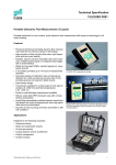
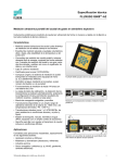
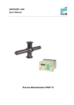
Technical Specification FLUXUS® G601 Portable Ultrasonic Flow Measurement of Gas Portable instrument for non-invasive, quick ultrasonic flow measurement with clamp-on technology for all types of piping Features • Non-invasive measurement using the clamp-on technology for precise bi-directional, highly dynamic flow measurement • Portable, easy-to-use flow transmitter with 2 flow channels, multiple inputs/outputs, an integrated data logger with a serial interface in the standard version • Automatic loading of calibration data and transducer detection reduce set-up times and provide precise, long-term stable results • Li-Ion battery provides up to 14 hours of measurement operation FLUXUS G601 supported by handle • Transducers available for a wide range of inner pipe diameters ( 7...1600 mm) and fluid temperatures ( -40...+200 °C ) • Proven clamp-on technology, transducers resistant to dust and humidity • Probe for wall thickness measurement available • Water and dust-tight; resistant against oil, many liquids and dirt • Robust, water-tight ( IP 67) transport case with comprehensive accessories • QuickFix for fast mounting of the flow transmitter in difficult conditions Measurement with transducers mounted by the portable Variofix VP Applications • Designed for industrial use in harsh environments, in gas processing and natural gas extraction, chemical industry and in the petroleum industry. Practical applications: - Measurement on natural gas pipelines and in natural gas storage installations - Measurement of synthesized gas and injection gas - Measurement for the gas supply industry - Supervision of permanently installed meters, service and maintenance Measurement equipment in transport case TSFLUXUS_G601V1-4EN_Leu, 2010-03-05 1 FLUXUS® G601 Technical Specification Table of Contents Function .......................................................................................................................................................... 3 Measurement Principle ..................................................................................................................................... 3 Calculation of Volumetric Flow Rate ................................................................................................................ 3 Number of Sound Paths.................................................................................................................................... 4 Typical Measurement Setup ............................................................................................................................ 5 Standard Volumetric Flow Rate ....................................................................................................................... 5 Flow Transmitter ............................................................................................................................................ 6 Technical Data ................................................................................................................................................. 6 Dimensions ...................................................................................................................................................... 8 Standard Scope of Supply ............................................................................................................................... 9 Connection of Adapters .................................................................................................................................. 10 Example for the Equipment of a Transport Case ........................................................................................... 11 Transducers .................................................................................................................................................. 12 Transducer Selection ..................................................................................................................................... 12 Transducer Order Codes ............................................................................................................................... 15 Technical Data ................................................................................................................................................ 16 Transducer Mounting Fixtures ................................................................................................................... 20 Coupling Materials for Transducers ........................................................................................................... 22 Damping Mats (optional) .............................................................................................................................. 23 Connection Systems .................................................................................................................................... 24 Transducer Cables ......................................................................................................................................... 24 Temperature Probes (optional) ................................................................................................................... 25 Wall Thickness Probe (optional) ................................................................................................................. 27 2 2010-03-05, TSFLUXUS_G601V1-4EN_Leu Technical Specification FLUXUS® G601 Function Measurement Principle In order to measure the flow of a medium in a pipe, ultrasonic signals are used, employing the transit time difference principle. Ultrasonic signals are emitted by a transducer installed on one side of a pipe, reflected by the opposite pipe wall and received by a second transducer. These signals are emitted alternately in the flow direction and against it. As the medium in which the signals propagate is flowing, the transit time of the ultrasonic signals in the flow direction is shorter than against the flow direction. The transit time difference, t, is measured and allows the flowmeter to determine the average flow velocity along the propagation path of the ultrasonic signals. A flow profile correction is then performed in order to obtain the area averaged flow velocity, which is proportional to the volumetric flow rate. The received ultrasonic signals will be checked for their usefulness for the measurement and the plausibility of the measured values will be evaluated. The complete measuring cycle is controlled by the integrated microprocessors. Disturbance signals will be eliminated. t Path of the ultrasonic signal 0 t 1 t 2 Transit time difference t Calculation of Volumetric Flow Rate Q = kRe . A . ka . t/(2 . tfl) where: Q kRe A ka t tfl - volumetric flow rate fluid mechanics calibration factor cross-sectional area of the pipe acoustical calibration factor transit time difference transit time in the medium TSFLUXUS_G601V1-4EN_Leu, 2010-03-05 3 FLUXUS® G601 Technical Specification Number of Sound Paths The number of sound paths is the number of transits of the ultrasonic signal through the medium in the pipe. Depending on the number of sound paths, the following methods of installation exist: • reflection mode The number of sound paths is even. Both of the transducers are mounted on the same side of the pipe. Correct positioning of the transducers is easier. • diagonal mode The number of sound paths is odd. Both of the transducers are mounted on opposite sides of the pipe. In the case of a high signal attenuation by the medium, pipe and coatings, diagonal mode with 1 sound path will be used. The preferred method of installation depends on the application. While increasing the number of sound paths increases the accuracy of the measurement, signal attenuation increases as well. The optimum number of sound paths for the parameters of the application will be detemined automatically by the transmitter. As the transducers can be mounted with the transducer mounting fixture in reflection mode or diagonal mode, the number of sound paths can be adjusted optimally for the application. . a a - transducer distance Reflection mode, number of sound paths: 2 a Diagonal mode, number of sound paths: 3 a>0 Diagonal mode , number of sound paths: 1 4 a<0 Diagonal mode , number of sound paths: 1, negative transducer distance 2010-03-05, TSFLUXUS_G601V1-4EN_Leu Technical Specification FLUXUS® G601 Typical Measurement Setup power supply/battery charging unit RS232 damping mat transducers U L T R A S O N IC F L O W M E T E R C H A N N E L A C H A N N E L B Q N E X T 7 4 Q - E N T E R M U X 1 0 O N 8 9 5 Q 6 2 O F F L IG H T 3 x O F F B R K D IS P B A T T E R Y Q + E N T E R D IS P 3 M O D E C O N transmitter analog/binary outputs e.g. external pressure sensor P T temperature probe analog inputs Example of a measurement setup in reflection mode with connection of the inputs to an external process pressure and process temperature measurement for standard volumetric flow rate calculation Standard Volumetric Flow Rate The standard volumetric flow rate can be selected as physical quantity to be measured. It will be calculated internally by: VN = V . p/pN . TN/T . 1/K where: VN V pN p TN T K - standard volumetric flow rate operational volumetric flow rate standard pressure (absolute value) operational pressure (absolute value) standard temperature in K operational temperature in K gas compressibility factor The operational pressure p and the operational temperature T of the medium will be entered directly as fixed values into the transmitter. Or: If inputs are installed (optional), pressure and temperature can be measured by the customer and fed in the transmitter. The gas compressibility factor K will be entered in the transmitter: • as fixed value or • as approximation according to e.g. AGA8 or GERG TSFLUXUS_G601V1-4EN_Leu, 2010-03-05 5 FLUXUS® G601 Technical Specification Flow Transmitter Technical Data FLUXUS design portable measurement measuring principle flow velocity transit time difference correlation principle 0.01...35 m/s, pipe diameter dependent repeatability 0.15 % of reading ±0.01 m/s accuracy - volumetric flow rate medium temperature compensation flow transmitter power supply battery power consumption number of flow measuring channels signal damping measuring cycle (1 channel) response time housing material degree of protection according to EN 60529 weight fixation operating temperature display menu language measuring functions physical quantities totalizers calculation functions diagnostic functions data logger loggable values capacity 6 G601 ± 1...3 % of reading ±0.01 m/s depending on application ± 0.5 % of reading ±0.01 m/s with field calibration gases with a ratio of the characteristic acoustic impedances of pipe wall and gas < 3000, e.g. nitrogen, air, oxygen, hydrogen, argon, helium, ethylene, propane corresponding to the recommendations in ANSI/ASME MFC-5M-1985 100...240 V/50...60 Hz (power supply), 10.5...15 V DC (socket at transmitter ) or integrated battery Li-Ion, 7.2 V/4.5 Ah operating time (without outputs, inputs and backlight): > 14 h <6W 2 0...100 s, adjustable 100...1000 Hz 1 s (1 channel), optional: 70 ms PA, TPE, AutoTex, stainless steel IP 65 1.9 kg QuickFix pipe mounting fixture -10...+60 °C 2 x 16 characters, dot matrix, backlit English, German, French, Dutch, Spanish operational volumetric flow rate, standard volumetric flow rate, mass flow, flow velocity volume, mass average, difference, sum sound velocity, signal amplitude, SNR, SCNR, standard deviation of amplitudes and transit times all physical quantities, totalized values and diagnostic values > 100 000 measured values 2010-03-05, TSFLUXUS_G601V1-4EN_Leu Technical Specification FLUXUS communication interface serial data kit software (all WindowsTM versions) cable adapter transport case dimensions outputs number accessories range accuracy active output passive output range open collector optorelay binary output as alarm output - functions binary output as pulse output - pulse value - pulse width inputs number accessories designation connection range resolution accuracy range accuracy passive input range accuracy internal resistance TSFLUXUS_G601V1-4EN_Leu, 2010-03-05 FLUXUS® G601 G601 RS232/USB - FluxData: download of measured data, graphical presentation, conversion to other formats (e.g. for ExcelTM) - FluxKoef: creating medium data sets RS232 RS232 - USB 500 x 400 x 190 mm The outputs are galvanically isolated from the transmitter. see standard scopes of supply on page 9, max. on request output adapter (if number of outputs > 4) current output 0/4...20 mA 0.1 % of reading ±15 A Rext < 200 Uext = 4...16 V, dependent on Rext Rext < 500 frequency output 0...5 kHz 24 V/4 mA binary output 26 V/100 mA limit, change of flow direction or error 0.01...1000 units 1...1000 ms The inputs are galvanically isolated from the transmitter. see standard scopes of supply on page 9, max. 4 input adapter (if number of inputs > 2) temperature input Pt100/Pt1000 4-wire -150...+560 °C 0.01 K ±0.01 % of reading ±0.03 K current input passive: -20...+20 mA 0.1 % of reading ±10 A Ri = 50 , Pi < 0.3 W voltage input 0...1 V 0.1 % of reading ±1 mV Ri = 1 M 7 FLUXUS® G601 Technical Specification Dimensions 59 FLUXUS G601 C H A N N E L B Q N E X T O N 8 7 Q - 4 E N T E R M U X 1 0 D IS P 9 5 Q 2 6 L IG H T E N T E R D IS P 3 O F F M O D E 3 x O F F B R K Q + 213 U L T R A S O N IC F L O W M E T E R C H A N N E L A B A T T E R Y C O N 226 in mm 8 2010-03-05, TSFLUXUS_G601V1-4EN_Leu Technical Specification FLUXUS® G601 Standard Scope of Supply application outputs passive current output binary output frequency output inputs temperature input passive current input voltage input accessories transport case power supply, power cable battery output adapter input adapter adapter for voltage or current inputs QuickFix pipe mounting fixture for transmitter serial data kit measuring tape damping mats with installation kit wall thickness probe user manual, Quick Start Guide connector board at the upper side of the transmitter G601 Standard all flow measurements on gas G601 Multifunctional sophisticated measuring tasks, e.g. temporary substitute of other flowmeters with use of actual physical quantities (e.g. pressure, temperature) for calculation of the standard volumetric flow rate and simultaneous measured value output 2 2 - 2 2 1 - 1 2 1 x x x - x x x x 2 3 x x x x x x x x x x x C H A C H - C O M M P 4 P 3 P 2 D C P 1 - IN B C H T 1 /T 3 P 3 ...P 8 A O u tp u t TSFLUXUS_G601V1-4EN_Leu, 2010-03-05 T 2 /T 4 C H C O M M P 2 B D C - IN P 1 + + O u tp u t In p u t 9 FLUXUS® G601 Technical Specification O u tp u t P 6 P 7 P 8 Connection of Adapters P 4 P 5 input adapter P 3 + output adapter adapter for voltage and current inputs transducers measuring channel A transducers measuring channel B C H P 3 ...P 8 A T 1 /T 3 T 2 /T 4 C H C O M M P 2 D C P 1 B - IN + O u tp u t outputs In p u t inputs power supply/battery charging unit RS232 10 2010-03-05, TSFLUXUS_G601V1-4EN_Leu Technical Specification FLUXUS® G601 Example for the Equipment of a Transport Case serial data kit user manual, Quick Start Guide measuring tape power supply, power cable transducer pipe mounting fixture wall thickness probe (optional) coupling compound QuickFix pipe mounting fixture temperature probes (optional) transducers TSFLUXUS_G601V1-4EN_Leu, 2010-03-05 transmitter 11 FLUXUS® G601 Technical Specification Transducers Transducer Selection Step 1a Select a Lamb wave transducer: transducer order code GLG 11 GLH 7 GLK GLM 4 2 15 9 5 GLP GLQ 23 1...3 0.5...1 5 10 15 20 25 pipe wall thickness [mm] Step 1b If the pipe wall thickness is not in the range of the Lamb wave transducers, select a shear wave transducer: transducer order code GSG 14 GSK 5 GSM GSP 2.5 1.5 23 9 5 3 5 10 15 20 25 pipe wall thickness [mm] recommended possible Step 2 inner pipe diameter d dependent on the flow velocity v of the medium in the pipe The transducers are selected from the characteristics (see next page). Lamb wave transducers are selected from the left column, shear wave transducers from the right column. Lamb wave transducers: If the values d and v are not in the range, diagonal mode with 1 sound path may be used, i.e. the same characteristics can be used with doubling the inner pipe diameter. If the values are still not in the range, shear waves transducers regarding the pipe wall thickness have to be selected in step 1b. 12 2010-03-05, TSFLUXUS_G601V1-4EN_Leu Technical Specification FLUXUS® G601 Lamb wave transducers1 shear wave transducers1 Dmm 1200 GLG Dmm 1200 1000 1000 800 800 600 600 400 400 200 200 0 GSG 5 10 15 20 25 30 35 vms Dmm 1200 0 5 10 15 20 25 30 35 vms GLH 1000 800 600 400 200 0 5 10 15 20 25 30 35 vms Dmm 1200 GLK Dmm 1200 1000 1000 800 800 600 600 400 400 200 200 0 5 10 15 20 25 30 35 vms 0 Dmm 10 15 20 25 30 35 vms 120 100 100 80 80 60 60 40 40 20 GSM 140 120 20 5 10 15 20 25 30 35 vms 0 Dmm 5 10 15 20 GDP 25 15 25 30 35 vms GSP Dmm GLP 140 140 120 120 100 100 80 80 60 60 40 40 20 0 5 Dmm GLM 140 0 GSK 20 5 10 15 20 25 30 35 vms 0 5 10 20 30 35 vms Dmm GLQ 140 120 100 80 60 40 20 0 1 5 10 15 20 25 30 35 vms inner pipe diameter and max. flow velocity for a typical application with natural gas, nitrogen, oxygen in reflection mode with 2 sound paths (Lamb wave transducers)/1 sound path (shear wave transducers) TSFLUXUS_G601V1-4EN_Leu, 2010-03-05 13 FLUXUS® G601 Technical Specification Step 3 min. medium pressure Lamb wave transducers transducer medium pressure1 [bar ] order code metal pipe plastic pipe min. min. extended min. GLG 15 10 1 shear wave transducers transducer medium pressure1 [ bar ] order code metal pipe plastic pipe min. min. extended min. GSG 30 20 1 GLH 15 10 1 GSK 30 20 1 GLK 15 (d > 120 mm) 10 (d < 120 mm) 10 (d > 60 mm) 5 (d < 60 mm) 10 (d > 35 mm) 5 (d < 35 mm) 10 (d > 15 mm) 5 (d < 15 mm) 10 (d > 120 mm) 1 5 (d < 120 mm) 1 GSM 30 20 1 GSP 30 20 1 GLM GLP GLQ 1 - 1 - 1 depending on application, typical absolute value for natural gas, nitrogen, compressed air d - inner pipe diameter Examples step 1 2 3 pipe wall thickness selected transducer inner pipe diameter max. flow velocity selected transducer mm min. medium pressure selected transducer bar mm m/s 12 GLG or GLH 800 15 GLG 12 GLG or GLH 600 15 GLG or GLH 17 GLG 17 GLG or GLH influence of noise is reduced with increased transducer frequency, thus recommended: GLH 12 GLG or GLH 800 30 values not in the range of the characteristics, but by using diagonal mode with 1 sound path, the inner pipe diameter in the characteristics is doubled: GLG 17 GLG 30 GS 300 15 GSK 35 GSK Step 4 for determination of characters 4...11 of the transducer order code (temperature, explosion protection, connection system, extension cable) see page 15 Step 5 for the technical data of the selected transducer see page 16 et seqq. 14 2010-03-05, TSFLUXUS_G601V1-4EN_Leu Technical Specification FLUXUS® G601 Transducer Order Codes 1, 2 3 4 5, 6 7, 8 9...11 no. of character - extension cable connection system explosion protection - temperature transducer frequency transducer description GL set of ultrasonic flow transducers for gas measurement, Lamb wave GS set of ultrasonic flow transducers for gas measurement, shear wave G 0.2 MHz H 0.3 MHz (Lamb wave only) K 0.5 MHz M 1 MHz P 2 MHz Q 4 MHz (Lamb wave only) N normal temperature range E extended temperature range (shear wave transducers with transducer frequency M, Q) NN not explosion proof NL with Lemo connector XXX cable length in m, for max. length of extension cable see page 24 000 Lamb wave transducer 0.5 MHz, normal temperature range, connection system NL with Lemo connector example GL K - N NN NL - TSFLUXUS_G601V1-4EN_Leu, 2010-03-05 - 15 FLUXUS® G601 Technical Specification Technical Data Shear Wave Transducers GDG1NZ7 GSG-NNNNL MHz 0.2 medium pressure1 min. extended min. bar bar mm mm mm mm inner pipe diameter d2 min. extended min. recommended max. recommended max. extended pipe wall thickness min. max. material housing GDM1NZ7 GSM-NNNNL 1 GDP1NZ7 GSP-NNNNL 2 metal pipe: 20 metal pipe: 30 plastic pipe: 1 metal pipe: 20 metal pipe: 30 plastic pipe: 1 metal pipe: 20 metal pipe: 30 plastic pipe: 1 metal pipe: 20 metal pipe: 30 plastic pipe: 1 250 380 810 1100 70 80 500 720 30 40 80 120 15 20 40 60 5 - 2.5 - 1.5 - PEEK with stainless steel cap 304 (1.4301) PEEK IP 67 PEEK with stainless steel cap 304 (1.4301) PEEK IP 67 stainless steel 304 (1.4301) PEEK IP 67 stainless steel 304 (1.4301) PEEK IP 67 1699 5 1699 5 1699 4 1699 4 mm 129.5 mm 51 mm 67 126.5 51 67.5 60 30 33.5 60 30 33.5 mm 14 mm - m h h h contact surface degree of protection according to EN 60529 transducer cable type length dimensions length l width b height h dimensional drawing GDK1NZ7 GSK-NNNNL 0.5 h technical type order code transducer frequency l -40 +130 x -40 +130 x -40 +130 x b b b b operating temperature min. °C max. °C temperature compensation l l l -40 +130 x 1 depending on application, typical absolute value for natural gas, nitrogen, compressed air 2 shear wave transducers: typical values for natural gas, nitrogen, oxygen, pipe diameters for other gases on request pipe diameter min. recommended/max. recommended/max. extended: in diagonal mode and for a flow velocity of 15 m/s 16 2010-03-05, TSFLUXUS_G601V1-4EN_Leu Technical Specification FLUXUS® G601 Shear Wave Transducers (extended temperature range) technical type order code transducer frequency GDM2EZ7 GSM-ENNNL MHz 1 GDP2EZ7 GSP-ENNNL 2 medium pressure1 min. extended min. bar bar metal pipe: 20 metal pipe: 30 plastic pipe: 1 metal pipe: 20 metal pipe: 30 plastic pipe: 1 mm mm mm mm 30 40 80 120 15 20 40 60 mm 2.5 mm - 1.5 PI with stainless steel cap 304 (1.4301) PI IP 65 6111 4 6111 4 mm 62.5 mm 32 mm 40.5 62.5 32 40.5 m h contact surface degree of protection according to EN 60529 transducer cable type length dimensions length l width b height h dimensional drawing PI with stainless steel cap 304 (1.4301) PI IP 65 h inner pipe diameter d2 min. extended min. recommended max. recommended max. extended pipe wall thickness min. max. material housing operating temperature min. °C max. °C temperature compensation -30 +200 x b l b l -30 +200 x 1 depending on application, typical absolute value for natural gas, nitrogen, compressed air 2 shear wave transducers: typical values for natural gas, nitrogen, oxygen, pipe diameters for other gases on request pipe diameter min. recommended/max. recommended/max. extended: in diagonal mode and for a flow velocity of 15 m/s TSFLUXUS_G601V1-4EN_Leu, 2010-03-05 17 FLUXUS® G601 Technical Specification Lamb Wave Transducers GRH1NC3 GLH-NNNNL 0.3 GRK1NC3 GLK-NNNNL 0.5 medium pressure1 min. extended bar metal pipe: 10 metal pipe: 10 min. bar metal pipe: 15 plastic pipe: 1 metal pipe: 15 plastic pipe: 1 metal pipe: 10 (d > 120 mm) 5 (d < 120 mm) metal pipe: 15 (d > 120 mm) 10 (d < 120 mm) plastic pipe: 1 mm mm mm mm 190 220 900 1600 120 140 600 1000 60 80 300 500 7 15 4 9 PPSU with stainless steel cap 304 (1.4301) PPSU IP 65 PPSU with stainless steel cap 304 (1.4301) PPSU IP 65 PPSU with stainless steel cap 304 (1.4301) PPSU IP 65 1699 5 1699 5 1699 5 mm 128.5 mm 51 mm 67.5 128.5 51 67.5 128.5 51 67.5 m h contact surface degree of protection according to EN 60529 transducer cable type length dimensions length l width b height h dimensional drawing mm 11 mm 23 operating temperature min. °C max. °C temperature compensation -40 +170 x l b l b l -40 +170 x b inner pipe diameter d2 min. extended min. recommended max. recommended max. extended pipe wall thickness min. max. material housing h GRG1NC3 GLG-NNNNL MHz 0.2 h technical type order code transducer frequency -40 +170 x 1 depending on application, typical absolute value for natural gas, nitrogen, compressed air 2 Lamb wave transducers: typical values for natural gas, nitrogen, oxygen, pipe diameters for other gases on request pipe diameter min. recommended/max. recommended: in reflection mode and for a flow velocity of 15 m/s pipe diameter max. extended: in diagonal mode and for a flow velocity of 25 m/s 18 2010-03-05, TSFLUXUS_G601V1-4EN_Leu Technical Specification FLUXUS® G601 Lamb Wave Transducers GRM1NC3 GLM-NNNNL MHz 1 GRP1NC3 GLP-NNNNL 2 GRQ1NC3 GLQ-NNNNL 4 medium pressure1 min. extended min. bar bar metal pipe: 10 (d > 60 mm) 5 (d < 60 mm) plastic pipe: 1 metal pipe: 10 (d > 35 mm) 5 (d < 35 mm) plastic pipe: 1 metal pipe: 10 (d > 15 mm) 5 (d < 15 mm) plastic pipe: 1 mm mm mm mm 30 40 90 150 15 20 50 70 7 10 22 35 1 3 0.5 1 PPSU with stainless steel cap 304 (1.4301) PPSU IP 65 PPSU with stainless steel cap 304 (1.4301) PPSU IP 65 PPSU with stainless steel cap 304 (1.4301) PPSU IP 65 1699 4 1699 4 1699 3 mm 74 mm 32 mm 40.5 74 32 40.5 42 22 25.5 operating temperature min. °C max. °C temperature compensation remark -40 +170 x l b l b l h m h contact surface degree of protection according to EN 60529 transducer cable type length dimensions length l width b height h dimensional drawing mm 2 mm 5 -40 +170 x b inner pipe diameter d2 min. extended min. recommended max. recommended max. extended pipe wall thickness min. max. material housing h technical type order code transducer frequency -40 +170 x on request 1 depending on application, typical absolute value for natural gas, nitrogen, compressed air 2 Lamb wave transducers: typical values for natural gas, nitrogen, oxygen, pipe diameters for other gases on request pipe diameter min. recommended/max. recommended: in reflection mode and for a flow velocity of 15 m/s pipe diameter max. extended: in diagonal mode and for a flow velocity of 25 m/s TSFLUXUS_G601V1-4EN_Leu, 2010-03-05 19 FLUXUS® G601 Technical Specification Transducer Mounting Fixtures Order Codes 6 7...9 no. of character - outer pipe diameter description fixation - 5 size 4 measuring mode 3 transducer transducer mounting fixture 1, 2 TB tension belts VP portable Variofix A all transducers D reflection mode or diagonal mode R reflection mode M medium C chains N without fixation 055 10...550 mm 150 50...1500 mm 210 50...2100 mm 055 portable Variofix and chains example VP A - 20 D M - C - 2010-03-05, TSFLUXUS_G601V1-4EN_Leu Technical Specification FLUXUS® G601 Portable Variofix VP and Chains material: stainless steel 304 (1.4301), 301 (1.4310), 303 (1.4305) dimensions: 414 x 84 x 50 mm chain length: 2 m Portable Variofix VP and Magnets (optional) material: stainless steel 304 (1.4301), 301 (1.4310), 303 (1.4305) dimensions: 414 x 84 x 45 mm Tension Belts TB material: steel, powder coated and textile belt length: 5/7 m temperature: max. 60 °C outer pipe diameter: max. 1500/2100 mm TSFLUXUS_G601V1-4EN_Leu, 2010-03-05 21 FLUXUS® G601 Technical Specification Coupling Materials for Transducers normal temperature range (4th character of transducer order code = N) extended temperature range (4th character of transducer order code = E) < 100 °C < 150 °C 100...170 °C 150...200 °C <2h coupling compound type N coupling compound type E coupling compound type E coupling compound type E or H < 24 h coupling compound type N coupling compound type E coupling compound type E coupling foil type VT < 3 months coupling compound type N coupling compound type E coupling foil type VT coupling foil type VT Technical Data type coupling compound type N coupling compound type E coupling compound type H coupling foil type VT order code 990739-1 temperature °C -30...+130 material mineral grease paste 990739-2 -30...+200 silicone paste 990739-3 -30...+250 fluoropolymer paste 990739-0 -10...+150, peak max. 200 fluoroelastomer 990739-6 990739-14 990739-15 990739-5 remark for transducers with transducer frequency G, H, K for shear wave transducers with transducer frequency M, P for IP 68 shear wave transducers and Lambwave transducers with transducer frequency M, P for shear wave transducers with transducer frequency Q for Lambwave transducers with transducer frequency Q coupling foil not to be used for transducer mounting fixture with magnets 22 2010-03-05, TSFLUXUS_G601V1-4EN_Leu Technical Specification FLUXUS® G601 Damping Mats (optional) Damping mats will be used for the gas measurement to reduce noise influences on the measurement. Transducer damping mats will be installed below the transducers. Pipe damping mats will be installed at reflection points, e.g. flange, weld. transducer damping mat pipe damping mat b D l D - outer pipe diameter reflection point diagonal mode reflection mode Selection of Damping Mats type description transducer damping mat D for temporary installation (multiple use), fixed with coupling compound pipe damping mat A for temporary installation (multiple use), fixed with coupling compound B self-adhesive outer pipe diameter dimensions lxbxh mm mm techni- temperature transducer cal type frequency (3rd character of transducer order code) G H K M P °C remark < 80 80 450 x 115 x 0.5 900 x 230 x 0.5 900 x 230 x 1.3 x x x - x x - x D20S3 - D20S2 - D50S2 -25...+60 < 300 300 x 100 x 0.5 x x x x x A20S4 -25...+60 for quantity see table below 300 l x 100 x 0.9 x x x x x B35R2 -35...+50 l - see table below Quantity for Pipe Damping Mat - Type A (depending on the outer pipe diameter) outer pipe diameter D mm 100 13 200 26 300 38 transducer frequency G, H K, M, P 7 13 19 Length of Pipe Damping Mat - Type B (length l depending on transducer frequency and outer pipe diameter) outer pipe diameter D transducer frequency G, H K, M, P mm m m 300 12 6 500 32 16 1000 126 63 TSFLUXUS_G601V1-4EN_Leu, 2010-03-05 23 FLUXUS® G601 Technical Specification Connection Systems Connection System NL transducer frequency (3rd character of transducer order code) G, H, K cable length m Q S x y l1 x y l1 x y l1 x y l 2 3 25 2 2 25 2 1 25 1 1 20 > 25...100 m on request FLUXUS 1 M, P l x y x, y - transducer cable length l - max. length of extension cable Transducer Cables Technical Data item number standard length max. length temperature sheath material outer diameter cable jacket material outer diameter thickness color shield 24 m transducer cable 1699 see table above m °C -55...+200 stainless steel 304 (1.4301) mm 8 PTFE mm 2.9 mm 0.3 brown x extension cable 2551 5 10 see table above -25...+80 TPE-O 8 black x 2010-03-05, TSFLUXUS_G601V1-4EN_Leu Technical Specification FLUXUS® G601 Temperature Probes (optional) Technical Data order code type 670415-1 Pt100 design measuring range °C accuracy T accuracy T A s kg ±(0.15 °C + 2 . 10-3 . T [°C]), class A ≤ 0.1 K (3K < T < 6 K), more corresponding to EN 1434-1 50 aluminum IP 66 0.25 mm mm mm 0.5 670415-2 Pt100 clamp-on - 0.32 0.64 clamp-on plastic protection plate, isolation foam 15 15 20 A 14 30 27 B extension cable l h B 670414-2 Pt100 matched according to DIN 1434-1 4-wire -50...+250 ±(0.15 °C + 2 . 10-3 . T [°C]), class A ≤ 0.1 K (3K < T < 6 K), more corresponding to EN 1434-1 8 PEEK, stainless steel 304 (1.4301), Cu IP 66 l response time housing degree of protection according to EN 60529 weight (without connector) fixation accessories dimensions length l width b height h dimensional drawing 670414-1 Pt100 matched according to DIN 1434-1 4-wire -30...+250 h Connection Temperature Probe red/blue TSFLUXUS_G601V1-4EN_Leu, 2010-03-05 red white/blue white 25 FLUXUS® G601 Technical Specification Connector pin 1 2 3, 4, 5 6 7 8 cable of temperature probe white/blue red/blue not connected red white not connected extension cable blue gray 2 4 red white 5 8 1 6 3 7 Cables cable of temperature probe type standard length max. length cable jacket 26 m m 4 x 0.25 3 PTFE mm2 black or white extension cable LIYCY 8 x 0.14 mm2 gray 5/10/25 200 PVC 2010-03-05, TSFLUXUS_G601V1-4EN_Leu Technical Specification FLUXUS® G601 Wall Thickness Probe (optional) The pipe wall thickness is an important pipe parameter which has to be determined exactly for a good measurement. However, the pipe wall thickness often is unknown. The wall thickness probe can be connected to the flow transmitter instead of the flow transducers and the wall thickness measurement mode is activated automatically. Acoustic coupling compound is applied to the wall thickness probe which then is placed firmly on the pipe. The wall thickness is displayed and can be stored directly in the flow transmitter. Wall thickness measurement Technical Data technical type measuring range1 resolution linearity operating temperature cable length 1 DWQ1xZ7 DWP1EZ7 reverse polarity protected 1...200 0.01 0.1 mm mm mm °C m -20...+60 1.5 -20...+200, peak max. 540 1.2 The measuring range depends on the attenuation of the ultrasonic signal in the pipe. For strongly attenuating plastics (e.g. PFA, PTFE, PP) the measuring range is smaller. DWQ1xZ7 DWP1EZ7 TSFLUXUS_G601V1-4EN_Leu, 2010-03-05 27 FLUXUS® G601 , Technical Specification FLEXIM GmbH internet: www.flexim.com Wolfener Str. 36 e-mail: [email protected] 12681 Berlin 28 Germany Subject to change without notification. Errors excepted. Tel.: +49 (30) 93 66 76 60 FLUXUS® is a registered trademark of FLEXIM GmbH. Fax: +49 (30) 93 66 76 80 2010-03-05, TSFLUXUS_G601V1-4EN_Leu