1
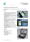
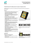
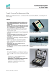
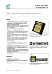
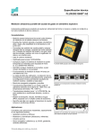
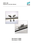
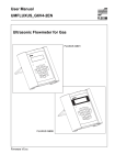
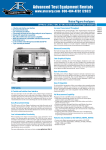
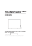
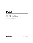
Technical Specification
FLUXUS® F601
Portable Ultrasonic Flow Measurement of Liquids
New portable instrument for non-invasive, quick ultrasonic flow measurement with clamp-on technology for
all types of piping
Features
• Non-invasive measurement using a clamp-on
method for precise bi-directional, highly dynamic flow
measurement
• New portable, easy-to-use flowmeter with 2 flow
measurement channels, multiple inputs/outputs,
an integrated data logger and a serial interface in the
standard version
• Automatic loading of calibration data and transducer
detection, reduces set-up times and provides
precise, long-term stable results
FLUXUS F601 supported by handle
• Li-Ion battery for 14 hours of measurement operation
• Proven clamp-on method; transducers are available
for a wide range of rated diameters from DN 6 to DN
6500 and temperatures from -40...+400 °C;
resistant to dust and humidity
• Integrated wall thickness measurement
• Water and dust-tight; resistant against oil, many
liquids and dirt
• Robust, water-tight (IP 67) transport case with
comprehensive accessories
• HybridTrek: automatic changeover between transit
time difference method and NoiseTrek for media with
a high proportion of solids or gases
• QuickFix for fast mounting of the flowmeter in difficult
conditions
Measurement with transducers mounted by fastening shoes
and flowmeter fixed to the pipe by the QuickFix pipe
mounting fixture
Applications
• Designed for industrial use, in particular for
application in
- chemical industry
- water and sewage systems
- cooling systems and air conditioners
- facility management
- aviation industry
Measurement equipment in transport case
TSFLUXUS_F601V1-1EN 9.7.2008
1
FLUXUS® F601
Technical Specification
Measuring Principle
HybridTrek
The volume flow of the medium is measured by means of the transit time difference principle. If the gaseous
or solid content of the medium increases occasionally during measurement, a measurement with this method
will be no longer possible. Instead NoiseTrek will be selected, a method achieving a stable measurement
even with a high gaseous or solid content.
The flowmeter switches automatically between transit time difference principle and NoiseTrek during measurement, the measurement setup does not need to be changed.
Transit Time Difference Principle
For the flow measurement of the medium, ultrasonic signals are used, employing the transit time difference
principle. Ultrasonic signals are emitted by a transducer installed on one side of a pipe, reflected on the opposite side and received by a second transducer. These signals are emitted alternatively in flow direction and
against it.
As the medium in which the signals propagate is flowing, the transit time of the ultrasonic signals in flow direction is shorter than against the flow direction.
The transit time difference Δt is measured and allows to determine the average flow velocity on the propagation path of the ultrasonic signals. A flow profile correction is then performed in order to obtain the area average of the flow velocity, which is proportional to the volume flow.
The received ultrasonic signals will be checked for their usefulness for the measurement and the plausibility
of the measured values will be evaluated. The complete measuring cycle is controlled by the integrated microprocessors. Disturbance signals will be eliminated.
t
Path of the ultrasonic signal
0
t
1
t
2
Transit time difference Δt
Calculation of the Flow Velocity
v = kα . Δt/(2 . tt)
with:
v
kα
Δt
tt
2
-
flow velocity
flowmeter constant
transit time difference
transit time of the medium
9.7.2008 TSFLUXUS_F601V1-1EN
FLUXUS® F601
Technical Specification
Number of Sound Paths
The number of sound paths is the number of transits of the ultrasonic signals through the medium in the pipe.
reflection mode: number of sound paths = even, the transducers are mounted on the same side of the pipe,
correct positioning of the transducers easier
diagonal mode: number of sound paths = odd, the transducers are mounted on opposite sides of the pipe
The mode to be used depends on the application. If the number of sound paths is increased, the accuracy of
the measurement will be better, but the signal attenuation is increased.
In case of a high signal attenuation by medium, pipe and coatings, diagonal mode with 1 sound path will be
used.
The optimum number of sound paths for the parameters of the application will be detemined automatically by
the flowmeter
As the transducers can be mounted with the supplied transducer mounting fixture in reflection mode or diagonal mode the number of sound paths can be adjusted optimally to the application.
.
a>0
Diagonal mode, 1 sound path
a<0
Diagonal mode, 1 sound path, negative transducer distance
a
Diagonal mode, 3 sound paths
a
a - transducer distance
Reflex mode, 2 sound paths
TSFLUXUS_F601V1-1EN 9.7.2008
3
FLUXUS® F601
Technical Specification
Flowmeter
Technical Data
FLUXUS
design
measurement
measuring principle
flow velocity
repeatability
accuracy1
with standard calibration
with extended calibration (option)
with field calibration2
medium
flowmeter
power supply
battery
power consumption
number of flow measuring channels
signal damping
measuring cycle (1 channel)
response time
material
degree of protection
according to EN 60529
weight
fixation
operating temperature
display
menu language
measuring functions
physical quantities
totalizers
calculation functions
data logger
loggable values
capacity
1
2
4
F601
portable
transit time difference correlation principle,
automatic NoiseTrek selection for measurements with high gaseous or solid content
0.01...25 m/s
0.15 % of reading ±0.01 m/s
±1.6 % of reading ±0.01 m/s
±1.2 % of reading ±0.01 m/s
±0.5 % of reading ±0.01 m/s
all acoustically conductive liquids with < 10 % gaseous or solid content in volume (transit time
difference principle)
100...230 V/50...60 Hz (power supply),
10.5...15 V DC (socket at flowmeter )
or battery
Li-Ion, 7.2 V/4.5 Ah
operating time (without outputs, inputs and backlight): > 14 h
<6W
2
0...100 s, adjustable
100...1000 Hz
1 s (1 channel), option: 70 ms
polyamid
IP 65
1.9 kg
QuickFix pipe mounting fixture
-10...+60 °C
2 x 16 characters, dot matrix, backlit
English, German, French, Dutch, Spanish
volume flow, mass flow, flow velocity, heat flow (if temperature inputs are installed)
volume, mass, option: heat quantity
average, difference, sum
all physical quantities and totalized values
> 100 000 measured values
for transit time difference principle, reference conditions and v > 0.15 m/s
reference uncertainty < 0.2 %
9.7.2008 TSFLUXUS_F601V1-1EN
FLUXUS® F601
Technical Specification
FLUXUS
communication
interface
serial data kit
software (all WindowsTM versions)
cable
adapter
outputs
number
accessories
range
accuracy
active output
passive output
range
open collector
optorelay
binary output as alarm output
- functions
binary output as pulse output
- pulse value
- pulse width
inputs
number
accessories
designation
connection
range
resolution
accuracy
range
accuracy
passive input
range
accuracy
internal resistance
TSFLUXUS_F601V1-1EN 9.7.2008
F601
RS232/USB
- FluxData: download of measured data, graphical presentation,
conversion to other formats (e.g. for ExcelTM)
- FluxKoeff: creating medium data sets
RS232
RS232 - USB
The outputs are galvanically isolated from the flowmeter.
see standard scopes of supply on page 6, max. on request
output adapter (if number of outputs > 4)
current output
0/4...20 mA
0.1 % of reading ±15 μA
Rext < 200 Ω
Uext = 4...16 V, dependent on Rext
Rext < 500 Ω
frequency output
0...10 kHz
24 V/4 mA
binary output
32 V/100 mA
limit, change of flow direction or error
0.01...1000 units
1...1000 ms
The inputs are galvanically isolated from the flowmeter.
see standard scopes of supply on page 6, max. 4
input adapter (if number of inputs > 2)
temperature input
Pt100/Pt1000
4-wire
-150...+560 °C
0.01 K
±0.01 % of reading ±0.03 K
current input
passive: -20...+20 mA
0.1 % of reading ±10 μA
Ri = 50 Ω, Pi < 0.3 W
voltage input
0...1 V
0.1 % of reading ±1 mV
Ri = 1 MΩ
5
FLUXUS® F601
Technical Specification
Dimensions (in mm)
59
FLUXUS F601
U L T R A S O N IC F L O W M E T E R
C H A N N E L A
O N
8
7
Q -
4
E N T E R
D IS P
9
5
M U X
Q
1
0
2
6
O F F
L IG H T
3 x O F F
B R K
213
C H A N N E L B
Q
N E X T
B A T T E R Y
Q +
E N T E R
D IS P
3
M O D E
C
O N
226
Standard Scopes of Supply
passive current output
binary output
temperature input
passive current input
application
accessories
F601 Standard
2
2
all flow measurements on liquids
-
connector board at the
upper side of the flowmeter
F601 Energy
2
2
2
including energy calculator for BTU
and heat measurements
transport case
- transport case
power supply, power cable
- power supply, power cable
battery
- battery
QuickFix pipe mounting fixture for - QuickFix pipe mounting fixture for
flowmeter
flowmeter
serial data kit
- serial data kit
fastening shoes and chains
- fastening shoes and chains
( transducer frequency M, Q)
( transducer frequency M, Q)
measuring tape
- measuring tape
user manual, Quick Start Guide
- user manual, Quick Start Guide
C H A
P 4
P 3
P 2
D C
P 1
- IN
B
C H
T 1 /T 3
A
T 2 /T 4
C H
C O M M
P 4
P 3
P 2
+
O u tp u t
6
C H
-
C O M M
D C
P 1
- IN
B
F601 Multifunctional
4
2
2
2
for sophisticated measuring tasks,
e.g. modeling of pump curves
- transport case
- power supply, power cable
- battery
- output adapter
- input adapter
- QuickFix pipe mounting fixture for
flowmeter
- serial data kit
- fastening shoes and chains
( transducer frequency M, Q)
- measuring tape
- user manual, Quick Start Guide
C H
T 1 /T 3
P 3 ...P 8
A
O u tp u t
T 2 /T 4
C H
C O M M
P 2
D C
P 1
B
- IN
+
+
In p u t
O u tp u t
In p u t
9.7.2008 TSFLUXUS_F601V1-1EN
FLUXUS® F601
Technical Specification
Example for the Equipment of a Transport Case
serial data kit
user manual and
Quick Start Guide
measuring tape
power supply, power cable
transducer pipe mounting fixture
coupling compound
wall thickness probe (option)
temperature probes (option)
transducers
TSFLUXUS_F601V1-1EN 9.7.2008
QuickFix pipe mounting fixture for
flowmeter
flowmeter
7
FLUXUS® F601
Technical Specification
Transducers
Shear Wave Transducers
technical type
CDG1NZ7
order code
transducer frequency
CDK1NZ7
FSG-NNNNL
CDM1NZ7
FSK-NNNNL
FSM-NNNNL
MHz 0.2
0.5
1
mm
mm
mm
mm
400
500
6500
6500
100
200
3600
4500
50
100
2500
3400
PEEK with stainless steel
cap
PEEK
IP 65
PEEK with stainless steel stainless steel
cap
PEEK
PEEK
IP 65
IP 65
option: IP 68
129.5
47
66.4
126.5
47
55.9
outer pipe diameter
contact surface
degree of protection
according to EN 60529
mm
mm
mm
60
30
33.5
h
dimensions
length l
width b
height h
dimensional drawing
h
min. extended
min. recommended
max. recommended
max. extended
material
housing
l
b
b
l
operating temperature
min.
°C
max.
°C
8
-40
+130
-40
+130
-40
+130
9.7.2008 TSFLUXUS_F601V1-1EN
FLUXUS® F601
Technical Specification
Shear Wave Transducers
technical type
order code
transducer frequency
CDQ1NZ7
FSQ-NNNNL
MHz 4
CDS1NZ7
FSS-NNNNL
8
mm
mm
mm
mm
10
25
400
400
6
10
70
70
stainless steel
PEEK
IP 65
stainless steel
PEI
IP 65
42.5
18
21.5
25
13
17
outer pipe diameter
mm
mm
mm
b
b
operating temperature
min.
°C
-40
-30
max.
+130
+130
TSFLUXUS_F601V1-1EN 9.7.2008
stainless steel
l
l
°C
stainless steel
h
h
min. extended
min. recommended
max. recommended
max. extended
material
housing
contact surface
degree of protection
according to EN 60529
dimensions
length l
width b
height h
dimensional drawing
9
FLUXUS® F601
Technical Specification
Shear Wave Transducers (High Temperature)
technical type
order code
transducer frequency
CDM1EZ7
FSM-ENNNL
MHz 1
CDQ1EZ7
FSQ-ENNNL
4
mm
mm
mm
mm
50
100
2500
3400
10
25
400
400
stainless steel
Sintimid
IP 65
stainless steel
Sintimid
IP 65
60
30
33.5
42.5
18
21.5
outer pipe diameter
mm
mm
mm
stainless steel
stainless steel
h
h
min. extended
min. recommended
max. recommended
max. extended
material
housing
contact surface
degree of protection
according to EN 60529
dimensions
length l
width b
height h
dimensional drawing
l
b
b
l
operating temperature
min.
°C
max.
°C
10
-30
+200
-30
+200
9.7.2008 TSFLUXUS_F601V1-1EN
FLUXUS® F601
Technical Specification
Order Code Key for Transducers
-
extension cable
connection
system
explosion
protection
-
temperature
frequency
transducer
model
description
FS
set of ultrasonic flow transducers for liquids measurement, shear wave
G
0.2 MHz
K
0.5 MHz
M
1 MHz (shear wave only)
Q
4 MHz (shear wave only)
S
8 MHz (shear wave only)
N
normal temperature range
E
extended temperature range (shear wave transducers with transducer frequency M, Q)
NN
not explosion proof
NL
with Lemo connector
XXX
cable length in m, for max. length of extension cable see page 14
030
shear wave transducer 1 MHz, normal temperature range, connection system
NL with 30 m extension cable and Lemo connector
example
FS
M
-
N
NN
-
TSFLUXUS_F601V1-1EN 9.7.2008
NL
-
11
FLUXUS® F601
Technical Specification
Transducer Pipe Mounting Fixtures
Fastening Shoes and Chains
for transducer frequency M, Q
for transducer frequency S
Fastening Shoes and Magnets (option)
12
9.7.2008 TSFLUXUS_F601V1-1EN
Technical Specification
FLUXUS® F601
Portable Variofix Mounting Fixture PVF and Chain
Portable Variofix Mounting Fixture PVF and Magnets (option)
TSFLUXUS_F601V1-1EN 9.7.2008
13
FLUXUS® F601
Technical Specification
Connection Systems
Connection System NL
transducer frequency
m
M, P
Q
S
y
l
x
y
l
x
y
l
x
y
l
2
3
≤ 100
2
2
≤ 100
2
1
≤ 50
1
1
≤ 20
FLUXUS
cable length
G, H, K
x
l
x
y
x, y - transducer cable length
l - max. length of extension cable
14
9.7.2008 TSFLUXUS_F601V1-1EN
FLUXUS® F601
Technical Specification
FLEXIM GmbH
internet: www.flexim.com
Wolfener Str. 36
e-mail: [email protected]
12681 Berlin
Germany
Subject to change without notification. Errors excepted.
Tel.: +49 (30) 93 66 76 60
FLUXUS® is a registered trademark of FLEXIM GmbH.
Fax: +49 (30) 93 66 76 80
9.7.2008 TSFLUXUS_F601V1-1EN