1
Océ User manual
Océ Web Buffer
Continuous Printing System
o
Océ Printing Systems GmbH
Copyright © 2004 - 2008Océ
All rights reserved. This documentation may not be reproduced, copied, changed or transmitted in any form, either in whole or in part, without written authorization from Océ.
Océ does not assume any responsibility or offer any guarantee regarding the information
contained in this document and excludes in particular any implied warranty claims regarding
the market capability or usability for a certain purpose. Océ also reserves the right to revise
this documentation from time to time and amend the content without announcing these
changes.
The designations Océ ColorStream®, Océ VarioStream®, Océ JetStream®, Océ VarioPrint®, Océ Web Buffer®, Océ PRISMA®production, Océ CustomTone®, and Océ
TonerSafeTM are protected by trademark.
All hardware and software names used are trademarks of their respective owners.
We also offer courses in our Training Center for Océ Web Buffer.
Information:
Phone +49 8121 72 3940
Fax +49 8121 72 3950
Océ Printing Systems GmbH
ITC
Postfach 1260
85581 Poing
Germany
Order number: A29246-X27-X-3-7680
Edition: 2008-06
Contents
Contents
Chapter 1
Documentation notes.................................................................................................5
Documentation notes - overview......................................................................6
Documentation signposts.................................................................................7
Symbols in the text............................................................................................9
Symbols in illustrations...................................................................................10
Manufacturer....................................................................................................11
Statutory requirements...................................................................................12
Chapter 2
Security......................................................................................................................13
Security - overview..........................................................................................14
Intended purpose ............................................................................................15
Operating and service clearance areas..........................................................16
Flagging of safety directives ..........................................................................17
Warning labels.................................................................................................18
Personnel indicators........................................................................................19
Operation..........................................................................................................20
Transport, repairs, fire.....................................................................................22
Safety regulations and standards...................................................................23
Residual dangers..............................................................................................24
Chapter 3
Description of the Océ Web Buffer.........................................................................25
Description of the Océ Web Buffer - overview..............................................26
Device overview...............................................................................................27
Vacuum unit......................................................................................................29
Paper web feed.................................................................................................31
Web buffer module..........................................................................................32
Operating elements.........................................................................................34
Operating elements - overview.................................................................34
Key control panel.......................................................................................35
Operator panel............................................................................................37
Operator panel - overview...................................................................37
Toolbar..................................................................................................39
Menu tree..............................................................................................41
Menu display........................................................................................42
Applying or resetting settings.............................................................43
Chapter 4
Océ Web BufferOperating the ................................................................................45
3
Contents
Operating the Océ Web Buffer - overview.....................................................46
Switching on modules.....................................................................................47
Setting up modules..........................................................................................48
Setting parameters..........................................................................................53
Removing the paper web................................................................................54
Switching off the vacuum unit and the web buffer module.........................56
Chapter 5
Océ Web BufferCleaning the ..................................................................................57
Cleaning the Océ Web Buffer - overview.......................................................58
Clean modules daily........................................................................................60
Cleaning modules weekly...............................................................................63
Chapter 6
Correcting problems.................................................................................................67
Correcting problems - overview.....................................................................68
Processing messages on the operator panel.................................................69
Correcting paper path problems.....................................................................72
Appendix A
Technical data...........................................................................................................73
Technical data..................................................................................................74
Appendix B
Your comments on this user guide.........................................................................77
Your comments on this user guide................................................................78
4
Chapter 1
Documentation notes
o
Documentation notes - overview
Documentation notes - overview
Introduction
The purpose of this documentation is to ensure that all work on the Océ Web Buffer is
carried out safely and correctly. It contains safety directives that must be strictly observed.
Each section is divided into small, easy-to-understand subject areas. Overviews at the
beginning of the sections help you to find the precise information you are looking for
quickly.
Note:
The Océ Web Bufferis required for operating the VarioStream 9000 (for color printing)
and ColorStream 10000 printing systems. For single-color printing only, the Océ Web
Bufferis not required.
Overview
Here you will find information on the following topics:
■ ‘Documentation signposts’ on page 7
■ ‘Symbols in the text’ on page 9
■ ‘Symbols in illustrations’ on page 10
■ ‘Manufacturer’ on page 11
■ ‘Statutory requirements’ on page 12
6
Chapter 1 - Documentation notes
Documentation signposts
Documentation signposts
Introduction
Documentation available to you on the Océ Web Buffer includes a printed user guide
and help on the operator panel. This help is updated with every new version of the operator panel software.
Security
This section provides all the necessary information on how to operate the Océ Web Buffer
safely and correctly.
Description of the Océ Web Buffer
This section describes the structure and function of the individual modules, as well as
the operating elements.
Operating the Océ Web Buffer
This section explains all work steps required for operating the Océ Web Buffer.
Cleaning the Océ Web Buffer
This section shows you the intervals for cleaning the different assemblies.
Correcting problems
This section helps you correct possible problems. The context-sensitive help in the operator panel of the printing system gives you detailed information on cause and correction
of specific error or warning messages.
Technical data
This section contains a summary of the most important technical data.
Index
The fastest way to find particular topics is via the detailed index at the end of the user
guide.
Chapter 1 - Documentation notes
7
Documentation signposts
Your comments on this user guide
We are interested in your opinion on this user guide for the Océ Web Buffer. You can
help us improve this user guide by answering the questions in this section.
8
Chapter 1 - Documentation notes
Symbols in the text
Symbols in the text
Display of operating elements on the operator panel
The operating element description is shown in inverted commas on the operator panel,
e.g.
'Configuration' menu.
Notes
Note:
This symbol indicates notes - tips for operating the Océ Web Buffer.
Safety directives
Symbols are used for the safety directives, as well as different alert words depending on
the degree of danger: see ‘Flagging of safety directives ’ on page 17.
Chapter 1 - Documentation notes
9
Symbols in illustrations
Symbols in illustrations
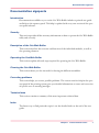
Introduction
If not otherwise indicated, diagrams and illustrations of actions depict the starting position
of the respective component for the described action.
To ease understanding, the illustrations only depict the components that are directly relevant to the immediate context.
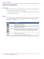
Arrows
Arrows denote the positions where you should perform an action or observe something
in particular. The colors of the arrows denote the type of actions and the sequence in
which they are performed:
#
Arrow
Meaning
Black arrow: Direction arrow
Perform this action first
Grey arrow: Direction arrow
Perform this action next
If further actions are depicted in an illustration, the numbers
on the arrows indicate the sequence of these further actions.
White arrow: Note arrow
An action should be performed in this area.
10
Chapter 1 - Documentation notes
Manufacturer
Manufacturer
Océ Web Buffer
The Océ Web Buffer was manufactured by:
Océ Printing Systems GmbH
Postfach 1260
85581 Poing
Germany
Chapter 1 - Documentation notes
11
Statutory requirements
Statutory requirements
Technical changes
The information, data and instructions in this documentation were up-to-date at the
time of going to press. The right of technical modifications due to further development
of the printing system is reserved. For this reason, the information, illustrations and descriptions in this documentation cannot give rise to any claims for modifications or additions to printing systems that have already been shipped and accepted.
Liability
No liability is accepted for damages resulting from:
■ Failure to comply with the documentation
■ Errors due to improper handling
■ Work performed incorrectly on the printing system
■ Use of non-original expendable parts, replacement parts and accessories
■ Use of non-original consumables
■ Unauthorized modification and retrofitting of the printing system by the agent or the
agent’s personnel.
12
Chapter 1 - Documentation notes
Chapter 2
Security
o
Security - overview
Security - overview
Caution:
Please also observe the safety directives in the documentation for the printing system and
any pre-processing and post-processing devices that may be connected.
Security
This section provides all the necessary information on how to operate the Océ Web Buffer
safely and correctly.
Overview
Here you will find information on the following topics:
■ ‘Intended purpose ’ on page 15
■ ‘Operating and service clearance areas’ on page 16
■ ‘Flagging of safety directives ’ on page 17
■ ‘Warning labels’ on page 18
■ ‘Personnel indicators’ on page 19
■ ‘Operation’ on page 20
■ ‘Transport, repairs, fire’ on page 22
■ ‘Safety regulations and standards’ on page 23
■ ‘Residual dangers’ on page 24
14
Chapter 2 - Security
Intended purpose
Intended purpose
Océ Web Buffer
The vacuum unit is exclusively intended for the storage of a continuous paper web, in
order to ensure a controlled paper web retraction by the printing system.
The web buffer module is exclusively intended for the storage of continuous paper webs
between the printing system and paper post-processing.
Any use for other purposes is regarded as improper. The manufacturer is not liable for
any damage resulting from improper use. The user alone bears the risk in this case. Only
strict observation of the notices and instructions in this documentation ensures use for
the intended purpose.
Chapter 2 - Security
15
Operating and service clearance areas
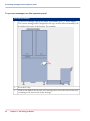
Operating and service clearance areas
Océ Web Buffer
The operating and service clearance areas must always be kept clear.
*: maximum paper web width
x: work area
16
Chapter 2 - Security
Flagging of safety directives
Flagging of safety directives
Definition
The following notational conventions are used for the safety directives in the text of the
manual:
#
Symbol
Alert word
Type or source of danger and consequences of failure to observe the
safety directives
Instructions on avoiding danger
Different alert words are used for the safety directives, depending on the degree of danger.
Two classes of safety directives
Caution:
Warns against dangers that could lead to injuries.
Attention:
Warns against situations that could lead to damage to the printing system or disruptions
to operation.
Example of a safety directive
Attention:
Fluid can get inside the printing system. This could cause irreparable damage to the
electrical and mechanical components.
Do not place cleaning fluids on top of or in the immediate vicinity of the printing system.
Take care to prevent fluids from seeping into the printing system.
Chapter 2 - Security
17
Warning labels
Warning labels
Flagging of danger points
Potential danger points on the web buffer module and vacuum unit are indicated using
the following label:
#
Label
Meaning
Warning: Live electric parts
There are live electric parts behind protective covers bearing
this sign. These protective covers may only be removed by authorized Océ Service personnel.
Warning: Rotating parts
Web traction unit infeed/web traction unit delivery
Parts of the body (particularly fingers), loosely hanging items
of clothing and jewelry (e.g. neckties, necklaces, belt ends) and
unprotected long hair can be crushed, trapped or pulled into
the printing system by the rotating mechanism in these areas.
18
Chapter 2 - Security
Personnel indicators
Personnel indicators
Agent
An agent is any individual or legal entity that uses the Océ Web Buffer or commissions
the use of the Océ Web Buffer.
Operator
The operator
■ is a person who has been directly instructed/trained to operate the Océ Web Buffer
and who has been informed about the tasks assigned to him. They are familiar with
the contents of the documentation.
■ is aware of the potential dangers of improper behavior .
■ has been informed about necessary safety installations, safety precautions and operating
conditions.
■ has been instructed or commissioned by the agent to operate the Océ Web Buffer .
Key operator
The key operator is an operator with a higher qualification assigned additional tasks by
the agent.
Service
Service employees are specialized Océ personnel who carry out all work on the Océ Web
Buffer that operators or key operators may not (e.g. any work on the electronics).
Chapter 2 - Security
19
Operation
Operation
Introduction
Observe the following instructions when operating the Océ Web Buffer:
Service personnel
Only operators, key operators and service personnel may use the Océ Web Buffer.
The printing system may not be operated by persons under the influence of alcohol or
drugs, or by persons taking certain types of medication, such as psychotropic drugs.
Before operating the printing system, carefully read through the documentation. If you
do not understand something in the documentation, please ask (e.g. contact Service).
In case of emergency, immediately power off the modules at the operating switch. In the
event of damage to the casing, power cable or operating elements, or penetration of fluids
or foreign bodies, call the appropriate Service representative.
Do not work with unprotected long hair or wear loosely hanging items of clothing (e.g.
ties, sleeves, scarves), and jewelry such as necklaces, bracelets and rings. These can cause
injury if caught in drive mechanisms.
Protective covers
Do not attempt to remove protective covers yourself; do not manipulate safety equipment
such as the switches monitoring the protective covers, fuses etc., and do not perform any
work not intended to be performed by operators.
Safe operation of the Océ Web Buffer is guaranteed only when the housing is fully
mounted. Only fully mounted housing ensures:
■ Protection from electrical shocks
■ Protection against injury from mechanical parts, e.g. cuts, drawing in, crushing
■ Protection against the spread of fire
■ Sufficient cooling of the printing system.
Keep all doors, covers, flaps and cover caps closed while the Océ Web Buffer is in operation. This ensures that limit values for electromagnetic compatibility are not exceeded.
Noise emission is also minimized in this manner.
Cleaning
Also observe the instructions in the section ‘Cleaning the - overview’ on page 58 for
cleaning the printing system.
20
Chapter 2 - Security
Operation
Always use an industrial vacuum cleaner with a grounded suction tube, rubber nozzle
and filter set for fine dust. An explosion-proof industrial vacuum cleaner must be used
for large toner quantities because there can be a high build-up of static charge when
draining toner spill.
Foreign bodies, noises
Make sure that no objects (e.g. jewelry chains, paper clips, coins etc.) or liquids get into
the interior of the printing system, since this may result in electric shocks or short circuits.
Do not place objects on the printing system, and especially do not place containers with
fluid, such as drinking bottles, glasses, cups or vases on top of or in the immediate vicinity of the printing system.
Should the Océ Web Buffer emit any unusual or noticeable noises or smells, power off
the system and contact Service.
Cooling, heat
Do not obstruct the cooling ducts. Failure to do so may result in overheating or combustion while the Océ Web Buffer is in operation.
Do not obstruct the operating and service clearance areas with other devices or objects
(see ‘Operating and service clearance areas’ on page 16).
Chapter 2 - Security
21
Transport, repairs, fire
Transport, repairs, fire
Transport
The Océ Web Buffer may only be moved or transported by Service or authorized transport
companies.
Repairs
Repairs to the Océ Web Buffer should only be carried out by Service. Access to locked
areas and areas that can only be opened with special tools is reserved for Service. Opening
the device without authorization and improperly effected repairs may put operators at
considerable risk.
Fire
Observe the following notes:
■ Poisonous gases can occur in any fire. They can also result from the Océ Web Buffer.
■ Self-contained breathing apparatus must be worn when fighting fire or smoke emission.
Notes to this effect should be deposited at the fire alarm center and with the local fire
department.
22
Chapter 2 - Security
Safety regulations and standards
Safety regulations and standards
Introduction
The Océ Web Buffer complies with the provisions of the following directives:
Machinery directive 98/37/EC
■
■
■
■
■
■
EN ISO 12100-1 2003 General design principles
EN ISO 12100-2 2003 General design principles
EN 294 1992 Safety clearances at danger points
EN 60204-1 1997 Electrical equipment of machinery
EN 1010-1 1997 Safety of paper processing machinery
EN27779 1991 Acoustics, noise measurements on machinery
EMC directive 89/336/EC
■
■
■
■
■
■
EN 61000-6 3 Generation of interference - domestic environment
EN 61000-6 4 Generation of interference - industrial area
EN 61000-6 1 Resistance to interference - domestic environment
EN 61000-6-2 1999 Resistance to interference - industrial area
FCC part 15 subpart B, Class A 1998 EMC standard (USA)
CSA C108.8 Class A EMC standard CAN
Low voltage directive 2006/95/EC
■
■
■
EN 60950-1 2001 Information technology equipment
UL 60950-1 2003 Information technology equipment USA
C22.2 No 60950-1 2003 Information technology equipment CAN
Environmental directive RoHS 2002/95/EC
■
2003 Prohibits the use of certain hazardous substances in electrical and electronic
equipment.
■
Chinese regulatory authority for environmental pollution due to electronic information
technology products
ACPEIP
Chapter 2 - Security
23
Residual dangers
Residual dangers
Introduction
Residual dangers are sources of danger that cannot be eliminated by design measures or
protective equipment.
Océ Web Buffer
The Océ Web Buffer is constructed in accordance with current standards of technology
and recognized rules concerning technical safety. Nevertheless, the following residual
dangers may affect the operator in the course of work:
■ Touching the edge of a moving paper web can cause cuts to the hands.
■ Static charges generated during paper processing can cause slight electrical shocks.
■ Paper processing generates paper dust.
24
Chapter 2 - Security
Chapter 3
Description of the Océ
Web Buffer
o
Description of the Océ Web Buffer - overview
Description of the Océ Web Buffer - overview
Description of the Océ Web Buffer
This section describes the structure and function of the individual modules, as well as
the operating elements.
Overview
Here you will find information on the following topics:
■ ‘Device overview’ on page 27
■ ‘Vacuum unit’ on page 29
■ ‘Paper web feed’ on page 31
■ ‘Web buffer module’ on page 32
■ ‘Operating elements - overview’ on page 34
26
Chapter 3 - Description of the Océ Web Buffer
Device overview
Device overview
Introduction
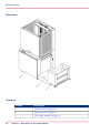
The vacuum unit is positioned behind the printing system, followed by an optional paper
web feed and then the web buffer module.
Chapter 3 - Description of the Océ Web Buffer
27
Device overview
Illustration
Overview
#
28
Module
Description
1
‘Vacuum unit’ on page 29
2
‘Paper web feed’ on page 31
3
‘Web buffer module’ on page 32
Chapter 3 - Description of the Océ Web Buffer
Vacuum unit
Vacuum unit
Introduction
The vacuum unit applies tension to the paper web between the printing system and the
Océ Web Buffer - thus providing lateral stabilization to the paper web.
The vacuum unit stores enough paper to ensure paper web retraction by the printing
system. In addition, in the event of high print speeds and light paper, the vacuum unit
prevents bunching and creasing of the loop between the printing system and the Océ
Web Buffer.
Illustration
Structure
Vacuum unit structure#
Assembly
Description
1
Feed plate
2
Pan
3
Eject rollers
4
Guide
5
Fans
Chapter 3 - Description of the Océ Web Buffer
29
Vacuum unit
30
Assembly
Description
5
Reflector
7
Photo cell loop monitoring
Chapter 3 - Description of the Océ Web Buffer
Paper web feed
Paper web feed
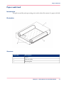
Introduction
The path around the print processing unit can be reduced by means of a paper web feed.
Illustration
Structure
#
Assembly
Description
1
Cover
2
Diverter roller
3
Bottom plate
Chapter 3 - Description of the Océ Web Buffer
31
Web buffer module
Web buffer module
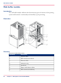
Introduction
The web buffer module calibrates the discontinuous paper web motion of the printing
system and forwards it continuously and smoothly to post-processing.
Illustration
Structure
Structure of web buffer module#
32
Assembly
Description
1
Pressure roller
2
Web traction unit infeed
3
Diverter roller
4
Antistatic strip
5
Latch bolt
6
Dancer with dancer rollers
7
Web traction unit delivery
Chapter 3 - Description of the Océ Web Buffer
Web buffer module
Assembly
Description
8
Circuit breaker cover with lock mechanism
The cover can only be opened if the module is switched on and
the dancer rollers are in the setup position.
Function
The web traction unit infeed draws the slightly damped paper web into the web buffer
module. The web traction unit delivery forwards the paper web to post-processing at an
average speed.
If the set parameters are exceeded (see ‘Setting parameters’ on page 53), the web buffer
module stops either the post-processing or the printing system.
Chapter 3 - Description of the Océ Web Buffer
33
Operating elements - overview
Operating elements
Operating elements - overview
Overview
#
Assembly
Description
1
Vacuum unit operating switch
2
Web buffer module key control panel (see ‘Key control panel’
on page 35)
3
Web buffer module operating switch
4
Operator panel (see ‘Operating elements - overview’ on page 34)
Note:
The Océ Web Buffer is started and stopped via the printing system.
34
Chapter 3 - Description of the Océ Web Buffer
Key control panel
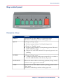
Key control panel
Description of keys
#
Key
Function
READY
Switches the Océ Web Buffer to operational status.
The dancer rollers keep tension on the paper web.
EJECT
In 'Setup' or 'Stop' status:
■ Initiates a paper advance by the printing system.
In 'Ready' or 'Standby' status:
■ Initiates a paper advance by the printing system if the web
buffer module is empty.
■ Empties the web buffer module if the printing system is not
printing.
INFEED
In 'Setup' or 'Stop' status:
■ Transports the paper web at an even speed of 10 m/min to
the web buffer module while the key is pressed.
INITIALIZE
Moves the dancer rollers to the setup position ('Setup' status).
Tension on the paper web is released.
STOP
Switches the Océ Web Buffer and the printing system to the
'Stop' status.
The dancer rollers keep tension on the paper web.
Chapter 3 - Description of the Océ Web Buffer
35
Key control panel
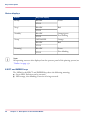
Status displays
#
Status
Key/LED display
'Ready'
READY
Green
STOP
'Stop'
READY
Red
STOP
'Standby'
'Setup'
READY
STOP
Orange/green
Fast blinking
INITIALIZE
Orange
READY
Red
STOP
'Running'
READY
STOP
Green
Slow blinking
Note:
All operating states are also displayed on the operator panel of the printing system (see
‘Toolbar’ on page 39).
EJECT and INFEED keys
The LEDs for the EJECT and INFEED keys have the following meaning:
■ Green LED: Function can be executed.
■ LED orange, slow blinking: Function is being executed.
36
Chapter 3 - Description of the Océ Web Buffer
Operator panel - overview
Operator panel
Operator panel - overview
Introduction
This section describes the individual areas of the operator panel including all menus,
symbols and buttons relevant for the Océ Web Buffer.
Overview
The operator panel is divided into the following areas:
#
Area
Description
1
‘Toolbar’ on page 39
2
‘Menu tree’ on page 41
3
‘Menu display’ on page 42
Chapter 3 - Description of the Océ Web Buffer
37
Operator panel - overview
Note:
If you change settings in a menu, ensure that you save these changes before switching
to another menu: see ‘Applying or resetting settings’ on page 43.
Note:
Detailed information on all menus and operating elements is available directly on the
operator panel via the context-sensitive direct help. Direct help can be called up by selecting the relevant menu or operating element and then pressing the F1 key.
Where necessary, all the requirements for setting the relevant parameters are also listed
in the direct help.
38
Chapter 3 - Description of the Océ Web Buffer
Toolbar
Toolbar
Introduction
You can use the toolbar to directly access and display the most important functions of
the Océ Web Buffer.
Overview
#
Area
Description
1
Toolbar for the Océ Web Buffer
2
Frame toolbar
Toolbar for the Océ Web Buffer
#
Button/display
Function
'Ready'
Switches the Océ Web Bufferto operational status.
The dancer rollers keep tension on the paper web.
'Stop'
Switches the Océ Web Bufferand the printing system to 'Stop'
status.
The dancer rollers keep tension on the paper web.
'Ready' / 'Setup' /
'Running' / 'Standby' /
'Stop' / 'Paused'
The current operational status is displayed in the center of the
toolbar.
The individual displays have different background colors depending on the operational status.
'Input speed
[m/min]'
'Output speed
[m/min]'
Displays the current speed of the infeed and output drive in
meters/minute.
'Buffer fill [inch]'
Displays the current buffer content of the Océ Web Bufferin
inches.
Service ticket
No function
Chapter 3 - Description of the Océ Web Buffer
39
Toolbar
Frame toolbar
The higher-level frame toolbar for the complete print processing unit is positioned in the
right-hand area. These buttons can be used to quickly access higher-level functions in the
print processing unit, and to switch directly to frequently used menus.
Note:
Detailed information on the frame toolbar is given in the printing system documentation.
40
Chapter 3 - Description of the Océ Web Buffer
Menu tree
Menu tree
Introduction
All the menus for the Océ Web Buffer can be accessed via the menu tree.
Note:
The menus displayed in the menu tree depend on the different rights for the individual
user categories.
This documentation describes all menu options normally set up for the user categories
"Operator" and "Key operator".
Overview
#
Menu
Description
'Web Buffer 9000'
The sub-menus contain all settings and displays relating to the
Océ Web Buffer.
'Operator configuration'
Setting for paper lengths, buffer range and speed, and acceleration of the web traction unit delivery.
'Service configuration'
Setting of the Océ Printing Systems GmbH by Service.
The Océ service documentation is available for Service.
'Counter display'
Displays various counters and versions, and graphic representations of speeds for web traction units (infeed and delivery) and
the buffer fill level.
'Error display'
Displays the current error message or warning.
Note:
Detailed information on the other main groups is provided in the VarioStream 9000
printing system documentation.
Chapter 3 - Description of the Océ Web Buffer
41
Menu display
Menu display
Introduction
This area shows the menu selected in the menu tree.
Direct help via the F1 key
Detailed information on all menus and operating controls is available directly in the operator panel via the context-sensitive direct help. The context-sensitive help system can
be called up by selecting the relevant menu or operating element and then pressing the
F1 key.
If necessary, all the requirements for setting the respective parameters are also listed in
the context-sensitive direct help. Specified standard settings and values are denoted in
bold.
42
Chapter 3 - Description of the Océ Web Buffer
Applying or resetting settings
Applying or resetting settings
'Apply' / 'Reset'
If you change parameters in a menu, you have to save these changes before switching to
another menu.
#
Button
Function
'Apply'
The current settings in the displayed menu are saved.
'Reset'
The current settings in the displayed menu are not saved, the settings
before the changes were made are restored.
Query
If you switch to another menu without applying the changed parameters, the 'Save current
changes?' query is displayed:
#
Button
Function
'Yes'
The parameters are saved.
The new menu is opened.
'No'
The parameters are not saved; the parameters in place before the
change are restored.
The new menu then opens.
'Cancel'
The parameters are not saved.
The menu remains open.
Chapter 3 - Description of the Océ Web Buffer
43
Applying or resetting settings
44
Chapter 3 - Description of the Océ Web Buffer
Chapter 4
Océ Web BufferOperating
the
o
Operating the Océ Web Buffer - overview
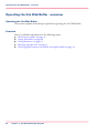
Operating the Océ Web Buffer - overview
Operating the Océ Web Buffer
This section explains all work steps required for operating the Océ Web Buffer.
Overview
Here you will find information on the following topics:
■ ‘Switching on modules’ on page 47
■ ‘Setting up modules’ on page 48
■ ‘Setting parameters’ on page 53
■ ‘Removing the paper web’ on page 54
■ ‘Switching off the vacuum unit and the web buffer module’ on page 56
46
Chapter 4 - Océ Web BufferOperating the
Switching on modules
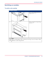
Switching on modules
To switch on the modules
#
Proceed as follows:
1.
Set the web buffer module operating switch to "I".
2.
Set the vacuum unit operating
switch to "I".
Note
The Océ Web Buffer will be switched to the'Setup' status, the dancer rollers
will move to the setup position.
Chapter 4 - Océ Web BufferOperating the
47
Setting up modules
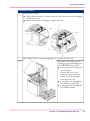
Setting up modules
Caution:
Rotating parts web traction unit infeed/web traction unit delivery areas
Parts of the body (particularly fingers), loosely hanging items of clothing and jewelry (e.g.
neckties, necklaces, belt ends) and unprotected long hair can be crushed, trapped or pulled
into the printing system by the rotating mechanism in these areas.
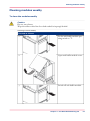
To set up the modules
Setting up modules#
Proceed as follows:
1.
Press the STOP key.
2.
Press the INITIALIZE key.
The dancer rollers move to the setup position.
3.
48
Chapter 4 - Océ Web BufferOperating the
Open cover.
The dancer rollers are blocked.
Setting up modules
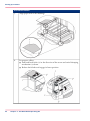
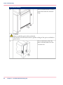
Proceed as follows:
4.
Lift pressure rollers:
■ Pull both latch bolts (1) in the direction of the arrow and swivel clamping
mechanism (2) up.
■ Release latch bolts and engage in upper position.
5.
Press EJECT button until enough paper is available for insertion.
6.
Manually insert paper web according to paper path diagram.
Use INFEED key as an aid:
■ Insert paper web in the vacuum unit pan.
Ensure that you do not
stretch the paper web too
much; the loop should be
near the photo cell.
■ Lead paper web through below the paper web feed.
■ Lead paper web through the
web buffer module.
Chapter 4 - Océ Web BufferOperating the
49
Setting up modules
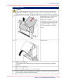
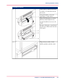
Proceed as follows:
50
7.
Align paper web to the markings.
8.
Set pressure rollers:
■ Pull both latch bolts (1) in the direction of the arrow and swivel clamping
mechanism (2) down.
■ Release latch bolts and engage in lower position.
Chapter 4 - Océ Web BufferOperating the
Setting up modules
Proceed as follows:
Caution
The fixed stop page for the paper web is to the left in paper path direction.
If the paper format is changed, the paper web in the vacuum unit must be
aligned to this stop page. The guide of this fixed stop page may not be adjusted.
9.
Align paper web to the left on
the fixed stop page (max.
2mm/0.08" clearance).
Pull guide to the upper right side
in the paper path direction and
position laterally to the paper
web (max 2 mm/0.08" clearance).
10.
Close cover.
11.
Press the STOP key.
The dancer rollers add tension to the paper web and the paper is pulled in
slightly.
12.
Press the READY key.
The web buffer module is now operational.
13.
Press EJECT until enough paper is available to set up the downstream device.
In so doing, check the paper web path.
Chapter 4 - Océ Web BufferOperating the
51
Setting up modules
Note:
The paper loop in the vacuum unit is automatically initialized for the printing system
web advance through the photo cell.
52
Chapter 4 - Océ Web BufferOperating the
Setting parameters
Setting parameters
To set the parameters for the Océ Web Buffer
#
Proceed as follows:
1.
On the operator panel, select the menu 'Web Buffer 9000' -> 'Operator configuration'.
2.
Set the following parameters:
■ 'Paper length':
'Infeed'
'Standby'
■ 'Buffer optimum range':
'Low'
'High'
■ 'Output speed':
'Fix'
'Variable' / 'Min' / 'Max'
'Acceleration'
Note
The permitted limit values are displayed on the operator panel.
Detailed information on these parameters elements is available directly on the
operator panel via the context-sensitive direct help. Direct help can be called up
by selecting the relevant operating element and then pressing the F1 key.
3.
Click the 'Apply' button.
Chapter 4 - Océ Web BufferOperating the
53
Removing the paper web
Removing the paper web
Caution:
To be able to remove the paper web, the Océ Web Buffer, the printing system and paper
post processing must be in the "Stop" status.
Note:
The paper web only needs to be removed when a paper web with a different format or
weight is to be used.
To remove the paper web
Removing the paper web#
Proceed as follows:
1.
Press the STOP key.
2.
Press the INITIALIZE key.
The dancer rollers move to the setup position.
3.
4.
54
Open web buffer module cover.
The dancer rollers are blocked.
Cut paper web in front of and behind the Océ Web Buffer.
Chapter 4 - Océ Web BufferOperating the
Removing the paper web
Proceed as follows:
5.
Lift pressure rollers:
■ Pull both latch bolts (1) in the direction of the arrow and swivel clamping
mechanism (2) up.
■ Release latch bolts and engage in upper position.
6.
Remove paper from the web buffer module, paper web feed and vacuum unit.
7.
Close web buffer module cover.
Chapter 4 - Océ Web BufferOperating the
55
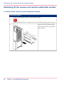
Switching off the vacuum unit and the web buffer module
Switching off the vacuum unit and the web buffer module
To switch off the vacuum unit and web buffer module
#
Proceed as follows:
1.
Click the following button on the operator panel:
and confirm the 'Do you really want to power off the printing system?' query.
2.
56
Chapter 4 - Océ Web BufferOperating the
Switch off web buffer module
and vacuum unit at the operating switches.
Chapter 5
Océ Web BufferCleaning
the
o
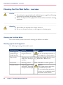
Cleaning the Océ Web Buffer - overview
Cleaning the Océ Web Buffer - overview
Caution:
■
■
If not otherwise expressly indicated, disable the power supply for all cleaning
operations by switching off operating switches.
Ensure that all protective equipment is fitted and functional after cleaning
operations.
Attention:
■
■
Please follow the manufacturer's safety directives.
Do not use chemical solvents or other aggressive cleaning agents.
Cleaning the Océ Web Buffer
This section shows you the intervals for cleaning the different assemblies.
Cleaning agents and equipment
The following cleaning aids should be used:
#
58
Cleaning agent
Purpose
Cleaning agent
(standard storebought quality)
Cleaning painted and
lacquered surfaces
Caution
Do not use chemical solvents or
other aggressive cleaning agents.
Paper towels
Cleaning areas soiled
with toner, developer
and dust
Standard store-bought, lint-free tissues
(e.g. KLEENEX, KALLE etc.)
Foam cloth
Cleaning surfaces
MOLTOPREN or similar qualities
Vacuum cleaner
Removing paper dust
and residue, toner and
developer residue/spill
Chapter 5 - Océ Web BufferCleaning the
Remarks
Caution
The vacuum cleaner must have
a grounded suction tube.
For vacuuming large quantities
of toner, use an explosion-proof
industrial vacuum cleaner.
Cleaning the Océ Web Buffer - overview
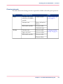
Cleaning intervals
The table shows the cleaning activities required for reliable and stable print operation:
#
Time
Cleaning location
Task
Daily
Vacuum unit, paper
web feed, web buffer
module
Inside/outside
Vacuum unit
Photo cell and reflector
Web buffer module
Pressure roller
‘Clean modules daily’ on page 60
Antistatic strip
Weekly
Vacuum unit
Diverter roller
Paper web feed
Diverter rollers
Web buffer module
Diverter roller
‘Cleaning modules
weekly’ on page 63
Dancer rollers
Chapter 5 - Océ Web BufferCleaning the
59
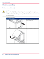
Clean modules daily
Clean modules daily
To clean the modules daily
Caution:
There can be a high build-up of static charge when vacuuming the toner spill.
Always use an industrial vacuum cleaner with a grounded suction tube, rubber nozzle
and filter set for fine dust. For larger toner quantities, the industrial vacuum cleaner must
be explosion-proof.
Cleaning modules daily#
Proceed as follows:
60
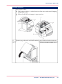
1.
Set the web buffer module operating switch to "I".
2.
Open web buffer module cover.
Chapter 5 - Océ Web BufferCleaning the
Clean modules daily
Proceed as follows:
3.
Switch off web buffer module.
4.
Use a vacuum cleaner to remove paper dust from the interior of the web buffer
module.
5.
Use a vacuum cleaner to remove
paper dust and toner residues
from all three pressure rollers.
6.
Close web buffer module cover.
7.
Use a vacuum cleaner to remove paper dust from the exterior of the paper web
module, paper web feed and vacuum unit.
Chapter 5 - Océ Web BufferCleaning the
61
Clean modules daily
Proceed as follows:
Use a vacuum cleaner to remove
paper dust from the antistatic
strip.
8.
Caution
Never touch the optics with your hands.
Oil and dirt on the hands results in quicker soiling of the optics and leads to
print errors.
9.
62
Chapter 5 - Océ Web BufferCleaning the
Use a soft cloth to clean the
photo cell and reflector in the
vacuum unit.
Cleaning modules weekly
Cleaning modules weekly
To clean the modules weekly
Caution:
Do not use solvents
Wipe the rollers with a lint-free cloth soaked in isopropyl alcohol.
Cleaning modules weekly#
Proceed as follows:
1.
Set the web buffer module operating switch to "I".
2.
Open web buffer module cover.
3.
Switch off web buffer module.
Chapter 5 - Océ Web BufferCleaning the
63
Cleaning modules weekly
Proceed as follows:
64
4.
Wipe dancer rollers with the
cloth.
5.
Close web buffer module cover.
Chapter 5 - Océ Web BufferCleaning the
Cleaning modules weekly
Proceed as follows:
6.
Open lock (4) and swivel diverter roller (1) in the direction of
the arrow.
Grasp feed plate (2) by the
openings (3) and remove.
Wipe the feed plate (2) with a
lint-free cloth soaked in isopropyl alcohol (do not use solvent).
Reinsert feed plate, swivel back
the diverter rollers and close the
lock again.
7.
Wipe diverter roller of web
buffer module with the cloth.
Chapter 5 - Océ Web BufferCleaning the
65
Cleaning modules weekly
Proceed as follows:
66
8.
Wipe diverter roller of vacuum
unit with the cloth.
9.
Wipe diverter roller of paper web
feed with the cloth.
Chapter 5 - Océ Web BufferCleaning the
Chapter 6
Correcting problems
o
Correcting problems - overview
Correcting problems - overview
Caution:
■
■
If not otherwise expressly indicated, disable the power supply for all maintenance tasks by switching off the operating switch.
Before powering on again and after maintenance tasks and repairs, ensure
that all protective equipment is fitted and functional.
Correcting problems
This section helps you correct possible problems. The context-sensitive help in the operator panel of the printing system gives you detailed information on cause and correction
of specific error or warning messages.
Stopping the Océ Web Buffer
There are two options:
■ No paper damaged. In this case, correct the problem such that production can continue
without removing paper from the system.
■ Paper damaged. In this case, the following procedure is recommended:
1. Remove an dispose of paper web.
2. Note down problem.
3. Reset the system.
Overview
Here you will find information on the following topics:
■ ‘Processing messages on the operator panel’ on page 69
■ ‘Correcting paper path problems’ on page 72
68
Chapter 6 - Correcting problems
Processing messages on the operator panel
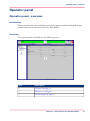
Processing messages on the operator panel
Introduction
Error messages and warnings for the Océ Web Bufferare recorded by the controller and
displayed on the printing system operator panel.
Note:
A Océ Web Buffer error message always triggers a stop for the printing system. Consequently, the web traction unit delivery on the web buffer module is immediately stopped.
The web traction unit infeed continues to run until the printing system itself actually
stops. The Océ Web Buffer then switches to the 'Stop' status, or to the 'Setup' status in
the event of a tear in the paper web.
Chapter 6 - Correcting problems
69
Processing messages on the operator panel
To process messages on the operator panel
#
Proceed as follows:
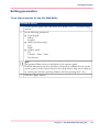
70
1.
To process a message, call up the menu 'Web Buffer 9000' -> 'Error display'.
The current message will be displayed at the top, and the affected assembly will
be displayed in color at the bottom. For example:
2.
Press the F1 key.
3.
Click on the link of the relevant error message and correct the cause of the error
according to the instruction in the message.
Chapter 6 - Correcting problems
Processing messages on the operator panel
Controlling the view of the Océ Web Buffer
Controlling the view of the Océ Web Buffer#
Button
Function
Switches back to the preset standard view after modifications.
Zooms in on the current view.
Zooms out of the current view.
Shifts the visible cutout in the direction of the arrow.
No function
Changes the view between:
■ Display of the message without graphic representation
■ Display of the message with graphic representation
■ Graphic representation only, without message display
Chapter 6 - Correcting problems
71
Correcting paper path problems
Correcting paper path problems
Vacuum unit
#
Problem
Cause
Correction
No loop in the vacuum
unit
The photo cells or reflectors are dirty.
The fans are not running.
Clean photo cells and reflectors (see ‘Clean modules
daily’ on page 60).
If the problem persists, inform Service.
Lateral paper web tears
The guide is set incorrectly.
Set up guide (see ‘Setting
up modules’ on page 48).
Problem
Cause
Correction
The web traction unit infeed runs very slowly after
the printing system starts.
The printing system is not
sending signals, or the
UP3i communication is
interrupted.
Restart the Océ Web
Buffer and the printing
system.
If the problem persists, inform Service.
Web traction unit delivery
is not working.
The downstream device
has not started.
Start downstream device.
Web buffer module
#
72
Chapter 6 - Correcting problems
Appendix A
Technical data
o
Technical data
Technical data
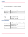
Technical data
This section contains a summary of the most important technical data.
Paper
#
Paper web width
Minimum: 165 mm (6.5")
Maximum: 520.7 mm (20.5")
Paper weight
28 g/m² to 240 g/m²
Buffer volume
Maximum 9 m (29.5 ft)
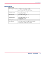
Mechanical conditions
#
Speed
max. 120 m/min (393.7 ft/min)
Weight
Web buffer module: 370 kg (816 lb)
Vacuum unit: 47 kg (104 lb)
Paper web feed: 30kg (60.2 lb)
Environmental conditions
#
74
Room temperature
Rated operation: 15° C to 30° C (59° F to 86° F)
Limit of operation: 10° C to 32° C (50° F to 89.6° F)
Relative humidity
Rated operation: 10 to 75%
Limit of operation: 10 to 80%
Lowest absolute humidity
Rated operation: 2 g/m³
Limit of operation: 1 g/m³
Highest absolute humidity
Rated operation: 22 g/m³
Limit of operation: 25 g/m³
Appendix A - Technical data
Technical data
Electrical values
Electrical values#
Electrical power supply
208 VAC ±10% 2LPE 50/60Hz
230 VAC ±10% LNPE 50/60Hz
Power supply 208V, two phases/earth
Nominal current
Web buffer module: 2.5 A
Vacuum unit: 0.4 A
Effective power
Web buffer module: 462 W
Vacuum unit: 87 W
Apparent power
Web buffer module: 600 VA
Vacuum unit: 96 VA
Back-up fuse
16 AT client-side
Heat emission
Web buffer module: 1577 BTU/h (1664 kJ/h)
Vacuum unit: 297 BTU/h (314 kJ/h)
Appendix A - Technical data
75
Technical data
76
Appendix A - Technical data
Appendix B
Your comments on this
user guide
o
Your comments on this user guide
Your comments on this user guide
Introduction
We are interested in your opinion on this user guide for the Océ Web Buffer. This will
help us improve this user guide. Please fill out these pages and fax them back to us: +49
8121 72 3420
Or send your comments by e-mail to: [email protected]
Thank you for your help.
Comments
Can you find the information you need quickly and easily?
O Yes
O No
Are your activities described fully and in sufficient detail?
O Yes
O No
Is the text easy to understand?
O Yes
O No
Are the illustrations easy to understand?
O Yes
O No — too abstract
O No — too detailed
Is the amount of background information sufficient for your needs?
O Yes
O No — not enough
O No — too much
What did you use to find the required information?
O Table of contents
O Index
Are you satisfied with this user guide?
O Yes
O No
78
Appendix B - Your comments on this user guide
Your comments on this user guide
What should we omit from, change or add to the user guide?
__________________________________________________________________
__________________________________________________________________
__________________________________________________________________
__________________________________________________________________
__________________________________________________________________
__________________________________________________________________
__________________________________________________________________
__________________________________________________________________
__________________________________________________________________
__________________________________________________________________
Sender
This reader's comment sheet is completed by:
Name:
Occupation:
Phone:
Company:
Address:
City:
Country:
Date:
(If you prefer to remain anonymous, please only fill in your occupation.)
Appendix B - Your comments on this user guide
79
Index
Index
E
Agent
Océ Web Buffer .............................................19
EJECT
Key .................................................................35
Errors
correcting .......................................................68
B
F
Buffer content
Display ...........................................................39
Button
Ready .............................................................39
Stop ................................................................39
Fire
........................................................................22
Foreign bodies
........................................................................21
Function
Web buffer module ........................................32
C
Cleaning
daily ...............................................................60
Safety directives ..............................................20
weekly ............................................................63
Cleaning agents and equipment
........................................................................58
Cleaning intervals
........................................................................59
Cooling
........................................................................21
D
Dancers
........................................................................32
moving together .............................................54
Delivery
Web traction unit ...........................................32
Device overview
........................................................................27
Display
Buffer content ................................................39
Infeed speed ....................................................39
Output speed ..................................................39
Documentation notes
..........................................................................6
Documentation signposts
..........................................................................7
80
G
Guide
setting up ........................................................48
I
INFEED
Key .................................................................35
Infeed
Web traction unit ...........................................32
Infeed speed
Display ...........................................................39
Initialization
........................................................................48
INITIALIZE
Key .................................................................35
Intended purpose
Vacuum unit ..................................................15
Web buffer module ........................................15
K
Key
EJECT ...........................................................35
INFEED ........................................................35
INITIALIZE ..................................................35
READY ..........................................................35
STOP .............................................................35
Key control panel
........................................................................35
Index
M
Manufacturer
........................................................................11
Menu display
........................................................................42
Menu tree
........................................................................41
Modules
cleaning ..........................................................58
N
Noises
........................................................................21
O
Operating and service clearance areas
Vacuum unit ..................................................16
Web buffer module ........................................16
Operating elements
........................................................................34
Operation
Safety directives ..............................................20
Operator
Océ Web Buffer .............................................19
Operator panel
........................................................................37
Output speed
Display ...........................................................39
P
Paper path problems
........................................................................72
Paper web
inserting .........................................................48
removing ........................................................54
Paper web feed
setting up ........................................................48
Structure .........................................................31
weekly cleaning ...............................................63
Parameters
Applying .........................................................43
Resetting .........................................................43
Pressure rollers
........................................................................32
Problems
correcting .......................................................68
Protective covers
........................................................................20
R
READY
Key .................................................................35
Ready
Button ............................................................39
Status display ..................................................36
Repairs
........................................................................22
Residual dangers
........................................................................24
Running
Status display ..................................................36
S
Safety directives
Flagging ..........................................................17
Operation .......................................................20
Safety regulations
........................................................................23
Security
........................................................................14
Setting parameters
........................................................................53
Setting up
paper web feed ................................................48
Status display ..................................................36
vacuum unit ...................................................48
web buffer module ..........................................48
Settings
Applying .........................................................43
Resetting .........................................................43
Standards
........................................................................23
Standby
Status display ..................................................36
Status display
Ready .............................................................36
Running .........................................................36
Setting up .......................................................36
Standby ..........................................................36
Stop ................................................................36
Statutory requirements
........................................................................12
STOP
81
Index
Key .................................................................35
Stop
Button ............................................................39
Status display ..................................................36
Structure
Paper web feed ................................................31
Vacuum unit ..................................................29
Web buffer module ........................................32
Switching off
vacuum unit ...................................................56
web buffer module ..........................................56
Switching on
vacuum unit ...................................................47
web buffer module ..........................................47
Symbol
in the text .........................................................9
Symbols
in illustrations .................................................10
T
Technical data
........................................................................74
Toolbar
........................................................................39
Transport
........................................................................22
V
Vacuum unit
Correcting paper path problems .....................72
daily cleaning ..................................................60
setting up ........................................................48
Structure .........................................................29
switching off ...................................................56
switching on ...................................................47
weekly cleaning ...............................................63
W
Warning labels
Vacuum unit ..................................................18
Web buffer module ........................................18
Web buffer module
Correcting paper path problems .....................72
daily cleaning ..................................................60
Function .........................................................32
Key control panel ...........................................35
setting up ........................................................48
82
Structure .........................................................32
switching off ...................................................56
switching on ...................................................47
weekly cleaning ...............................................63
Web traction unit
Delivery ..........................................................32
Infeed .............................................................32