1
User Manual of Color Camera
Version 2.1
Thank you for purchasing our product. If there is any question or request, please do not feel hesitated to
contact us.
This manual may contain several technically incorrect places or printing errors, and the content is subject
to change without notice. The updates will be added into the new version of this manual. We will readily
improve or update the products or procedures described in the manual.
1
Security Awareness
This manual contains several guidelines for all customers’ demand. Please read it carefully before
operating to ensure that you can use this product correctly and safely,and to avoid the danger or material
damage which may cause otherwise. Please preserve it well for future reference.
The precaution measure is divided into “Warnings” and “Cautions” as below:
Warnings: Serious injury or death may cause if any of the warnings is neglected.
Cautions: Injury or equipment damage may cause if any of the cautions is neglected.
Warnings Follow these safeguards to Cautions Follow these precautions to
prevent serious injury or death.
prevent potential injury or material
damage.
Warnings:
1.
Input voltage should meet both the SELV(Safety Extra Low Voltage) and the Limited Power Source
with AC 24V or DC 12V according to the IEC60950-1 standard. Please refer to technical
specifications for detail information.
2.
If the product does not work properly, please contact your dealer or the nearest service center. Never
attempt to disassemble the camera yourself. Users are responsible for any problem caused by
modifying or repairing without authorization.
3.
The operating environment shall be away from rain or moisture to lower the danger of fire or shock
hazard.
4.
The camera should be installed by qualified technicians, and comply with local laws and regulations.
5.
Precautions for short circuit are required for installing.
6.
Instructions for installation on walls: Please make sure that the camera can endure at least 50 Newton
(N)’s pulling downward.
2
Cautions:
1.
Make sure the power supply voltage is correct before using the camera.
2.
Do not drop the camera or subject it to physical shock.
3.
Do not touch CCD (Charge Coupled Device) modules with fingers. If cleaning is necessary, use clean
cloth with a bit of ethanol and wipe it gently. If the camera will not be used for an extended period,
please turn on the lens cap to protect the CCD from dirt.
4.
Do not aim the camera at the sun or extra bright places. A blooming or smear may occur otherwise
(which is not a malfunction however), and affecting the endurance of CCD at the same time.
5.
The CCD may be burned out by a laser beam, so when any laser equipment is on using, make sure
that the surface of CCD will not be exposed to the laser beam.
6.
Do not place the camera in extremely hot, cold(the operating temperature shall be-10℃~+60℃ ),
dusty or damp locations, and do not expose it to high electromagnetism radiation.
7.
To avoid heat accumulation, good ventilation is required for operating environment.
8.
Keep the camera away from liquid while on using.
9.
While on a delivery, the camera shall be packed in its original packing, or packing of the same
texture.
10. Regular part replacement: a few parts (e.g. electrolytic capacitor) of the equipment shall be replaced
regularly according to their average enduring time. The average time varies because of differences
between operating environment and using history, so regular checking is recommended for all the
users. Please contact with your dealer for more details.
3
Index
Chapter 1 Brief Introduction ............................................................................................................................................ 5
1.1
Introduction ....................................................................................................................................................... 5
1.2
Introduction to the Camera Appearance ............................................................................................................ 5
1.3
Side Elevation of the Camera ............................................................................................................................ 6
1.4
Introduction to the Rear Panel of the Camera ................................................................................................... 7
Chapter 2 Installation ............................................................................................................................................................ 9
2.1 Rear Panel .......................................................................................................................................................... 9
2.2 Power Supply ..................................................................................................................................................... 9
Chapter 3 Specification ....................................................................................................................................................... 10
Table 1......................................................................................................................................................................... 10
Table 2......................................................................................................................................................................... 11
Table 3......................................................................................................................................................................... 12
Table 4......................................................................................................................................................................... 13
Table 5......................................................................................................................................................................... 14
4
Chapter 1
Brief Introduction
1.1 Introduction
This color camera with advanced circuit designing incorporates a CCD module that offers high sensitivity.
It is ideal for surveillance and video processing systems, and provides excellent performances such as
high resolution, low distortion and low noise, etc.
The camera incorporates extraordinary features as below: Compact Structure Design
1/3 Inch SONY CCD
Day / Night with Auto Switch
Auto White Balance, Auto Gain Control, Electronic Shutter Control, and Backlight Compensation
Flickerless Mode
Digital Signal Processing
Auto Iris with DC / Video Driver
CS Mount Lens (Provide Optional Adapter for C Mount Lens)
Internal Synchronization
Advanced 3-axis mechanical design enables the camera to meet the installation requirement from
different environment by flexibly adjusting the lens into the require angle (Only DS-2CC511/591P-A
Support)
Advanced double board design enables heat dissipation and quality of the images
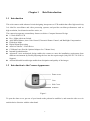
1.2 Introduction to the Camera Appearance
Dome cover
Core
Side Cover
Pedestal
Figure 1
To open the dome cover, put one of your hands on the pedestal to stabilize it, and rotate the side cover in
anticlockwise direction with the other hand.
5
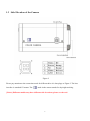
1.3 Side Elevation of the Camera
Figure 2
Please pay attention to the connection mode for different drive iris lens plugs as Figure 2. The lens
interface is standard CS mount. The
mark in the camera stands for day/night working.
[Notice] Different models may have different side elevations, please see the real.
6
1.4 Introduction to the Rear Panel of the Camera
Figure 3
①Level Adjusting:
Level adjusting is valid for iris adjusting in DC drive mode,while invalid for Video drive mode.
④Auto Iris Selecting:
Auto iris lens of both Video and DC drive modes can match this camera. Please select DD mode for
DC drive auto iris lens or VD mode for Video drive auto iris lens.
⑤SW Dial Switch Functions are listed as below.
NC
Invalid. Designed for extended use.
NAGC
Normal AGC: Normal automatic gain control. The gain is about 30dB when
turned on.
SAGC
Super AGC:Super automatic gain control. The gain is about 60dB when
turned on.
MIRROR
The image will be reversed horizontally with this function on.
7
FL
BLC
Use it to avoid the spot caused by different circuit power.
Back Light Compensation: Automatically adjust the exposure for back light
compensation.
AI
AES
Auto Iris:Turn the switch to AI for auto iris.
Auto Electronic Shutter:Turn the switch to AES for non-auto-iris mode.
ECLIPS
Restrain the partly brightness to make other parts clear.
SHARP
To get sharper edges for images, turn on the SHARP function.
SOFT
To get softer edges for the image, turn on the SOFT function.
[Notice] Different models may have different rear panels, please see the real.
8
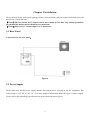
Chapter 2 Installation
Please check if all the items on the package list have been included with your camera and all the parts and
devices are of well function.
【Notice】The lens should be CS mount and its mass should be less than 1kg, and the prominent
part behind the mount surface should be less than 5mm.
【Notice】Please use a C mount adaptor for C mount lens.
2.1 Rear Panel
Connections for the rear panel:
Figure 4
2.2 Power Supply
Please make sure that the power supply matches the camera before you plug it into the equipment. The
usual charge is 12V DC or 24V AC. (For more detailed information about the types of power supply,
please refer to the technology specification for each referenced camera types.)
9
Chapter 3 Specification
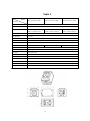
Table 1
Model
Parameter
DS-2CC102P(N)(-A)
DS-2CC112P(N)(-A)
Image Sensor
1/3 inch SONY Super HAD CCD
Signal System
PAL / NTSC
Effective Pixels
PAL: 500 (H)×582 (V)
PAL: 752 (H)×582 (V)
NTSC: 510 (H)×492 (V)
NTSC: 768 (H) ×494 (V)
DS-2CC192P(N)(-A)
Min. Illumination
0.5Lux @ F1.2
Electronic Shutter
1/50 (1/60)s-1/100,000s
Day & Night
Electronic
Auto Iris Lens
DC / Video
Lens Mount
C / CS mount
Horizontal Resolution
420 TVL
Synchronization
Internal synchronization
Video Output
1Vpp Composite Output
S/N Ratio
More than 48 dB
BLC
ON / OFF
Working Temperature
-10℃--60℃
Power Supply
12VDC, ±10%, “-A” series support12VDC / 24V AC, ±10%.
Power Consumption
2W MAX ("-A" series 3.5MAX)
Dimension (mm)
63×59×114
Weight
550g
480TVL
Notice: “-A” illustration of support AC24V±10% / DC12V±10% double power supply;
Dimension:
10
530TVL
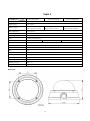
Table 2
Parameter
Model
DS-2CC502P (N)(-A)
DS-2CC512P (N)(-A)
DS-2CC592P (N)
Image Sensor
1/3 inch SONY Super HAD CCD
Signal System
PAL / NTSC
Effective Pixels
PAL: 500 (H) × 582 (V)
PAL: 752 (H) × 582 (V)
PAL: 752 (H) × 582 (V)
NTSC: 510 (H) ×492 (V)
NTSC: 768(H) ×494 (V)
NTSC: 768 (H) × 494 (V)
Min. Illumination
0.5Lux @ F1.2
Electronic Shutter
1/50 (1/60)s~1/100,000s
Day & Night
Electronic
Lens
3.6mm @ F2.0 (2.8mm, 6mm, 8mm, 12mm, 16mm option)
Horizontal Resolution
420 TVL
Synchronization
Internal Synchronization
Video Output
1Vp-p Composite Output (75Ω / BNC)
S/N Ratio
More than 48 dB
BLC
ON
Working Temperature
-10℃--60℃
Power Supply
12VDC, ±10% , (-A) Support 24VAC / 12VDC
Power Consumption
2W MAX
Dimension (mm)
Φ138x87
Weight
380g
480TVL
Notice: “-A” illustration of support AC24V±10%/DC12V±10% double power supply;
Dimension:
11
530TVL
Table 3
Model
Parameter
DS-2CC102P (N) -MM
DS-2CC112P (N) -MM
DS-2CC192P (N) -MM
Image Sensor
1/3 inch SONY Super HAD CCD
Signal System
PAL / NTSC
Effective Pixels
PAL: 500 (H)×582 (V)
PAL: 752 (H)×582 (V)
PAL: 752 (H)×582 (V)
NTSC: 510 (H)×492 (V)
NTSC: 768 (H) ×494 (V)
NTSC: 768 (H)×494 (V)
Min. Illumination
0.5Lux @ F1.2
Day & Night
Electronic
Electronic Shutter
1/50 (1/60)s-1/100,000s
Auto Iris Lens
DC / Video
Lens Mount
C / CS mount
Horizontal Resolution
420 TVL
Synchronization
Internal synchronization
Video Output
1Vpp Composite Output
S/N Ratio
More than 48 dB
BLC
ON / OFF
Working Temperature
-10℃~60℃
Power Supply
12VDC, ±10%
Power Consumption
1.5W MAX
Dimension (mm)
48×52×70
Weight
400g
480TVL
Dimension:
12
530TVL
Table 4
Parameter
Model
DS-2CC511P (N)-Ax
DS-2CC591P (N)-A
Image Sensor
1/3 inch SONY Super HAD CCD
Signal System
PAL / NTSC
Effective Pixels
PAL: 752 (H) × 582 (V)
Min. Illumination
0.5Lux @ F1.2
Day & Night
Electronic
Electronic Shutter
1/50(60)s~1/100,000s
Lens
3.5~9mm Auto Iris Lens (2.8-11mm auto iris lens option)
Horizontal Adjustment Range
0°~355°
Vertical Adjustment Range
0°- 90°
Horizontal Resolution
480 TVL
Synchronization
Internal Synchronization
Video Output
1Vp-p Composite Output (75Ω /BNC)
S/N Ratio
More than 48 dB
White Balance
Auto
BLC
ON / OFF
Working Temperature
-10℃~60℃
Power Supply
24VAC / 12VDC, ±10%
Power Consumption
3.5W MAX
Dimension (mm)
φ124×109.1
Weight
400g
NTSC: 768 (H) × 494 (V)
540TVL
Notice: “-A” illustration of support AC24V±10%/DC12V±10% double power supply;
Dimension:
13
Table 5
Parameter
Model
DS-2CC502P(N)-FB
DS-2CC512P(N)-FB
Image Sensor
1/3 inch SONY Super HAD CCD
Signal System
PAL / NTSC
Effective Pixels
DS-2CC592P(N)-FB
PAL: 500 (H) × 582 (V)
PAL: 752 (H) × 582 (V)
PAL: 752 (H) × 582 (V)
NTSC: 510 (H) × 492 (V)
NTSC: 768 (H) × 494 (V)
NTSC: 768 (H) × 494 (V)
Min. Illumination
0.5Lux @ F1.2
Electronic Shutter
1/50 (1/60)s---1/100,000s
Day & Night
Electronic
Lens
3.5-8mm (4--9mm option)
Horizontal Resolution
420TVL
Synchronization
Internal Synchronization
Video Output
1Vp-p Composite Output (75Ω / BNC)
S/N Ratio
More than 48dB
BLC
ON
Impact Protection
IEC60068-275 test, Eh, 50J; EN50102, exceeding IK10.
Working Temperature
-10℃~60℃
Power Supply
12VDC, ±10%
Power Consumption
2W MAX
Dimensions (mm)
φ140 ×92
Weight
660g
480TVL
Notice: “-FB” illustration of support Vandal proof;
Dimension:
14
540TVL