1
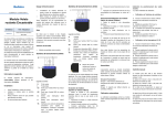
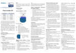
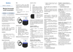
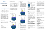
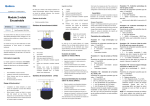
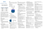
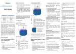
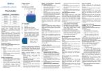
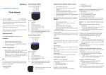
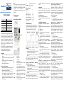
Qubino The INNOVATIVE and SMALLEST Smart meter Note! IR Output for IR external relay Do not connect the module to loads exceeding recommended values. Connect the module only in accordance to the below diagrams. Improper connections may be dangerous. It is recommended to use 65 A fuses for the line protection. 1imp/Wh Red - Pulse rate V Current I Power - Active W Package contents Power – Active total kWh Power - Reactive var Power – Reactive total kvarh Power – Apparent total kVAh Power Factor PF Electrical diagram 230VAC ORDERING CODE Z-WAVE FREQUENCY ZMNHTA1 868,4 MHz ZMNHTA2 921,4 MHz ZMNHTA3 908,4 MHz ZMNHTA4 869,0 MHz ZMNHTA5 916,0 MHz External relays It is possible to connect two external relay to Smart meter module. One controlled by built-in optical (IR) communication port on the side, second controlled by output on terminal 5. IR Module Inclusion (Adding to Z-wave network) Installation Before the installation disconnect power supply. Connect the module according to electrical diagram. Locate the antenna far from metal elements (as far as possible). Do not shorten the antenna. Notes for the diagram: LI Live input NI Neutral input Lo Live output No Neutral output 1 Input for IR external relay / Ext. relay 2 Neutral lead for input Danger of electrocution! 4 Live lead for External relay output 5 Output for External relay (max. 3W) S Service button (used to add or remove module from the Z-Wave network). Green - Power on (solid) / no ID (blinking slow 1s) / Inc./Exc. mode (blinking fast 0,5s) Yellow on – output on (any) / Yellow off – outputs off (both) Module installation requires a great degree of skill and may be performed only by a qualified and licensed electrician. Even when the module is turned off, voltage may be present on its terminals. Any works on configuration changes related to connection mode or load must be always performed by disconnected power supply (disable the fuse). Association enables Smart meter module to transfer commands inside Z-Wave network directly (without main controller) to other Z-Wave modules. Associated Groups: Group 1: Lifeline group (reserved for communication with the main controller), 1 node allowed. Configuration parameters This Z-Wave module is used intended for energy measurements in single-phase electrical power network and can be used in residential, industrial and utility applications. Meters measure energy directly in 2-wire networks according to the principle of fast sampling of voltage and current signals. A built-in microprocessor calculates energy, power and power factor from the measured signals. The module can be controlled through Z-wave network and it acts as repeater in order to improve range and stability of Z-wave network. It is designed to be mounted on DIN rail. Association Measurements Voltage Smart meter configuration parameters are not set to default values. LED1 LED2 Connect module to power supply auto-inclusion (works for about 5 seconds after connected to power supply) or press service button S for more than 2 second NOTE: For auto-inclusion procedure, first set main controller into inclusion mode and then connect module to power supply. Module Exclusion/Reset from Z-Wave network) (Removing Connect module to power supply bring module within maximum 1 meter (3 feet) of the main controller, enable add/remove mode on main controller press service button S for more than 6 seconds By this function all parameters of the module are set to default values and own ID is deleted. If service button S is pressed more than 2 and less than 6 second module is excluded, but Parameter no. 7 – Input 1 switch function selection Available configuration parameters (data type is 1 Byte DEC): default value 4 0 disabled 2 IR external relay control – mono stable push button 3 IR external relay control - bi stable switch 4 External relay control – mono stable push button 5 External relay control – bi stable switch Parameter no. 10 - Activate / deactivate functions ALL ON / ALL OFF Available configuration parameters (data type is 2 Byte DEC): default value 255 255 - ALL ON active, ALL OFF active. 0 - ALL ON is not active, ALL OFF is not active 1 - ALL ON is not active, ALL OFF active 2 - ALL ON active, ALL OFF is not active Smart meter module responds to commands ALL ON/ ALL OFF that may be sent by the main controller or by other controller belonging to the system Parameter no. 11 - Automatic turning off IR external relay output after set time When IR external relay is ON it goes automatically OFF after time defined by this parameter. Timer is reset to zero each time the module receive ON command regardless from where it comes (push button, associated module, controller,..). Available configuration parameters (data type is 2 Byte DEC): default value 0 0 - Auto OFF disabled 1 – 32535 = 1second – 32535 seconds. Auto OFF enabled with define time, step is 1s. Parameter no. 12 - Automatic turning on IR external relay output after set time When IR external relay is OFF it goes automatically ON after time defined by this parameter. Timer is reset to zero each time the module receive OFF command regardless from where it comes (push button, associated module, controller,..). Available configuration parameters (data type is 2 Byte DEC): default value 0 0 - Auto ON disabled 1 – 32535 = 1second – 32535 seconds. Auto ON enabled with define time, step is 1s. Parameter no. 13 - Automatic turning off External relay output after set time When External relay is ON it goes automatically OFF after time defined by this parameter. Timer is reset to zero each time the module receive ON command regardless from where it comes (push button, associated module, controller,..). Available configuration parameters (data type is 2 Byte DEC): default value 0 0 - Auto OFF disabled 1 – 32535 = 1second – 32535 seconds. Auto OFF enabled with define time, step is 1s. Parameter no. 14 - Automatic turning on External relay after output set time When External relay is OFF it goes automatically ON after time defined by this parameter. Timer is reset to zero each time the module receive OFF command regardless from where it comes (push button, associated module, controller,..). Available configuration parameters (data type is 2 Byte DEC): default value 0 0 - Auto ON disabled 1 – 32535 = 1second – 32535 seconds. Auto ON enabled with define time, step is 1s. Parameter no. 40 – Power reporting in Watts on power change Set value means percentage, set value from 0 – 100 = 0% - 100%. Available configuration parameters (data type is 1 Byte DEC): default value 10 0 – Reporting disabled 1 – 100 = 1% - 100% Reporting enabled. Power report is send (push) only when actual power in Watts in real time changes for more than set percentage comparing to previous actual power in Watts, step is 1%. NOTE: if power changed is less than 1W, the report is not send (pushed), independent of percentage set. When reporting Watts, module will automatically reports also V (Voltage), A (Amperes), Power factor, kVar (Reactive Power). Parameter no. 42 – Power reporting in Watts by time interval Set value means time interval (0 – 32535) in seconds, when power report is send. Available config. parameters (data type is 2 Byte DEC): default value 300 (power report in Watts is send each 300s) 0 – Reporting Disabled 1 – 32535 = 1 second – 32535 seconds. Reporting enabled, Power report is send with time interval set by entered value. When reporting Watts, module will automatically reports also V (Voltage), A (Amperes), Power factor, kVar (Reactive Power). Parameter no. 45 – Reset Power counters Available configuration parameters (data type is 1 Byte DEC): default value 0 0 no function 1 reset counter 1 – KWh 2 reset counter 2 – kVARh 4 reset counter 3 – kVAh 15 reset ALL counters Parameter no. 100 – Enable / Disable endpoints IR external relay and External relay Enabling IR external relay and External relay or both of them, means that endpoint (IR external relay) and endpoint (External relay) or both will be present on UI. Disabling them will result in hiding endpoints according to parameter set value. Note that hiding endpoint has no impact on its functionality. Available configuration parameters (data type is 1 Byte DEC): default value 0 0 - Endpoints IR external relay and External relay disabled 1 - Endpoints IR external relay disabled, External relay enabled 2 - Endpoints IR external relay enabled, External relay disabled 3 - Endpoints IR external relay and External relay enabled NOTE: After parameter change module has to be reconfigured! Parameter no. 130 – Serial Number Read only Parameter no. 131 – Meter Software reference Read only Parameter no. 132– Meter Hardware reference Read only Parameter no. 140– Voltage U1 Read only Parameter no. 141– Current I1 Read only Parameter no. 142– Active Power Total (Pt) Read only Parameter no. 143– Reactive Power Total (Qt) Read only Parameter no. 144– Power Factor Total (PFt) Read only Parameter no. 145– Energy Counter 1 – Active power accumulated Read only Parameter no. 146– Energy Counter 2 – Reactive power accumulated Read only Parameter no. 147– Energy Counter 3 – Apparent power accumulated Read only Technical Specifications Main terminals (LI, NI, Lo, No) 2 Contacts capacity: 1.5 ... 16 (25) mm Connection screws: M5 Max torque: 3.5 Nm (PZ2) Optional terminals (1,2,4,5) Contact capacity: 0.05 ... 1 (2.5) mm2 Screws: M3 Max torque: 0.6 Nm Measuring input: Type (connection): single phase (1b) Reference current (Iref): 5A Maximum current (Imax): 65 A Minimum current (Imin): 0.25 A Starting current: 20 mA Voltage (Un): 230 V (±20 %) Power consumption at Un: < 2W Nominal frequency (fn): 50 and 60 Hz Accuracy: Active energy and power: Standard EN 62053-21: class 1 Standard EN 50470-3: class B Reactive energy: Standard EN 62053-23: class 2 Optical communication: Type: IR - used to control BICOM432-40-IR Input (1): Rated voltage: 230 V (± 20%) Input resistance: 450 kOhm Safety: Indoor meter: yes Degree of pollution: 2 Protection class: II AC voltage test: 4 kV Installation Category: 300 Vrms cat. III Standard: EN 50470 Ambient conditions and EMC: According standards for indoor active energy meters. Temperature and climatic condition according to EN 62052-11 Ambient conditions and Safety: According standards for indoor active energy meters. Temperature and climatic condition according to EN 62052-11 Dust/water protection: IP20 Operating temp. range: -10 ... 40°C Storage temp. Range -40 ... 70°C Enclosure material: self extinguish complying UL94 V Indoor meter: yes Degree of pollution: 2 AC voltage test: 4 kV Standard: EN 50470 Wireless range up to 30 m indoors (depending on building materials) Weight 150g Colour RAL 7035 EC Directives conformity: EC Directive on Meas. Instruments 2004/22/EC EC Directive on EMC 2004/108/EC EC Directive on Low Voltage 2006/95/EC EC Directive WEEE 2002/96/EC COMMAND_CLASS_MULTI_CHANNEL_V4 Important disclaimer COMMAND_CLASS_MULTI_CHANNEL_ASSOCIATION_V3 Z-Wave wireless communication is inherently not always 100% reliable, and as such, this product should not be used in situations in which life and/or valuables are solely dependent on its function. COMMAND_CLASS_CONFIGURATION COMMAND_CLASS_VERSION_V2 COMMAND_CLASS_MANUFACTURER_SPECIFIC_V2 COMMAND_CLASS_DEVICE_RESET_LOCALLY COMMAND_CLASS_POWERLEVEL COMMAND_CLASS_ASSOCIATION_V2 Warning! COMMAND_CLASS_ASSOCIATION_GRP_INFO_V2 Do not dispose of electrical appliances as unsorted municipal waste, use separate collection facilities. Contact your local government for information regarding the collection systems available. If electrical appliances are disposed of in landfills or dumps, hazardous substances can leak into the groundwater and get into the food chain, damaging your health and well-being. When replacing old appliances with new once, the retailer is legally obligated to take back your old appliance for disposal at least for free of charge. COMMAND_CLASS_DEVICE_RESET_LOCALLY COMMAND_CLASS_MARK COMMAND_CLASS_BASIC COMMAND_CLASS_SWITCH_BINARY Endpoint 1 (IR external relay): Device Class: GENERIC_TYPE_SWITCH_BINARY SPECIFIC_TYPE_POWER_SWITCH_BINARY Command Classes: COMMAND_CLASS_ZWAVEPLUS_INFO_V2 COMMAND_CLASS_BASIC COMMAND_CLASS_SWITCH_BINARY_V2 COMMAND_CLASS_VERSION_V2 COMMAND_CLASS_ASSOCIATION_V2 This user manual is subject to change and improvement without notice. COMMAND_CLASS_ASSOCIATION_GRP_INFO_V2 COMMAND_CLASS_MULTI_CHANNEL_ASSOCIATION_V3 COMMAND_CLASS_MARK COMMAND_CLASS_BASIC NOTE: User manual is valid for module with SW version S1 (SW version is part of P/N)! Example: P/N: ZMNHTAx H1S1P1 Endpoint 2 (External relay): Device Class: GENERIC_TYPE_SWITCH_BINARY SPECIFIC_TYPE_POWER_SWITCH_BINARY Command Classes: COMMAND_CLASS_ZWAVEPLUS_INFO_V2 Dimensional drawings: COMMAND_CLASS_BASIC COMMAND_CLASS_SWITCH_BINARY_V2 COMMAND_CLASS_VERSION_V2 COMMAND_CLASS_ASSOCIATION_V2 COMMAND_CLASS_ASSOCIATION_GRP_INFO_V2 COMMAND_CLASS_MULTI_CHANNEL_ASSOCIATION_V3 COMMAND_CLASS_MARK COMMAND_CLASS_BASIC Z-Wave Device Class: ZWAVEPLUS_INFO_REPORT_ROLE_TYPE_SLAVE_ALWAYS_ON GENERIC_TYPE_METER NOTE: - Endpoints are shown/hidden by Parameter No. 100 - BASIC SET/GET on root device is mapped to basic set/get of both endpoints. SPECIFIC_TYPE_WHOLE_HOME_METER_SIMPLE Z-Wave Supported Command Classes: COMMAND_CLASS_ZWAVEPLUS_INFO_V2 COMMAND_CLASS_BASIC COMMAND_CLASS_SWITCH_ALL COMMAND_CLASS_SWITCH_BINARY_V2 COMMAND_CLASS_METER_V4 This product can be included and operated in any Z-Wave network with other Z-Wave certified devices from any other manufacturers. All constantly powered nodes in the same network will act as repeaters regardless of the vendor in order to increase reliability of the network. Qubino Goap d.o.o. Nova Gorica Ulica Klementa Juga 007 5250 Solkan Slovenia E-mail: [email protected] Tel: +386 5 335 95 00 Web: www.qubino.com Date: 24.9.2015 Document: Qubino_Smart meter user manual_V1.0_eng