1
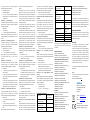
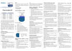
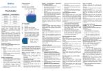
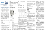
Qubino Package contents NOTE: When connecting temperature sensor to module 1) that has already been included, you first have to exclude according to module inclusion instructions. time-par.72) connected to I1 (up), initiates full slates turn module. Connect the sensor and re-include the module. 2) and up movement, until the push-button is released. Flush shutter Electrical diagram 230VAC Module Exclusion/Reset from Z-Wave network) The INNOVATIVE and SMALLEST Flush shutter ORDERING CODE Z-WAVE FREQUENCY ZMNHCD1 868,4 MHz ZMNHCD2 921,4 MHz ZMNHCD3 869,0 MHz ZMNHCD5 916,0 MHz Notes for the diagram: This Z-Wave module is used to control the motor of blinds, N Neutral lead rollers, shades, garage doors, gates, venetian blinds, etc L Live lead … The module can be controlled either through a Z-Wave Q1 Output for motor UP (open) network or through the wall switch. Q2 Output for motor DOWN (close) Precise positioning is supported for motors equipped with I2 Input for switch/push button DOWN (close) mechanical or electronic end switches. The module is I1 Input for switch/push button UP (open) designed to be mounted inside a “flush mounting box”, TS Terminal for digital temperature sensor (only hidden behind a traditional wall switch. Module measures for Flush shutter module compatible digital power consumption of motor and support connection of temperature sensor, which must be ordered digital temperature sensor. It is designed to act as separately). repeater in order to improve range and stability of Z-wave S network. Service button (used to Supported switches add or remove module Module supports mono-stable switches (push button) from and bi-stable switches. network). the Z-Wave Installation Before the installation disconnect power supply. Durability of the device depends on applied load. For Connect the module according to electrical diagram. resistive Locate the antenna far from metal elements (as far consumption of each individual electrical device, the as possible). durability exceeds 70.000 switches of each individual Do not shorten the antenna. electrical device. load (light bulbs, etc.) and may be performed only by a qualified and Module Inclusion (Adding to Z-wave network) licensed electrician. Module installation requires a great degree of skill sensor connected - if purchased), Even when the module is turned off, voltage may be present on its terminals. Any works on configuration Connect module to power supply (with temperature bring module within maximum 1 meter (3 feet) of the main controller, changes related to connection mode or load must be always performed by disconnected power supply enable add/remove mode on main controller, (disable the fuse). auto-inclusion (30 minutes after connected to power Note! supply) or Do not connect the module to loads exceeding press service button S for more than 2 second or recommended values. Connect the module only in press push button I1 three times within 3s (3 times accordance to the below diagrams. Improper connections may be dangerous. change switch state within 3 seconds) Quick press the switch/push-button connected to I1 input and wait until the shutter reach upper limit switch. Keeping pressed push-button (for time > full turn slates 3) time-par.72) connected to I2 (down), initiates shutter Quick press the switch/push-button connected to I2 input and wait until the shutter reach lower limit switch. down movement, until the push-button is released. Slates on end position - 180 degree Connect module to power supply 4) bring module within maximum 1 meter (3 feet) of the input and wait until the shutter reach upper limit switch. Clicking main controller, Slates tilting position calibration time-par.72) connected to I1 (up), initiates shutter up enable add/remove mode on main controller, (par. 71 set to 1) movement. press service button S for more than 6 second or When enabling venetian blind mode, position calibration Clicking press push button I1 five times within 3s (5 times for slats titling must be done. After that, blind position and time-par.72) connected to I2 (down), initiates slates change switch state within 3 seconds) in the first 60 angle of slates can be set. By default full turn for slates is turning towards start - 0 degree position, until the seconds after the module is connected to the power set to 1,5s. This value can be changed according to push-button is released. supply. slates types and time by value in parameter 72. If the shutter is moving, each click, of any push-button, By this function all parameters of the module are set to 1) Include and make module calibration according to will stop the movement. default values and own ID is deleted. section ‘Shutter positioning calibration’ Keeping pressed push-button (for time > full turn slates If service button S is pressed more than 2 and less than 6 2) Set parameter 71 to 1 ‘Venetian blinds’ time-par.72) connected to I1 (up), initiates shutter up second module is excluded, but configuration parameters 3) Reconfigure node using gateway movement, until the push-button is released. are not set to default values. 4) After module reconfiguration, beside main shutter Keeping pressed push-button (for time > full turn slates widget, another widget for slates control will appear on UI time-par.72) connected to I2 (down), initiates full slates Association 5) By default full turn movement is set to 1,5s. If this time turn and down movement, until the push-button is Association enables Flush shutter module to transfer is too long (after slates full cycle shutter starts moving up released. commands inside Z-wave network directly (without main or down), decrease this time defined with parameter 72. Quick press the switch/push-button connected to I1 push-button push-button (for (for time time < full < full turn turn slates slates Configuration parameters controller) to other Z-Wave modules. Associated Groups: Manual operation for shutter Parameter no. 10 - Activate/deactivate functions ALL Group 1: default reporting group (reserved for the main (par. 71 set to 0) ON / ALL OFF controller) Module allows connecting of push-buttons (mono-stable) Available config. parameters (data type is 2 Byte DEC): Group 2: basic on/off (triggered at change of the input I1 or switches (bi-stable) to I1 and I2 terminals. default value 255 state and reflecting its state) up to 16 nodes Clicking push-button (<2s) connected to I1 (up), initiates 255 - ALL ON active, ALL OFF active. Group 3: basic on/off (triggered at change of the input I2 up movement. 0 - ALL ON is not active ALL OFF is not active state and reflecting its state) up to 16 nodes Clicking push-button (<2s) connected to I2 (down), 1 - ALL ON is not active ALL OFF active Group 4: multilevel (triggered at changes of value of the initiates down movement. 2 - ALL ON is not active ALL OFF is not active Flush shutter position) up to 16 nodes. If the shutter is moving, each click, of any push-button, Flush shutter responds to commands ALL ON / ALL OFF Group 5: multilevel (triggered at changes of value of slats will stop the movement. that may be sent by the main controller or by other tilting position) up to 16 nodes. Keeping pressed push-button (>2s) connected to I1 (up), controllers belonging to the system. initiates up movement, until push-button is released. Parameter no. 40 - Power reporting in Watts on power Automatic calibration Keeping pressed push-button (>2s) connected to I2 change for Q1 or Q2 Automatic calibration is a process during which the Flush (down), initiates down movement, until push-button is Set value means percentage, set value from 0 – 100 = shutter learns the position of the limit switches. released. 0% - 100%. Available configuration parameters (data type and 4A current Danger of electrocution! Keeping pressed push-button (for time > full turn slates 908,4 MHz ZMNHCD4 (Removing Include the module into the wireless network, Shutter positioning calibration is 1 Byte DEC): (par. 71 set to 1) Manual operation for venetian blinds default value 1 There are two procedures of calibration. (par. 71 set to 1) 0 – reporting disabled Calibration through main controller UI Slates on start position - 0 degree 1 – 100 = 1% - 100% Reporting enabled. Power 1) Clicking Include the module into the Z-wave network, slates report is send (push) only when actual power (in according to module include instructions. time-par.72) connected to I1 (up), initiates slates turning Watts) in real time changes for more than set 2) towards end - 180 degree position, until push-button is percentage comparing to previous actual power in Set the parameter 78 (Forced Flush shutter calibration) value to 1. released. 3) Clicking Flush shutter performs the calibration process, push-button (for time < full turn Watts, step is 1%. push-button (for time < full turn slates NOTE: if power changed is less than 1W, the report is not completing full cycle - up, down and up again. time-par.72) connected to I2 (down), initiates shutter send (pushed), independent of percentage set. 4) down movement. Parameter no. 42 – Power reporting in Watts by time calibration) value to 0. If the shutter is moving, each click, of any push-button, interval for Q1 or Q2 Calibration through the inputs I1 and I2 will stop the movement. Set value means time interval (0 – 32767) in seconds, Set the parameter 78 (Forced Flush shutter when power report is send. Available configuration manually set moving time is always shutter lower time to start, motor in end position) the relay will switch Output circuit power of DC parameters (data type is 2 Byte DEC): position! OFF. Time is defined by entering it manually. Available output (resistive load) default value 300 = 300s Set parameter 74 to 0 and move the shutter (using configuration parameters (data type is 1 Byte DEC): Power measurement P=0-200W, +/-2W COMMAND_CLASS_VERSION 0 – Reporting Disabled up/down push buttons or main controller UI) to desired default value 0 = time is set automatically accuracy P>200W, +/-3% COMMAND_CLASS_MARK 1 – 32767 = 1 second – 32767 seconds. Reporting lower position. On this shutter position, set parameter 74 3 – 50 = 0,3seconds – 5seconds (100ms resolution) Digital temperature sensor -50 ~ +125°C COMMAND_CLASS_BASIC enabled, power report is send with time interval set to time for complete opening or complete closing. At this Parameter no. 86 – Power consumption at limit switch range (sensor must be by entered value. 2 X 96W (24VDC) COMMAND_CLASS_CONFIGURATION COMMAND_CLASS_MANUFACTURER_SPECIFIC point shutter can be moved up (open) for set time, but delay time ordered separately) Parameter no. 71 – Operating modes can't be moved down because this position is already set This parameter defines the max time at limit switch, when Operation temperature -10 ~ +40°C Z-Wave network with other Z-Wave certified devices from This parameter defines selection between two available as lower shutter position. power consumption is below power threshold. If the Distance up to 30 m indoors any other manufacturers. All constantly powered nodes in operating modes. Available configuration parameters To change shutter lower position below already set power consumption during this time is below power (depending on building the same network will act as repeaters regardless of the (data type is 1 Byte DEC): (manual recalibration), parameter 74 must be set to 0 and threshold (par. 76), the active output will switch off, materials) vendor in order to increase reliability of the network. default value 0 repeat the procedure described above. means that limit switch is reached. Available configuration Dimensions (WxHxD) 41,8x36,8x16,9mm 0 – Shutter mode In case shutter has limit switches, but anyhow you would parameters (data type is 1 Byte DEC): (79x52x22) like to limit opening/closing position by time, you can still (package) 1 – Venetian mode (up/down and slate rotation) default value 8 = 800ms NOTE: When setting parameter, module needs to be do it. In case you put time that is longer that 3 – 50 = 0,3seconds – 5seconds (100ms resolution) reconfigured! Please check detailed description in this opening/closing real time limited by limit switches, shutter Parameter no. 90 – Relay delay time manual. will stop at limit switch, but the module relay will switch off This parameter defines the time delay between output Parameter no. 72 – Slats tilting full turn time after define time, not by shutter limit switch. Take in relay switching (time between switching up/down and This parameter defines the time necessary for slats to consideration that in this condition, the positioning with vice versa). Available configuration parameters (data type make full turn (180 degrees). Available configuration slider through UI will not show correct shutter position. is 1 Byte DEC): parameters (data type is 2 Byte DEC): Parameter no. 76 - Motor operation detection default value 5 = 500ms default value 150 = 1,5 seconds Power threshold to be interpreted when motor reach the 1 – 30 = 0,1seconds – 3seconds (100ms resolution) 0 – Tilting time disabled limit switch. Available configuration parameters (data type Parameter no. 110 – Temperature sensor offset 1 – 32767 = 0,01seconds – 327,67 seconds is 1 Byte DEC): settings NOTE: If time set is too high, this will result that after full default value 10 = 10W Set value is added or subtracted to actual measured turn, shutter will start move up or down, for time 0 - 127 = 1-127 W. The value 0 means reaching a value by sensor. Available configuration parameters (data limit switch will not be detected. type is 2 Byte DEC): remaining. default value 32536 This parameter defines slats position after up/down By modifying the parameters setting from 0 to 1 a Shutter 32536 – offset is 0.0C movement enters the calibration mode. Available configuration From 1 to 100 – value from 0.1 °C to 10.0 °C is or push-buttons. Available parameters (data type is 1 Byte DEC): default value 2 default value 0 0 - Slats return to previously set position only in 1 - Start calibration process (after shutter performs is subtracted to actual measured temperature. case of UI control. the calibration process, completing full cycle - up, Parameter no. 120 – Digital temperature sensor 1 - Slats return to previously set position in case of down and up, set the parameter 78 (Forced Shutter reporting UI control, push-buttons operation, or when the limit calibration) value back to 0. If digital temperature sensor is connected, module reports added to actual measured temperature. From 1001 to 1100 – value from -0.1 °C to -10.0 °C switch is reached. Parameter no. 80 – Reporting to controller measured temperature on temperature change defined 2 - Slats return to previously set position in case of This parameter defines if reporting regarding power level, by this parameter. Available configuration parameters UI control, push button operation, when the limit multilevel, etc,…is reported to controller or not. Available (data type is 1 Byte DEC): switch is reached or after receiving a “STOP” frame configuration parameters (data type is 1 Byte DEC): default value 5 = 0,5°C (Switch Multilevel Stop Level Change) from UI. default value 1 0 – Reporting disabled Parameter no. 74 – Motor moving up/down time 0 reporting to controller is disabled 1-127 = 0,1°C – 12,7°C, step is 0,1°C This parameter defines shutter motor moving time of 1 reporting to controller is enabled complete opening or complete closing. NOTE: Disabling reporting is recommended in case Available Z-wave modules communicate in association groups default value 0 without using controller. 0 – moving time disabled (working with limit Parameter no. 85 – Power consumption max delay Rated load current of AC switches) time output (resistive load)* 1 – 32767 = 0,1seconds – 3276,7seconds This parameter defines the max time before motor power Rated load current of DC After that time motor is stopped (relay goes to off consumption is read after one of the relays is switched output (resistive load) state) ON. If there is no power consumption during this max Output circuit power of AC time (motor not connected, damaged or requires higher output (resistive load) NOTE: Important is that the reference position to Power supply Ø ≥ 60mm or 2M Switching Relay (2x) *In case of load other than resistive, pay attention to the value of cos φ and if necessary apply load lower than the 3A at 24VDC. Z-Wave Device Class: BASIC_TYPE_ROUTING_SLAVE GENERIC_TYPE_SWITCH_MULTILEVEL SPECIFIC_TYPE_CLASS_B_MOTOR_CONTROL COMMAND_CLASS_BASIC COMMAND_CLASS_SWITCH_MULTILEVEL_V3 COMMAND_CLASS_SWITCH_ALL COMMAND_CLASS_SWITCH_BINARY COMMAND_CLASS_METER_V3 COMMAND_CLASS_SENSOR_MULTILEVEL_V3 COMMAND_CLASS_POWERLEVEL COMMAND_CLASS_ASSOCIATION COMMAND_CLASS_CONFIGURATION COMMAND_CLASS_MANUFACTURER_SPECIFIC COMMAND_CLASS_VERSION COMMAND_CLASS_MARK Technical Specifications configuration parameters (data type is 2 Byte DEC): 0,4W For installation in boxes COMMAND_CLASS_SWITCH_MULTILEVEL_V3 configuration parameters (data type is 1 Byte DEC): Electricity consumption Z-Wave Supported Command Classes: Parameter no. 78 - Forced Shutter calibration UI Weight (Brutto with package) 28g (34g) rated load. Max current for cos φ=0,4 is 2A at 250VAC, Parameter no. 73 – Slats position through This product can be included and operated in any 110 - 230 VAC ±10% 50/60Hz, 24-30VDC 2 X 4A / 230VAC COMMAND_CLASS_BASIC Endpoint1: COMMAND_CLASS_SWITCH_MULTILEVEL_V3 Important disclaimer Z-wave wireless communication is inherently not always 100% reliable, and as such, this product should not be used in situations in which life and/or valuables are solely dependent on its function. Warning! Do not dispose of electrical appliances as unsorted municipal waste, use separate collection facilities. Contact your local government for information regarding the collection systems available. If electrical appliances are disposed of in landfills or dumps, hazardous substances can leak into the groundwater and get into the food chain, damaging your health and well-being. When replacing old appliances with new once, the retailer is legally obligated to take back your old appliance for disposal at least for free of charge. This user manual is subject to change and improvement without notice. NOTE: User manual is valid for module with SW version S1 (SW version is part of P/N)! Example: P/N: ZMNHCD x H1S1P1 Qubino Goap d.o.o. Nova Gorica Ulica Klementa Juga 007 5250 Solkan Slovenia COMMAND_CLASS_BASIC COMMAND_CLASS_SWITCH_MULTILEVEL_V3 COMMAND_CLASS_SWITCH_ALL COMMAND_CLASS_SWITCH_BINARY E-mail: [email protected] Tel: +386 5 335 95 00 Web: www.qubino.com COMMAND_CLASS_METER_V3 2 X 4A / 30VDC COMMAND_CLASS_SENSOR_MULTILEVEL_V3 COMMAND_CLASS_POWERLEVEL 2 X 920W (230VAC) COMMAND_CLASS_ASSOCIATION Date: 14.5.2015 Document: Qubino_Flush shutter PLUS user manual_V1.0_eng