1
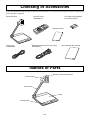
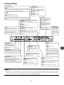
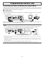
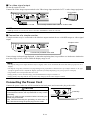
XGA Digital Presenter
DV11G
User’s Manual
English
Introduction
Thank you for purchasing NEC’s XGA digital presenter DV11G ( “this equipment” in
the following).
Connected to a projector, display monitor or TV, this presenter captures images of
documents, teaching materials or other data and shows them large and clear on the
screen.
For safe and proper use of this equipment, please read this user’s manual carefully.
Also, be sure to keep this manual at hand. You can always consult it whenever a
question or trouble arises.
DOC Compliance Notice
This Class B digital apparatus meets all requirements of the Canadian Interference-Causing Equipment Regulations.
Acoustic Noise Information Ordinance-3. GSGV:
The sound pressure level is less than 70 dB (A) according to ISO 3744 or ISO 7779.
RF Interference
WARNING
The Federal Communications Commission does not allow any modifications or changes to the unit EXCEPT
those specified by NEC Soluctions (America), Inc. in this manual. Failure to comply with this government regulation could void your right to operate this equipment. This equipment has been tested and found to comply with
the limits for a Class B digital device, pursuant to Part 15 of the FCC Rules. These limits are designed
to provide reasonable protection against harmful interference in a residential installation. This equipment generates, uses, and can radiate radio frequency energy and, if not installed and used in accordance with the instructions, may cause harmful interference to radio communications. However, there is no guarantee that interference
will not occur in a particular installation. If this equipment does cause harmful interference to radio or television
reception, which can be determined by turning the equipment off and on, the user is encouraged to try to correct
the interference by one or more of the following measures:
• Reorient or relocate the receiving antenna.
• Increase the separation between the equipment and receiver.
• Connect the equipment into an outlet on a circuit different from that to which the receiver is connected.
• Consult the dealer or an experienced radio/TV technician for help.
In UK, a BS approved power cable with moulded plug has a Black (five Amps) fuse installed for use with this equipment.
If a power cable is not supplied with this equipment please contact your supplier.
• Windows Me, Windows 2000 or Windows XP are trademarks or registered trademarks of Microsoft Corporation.
• Other product and company names mentioned in this user’s manual may be the trademarks or registered trademarks of
their respective holders.
E-2
WARNING
Do not use with any power voltage Do not use equipment in places as
other than the indicated voltage.
follows.
The equipment is designed to operate on a power
supply of 100-120 or 200-240 V 50/60 Hz AC. Ensure that your power supply fits this requirement before attempting to use the equipment.
Handle power cord with care.
Handle the power cord carefully.
Damaged cord may cause fire or electric shocks.
• Use only the supplied power cord.
• Do not place any heavy object on the power cord.
• Do not lead the power cord under the equipment
body.
• Do not cover the power cord with a carpet or like
object.
• Do not damage or transform the power cord.
• Do not forcibly bend, twist or pull at the power
cord.
• Do not heat the power cord.
When the power cord is damaged (exposed core,
disconnection, etc.), contact your dealer for replacement.
Do not use the equipment in places as follows. Otherwise fire or electric shocks may occur.
• On a shaky table or in an inclined or unstable position
• Near a heater or in exposure to vibration
• In exposure to moisture or dust
• In exposure to oil mist or steam
• Near a kitchen table or humidifier
Do not allow any foreign matter to
enter equipment.
Do not attempt to insert or drop foreign objects, such
as metal or inflammable objects into the equipment.
Otherwise fire or electric shocks may occur. Take special care when this equipment is used in places where
there are children.
Should any foreign matter have entered the equipment, turn off the power to the equipment first and
then disconnect the power plug from the outlet. Also,
contact your dealer immediately for instructions.
Never open the cabinet.
Disconnect power plug in case of Do not remove or open the cabinet of the equipment.
trouble.
Also, never remodel the cabinet. Otherwise fire or
When the equipment is developing smoke, smell or
noise or when the equipment has been dropped accidentally or the cabinet damaged, turn off the power
to the equipment first and then disconnect the power
plug from the outlet. Fire or electric shocks may occur if you continue to use it. Please contact your
dealer for repair.
electric shocks may occur.
Please contact your dealer for checks, adjustments
or repairs of the equipment inside.
Do not cover the camera head.
Do not cover the camera head with a cloth or other
object. Heating can cause fire.
Do not place equipment where it can Do not touch power plug when you
get wet.
hear thunders.
Do not use the equipment in places where it can get
wet with water (see examples below). Also, never
place a vessel containing water above this equipment. Otherwise fire or electric shocks may occur.
• Do not use this equipment in the rain or snow or
on the shore of an ocean, lake or river.
• Do not use this equipment in the bathroom or
shower room.
• Do not place a vase or flowerpot above this equipment.
• Do not place glasses, cosmetics or chemicals
above this equipment.
Should water or other foreign matter have entered
the equipment, turn off the power to the equipment
first and then disconnect the power plug from the
outlet. Also, contact your dealer immediately for instructions.
Do not touch the power plug when you hear thunders.
Otherwise electric shocks may occur.
E-3
CAUTION
Ground equipment properly.
Do not carry this equipment by camPlease ground the equipment properly for safety rea- era arm or camera head.
sons. See page E-13 for details.
Do not touch power plug with a wet
hand.
Do not carry this equipment by the camera arm or
camera head. Otherwise the camera arm or camera
head may get deformed and break the cord inside
the camera arm, thus causing fire or electric shocks.
Do not connect or disconnect the power plug with a
wet hand. Electric shocks may occur.
Handling of batteries
Do not store equipment by leaning it
against wall or other object.
Do not store the equipment by leaning it against a
wall or other object. It may topple and cause injury.
Be sure to disconnect power cord before carrying equipment.
Handle the batteries with care. Otherwise fire, injuries or pollution may occur.
• Do not allow the batteries shorted, disassembled
or thrown into fire.
• Always use batteries of the specified type.
• Do not use a new and an old battery at the same
time.
• Set the batteries with polarity (+ and –) oriented
correctly as indicated.
When moving this equipment, be sure you have
turned off the power switch, disconnect the power
plug from the outlet and disconnected cables which
are connected to another equipment.
Disconnect power plug when equipment is not used for a long time.
Be sure to disconnect the power plug from the outlet
for safety when the equipment is not to be used for a
long period of time.
Before maintenance, be sure to disconnect power plug.
Before carrying out maintenance, be sure to disconnect the power plug from the outlet as a safety precaution.
E-4
Notes for Use
Do not locate this equipment in a place where it
may be exposed to vibration or shocks.
Do not place this equipment subject to vibration from
any drive system or on board a vehicle or ship. The
vibration or shocks that work on the equipment may
damage the internal parts, which will eventually lead
to a failure. Be sure to use this equipment in places
free from vibration or shocks.
Do not touch the camera lens directly with your
hand. Also, do not use this equipment in a place
containing much dust or cigarette smoke.
Fingerprints or smear on the camera lens will make
normal image shooting impossible.
When the camera lens has become dirty, clean it with
a commercially available camera lens cleaner. In doing so, take care not to damage the lens.
Do not use this equipment near high-voltage lines
or motor power sources.
Use of this equipment near a high-voltage line or motor power source may subject the equipment to interference.
Stage surface
Clean images cannot be obtained if the stage surface is smeared, damaged or discolored. Take care
to protect the stage surface from a splash of any
volatile substance, damage or dirt.
Take adequate measures to prevent external light
from reaching the stage surface.
Make sure that the stage surface is not exposed to
strong light from the outside of the equipment.
Do not leave the equipment in places where the
equipment may be exposed to direct sunshine
or any heating equipment.
Carry the equipment with care.
Please carry the equipment by holding the sides of
the body. Also take care not to give strong shocks to
the body.
When the body becomes dirty, wipe the dirt off
with a well-wrung cloth wetted with a neutral detergent or suchlike and then wipe with a dry cloth.
Do not splash thinner, benzine, insecticide or
other volatile substance on it. Otherwise the
equipment may deform, discolor or develop
trouble. Also never wash the equipment in water, which will lead to a failure.
Disposal
For the disposal of the equipment, please contact
your dealer or your municipality for instructions.
E-5
Contents
Introduction ..................................................................................................................
Safety Notes .................................................................................................................
Notes for Use ...........................................................................................................
Contents .......................................................................................................................
Features .......................................................................................................................
On this Manual .............................................................................................................
E-2
E-3
E-5
E-6
E-7
E-7
Checking of Accessories .............................................................................................. E-8
Names of Parts ............................................................................................................ E-8
Control Panel............................................................................................................ E-9
Back Panel ..............................................................................................................E-10
Remote Control ....................................................................................................... E-11
Preparations before Use .............................................................................................E-12
Connecting the Cable and Setting the Output Mode .............................................. E-12
Connecting the Power Cord ................................................................................... E-13
Setting the Camera Arm ......................................................................................... E-14
How to Use ..................................................................................................................E-14
Turning Power On .................................................................................................. E-14
Shooting the Material (Data) .................................................................................. E-14
Shooting the Surroundings ..................................................................................... E-15
Correcting Trapezoidal Distortion at Oblique Shooting .......................................... E-16
Using Image Memory ............................................................................................. E-17
Transferring Image Memory Contents to PC ...........................................................E-17
Turning Power Off .................................................................................................. E-18
Troubleshooting.......................................................................................................... E-19
Appendixes ................................................................................................................ E-21
Specifications ......................................................................................................... E-21
Dimensions..............................................................................................................E-22
E-6
Features
High image quality and clear image display
Shooting at high image quality of XGA (1024ⴒ768) and displaying clear images
45-power zooming
The optical 15-power and digital 3-power zoom function allows you to enlarge details of the material.
Camera with illumination
The light provided on the camera head allows you to use the space freely.
Rotatable camera head and movable arm
Image shooting in all directions is possible without moving this equipment.
Trapezoidal correction function
Data shot from an oblique direction can be corrected such that it looks as if shot from right above.
Long-life cold-cathode lamp used
Image memory capable of storing eight images
Images can be stored in the body in advance.
You can perform a speedy presentation by switching from camera image to still image from image memory and
back to camera image.
Paper holder function
The material can be held down by a commercially available magnet.
On This Manual
The buttons on the control panel and the remote control are indicated in ‘xx’.
E-7
Checking of Accessories
Check the equipment body and the accessories as shown below. If you find any missing item, please contact your
dealer and get it supplied.
Equipment body
Remote control
(09N999215)
Two SUM-3 (AA) batteries
(for remote control)
Guarantee policy
Power cord
(07N080003)
RGB signal cable (mini D-sub 15-pin)
(07N520001)
User’s Manual (this manual)
Names of Parts
Remote control photoreceiver
Camera head
Camera arm
Stage
Control panel
E-8
Control Panel
WHITE BALANCE
Adjusts the tone of white.
‘AUTO’
Adjusts the tone of white automatically. Before pushing the button,
project a white sheet of paper fully on the screen and adjust the brightness. The indicator lights up during the adjustment.
• Adjust WHITE BALANCE again when the ambient illumination has
changed.
‘BLUE’
Adds a slightly blue shade to white.
‘RED’
Adds a slightly yellow shade to white.
(NOTE) With power to this equipment turned off, white balance will
be reset to factory setting. See page E-15 for storage of adjusted
value.
KEYSTONE
Corrects trapezoidal distortion when shot obliquely. Or cancels correction. (See page E-16)
‘ON / OFF’
Turns trapezoidal correction on or off. The indicator lights up with trapezoidal correction on.
‘+’ ‘-’
Makes fine adjustment of
trapezoidal correction.
SOURCE
Selects a source input for output.
The indicator for the currently selected input
lights up.
‘CAMERA’
Selects camera image.
‘MEMORY’
Selects the image stored in image memory.
(NOTE) Digital zoom is cancelled.
‘EXTERNAL’
Selects the image being inputted to the RGB
input terminal.
(NOTE) EXTERNAL cannot be selected when
video output is selected by dip switch 4. (See
page E-10)
‘LIGHT’
Turns on the light. At each press,
the illumination changes as follows:
“Main light lights up and base light
goes out.” → “Main light goes out
and base light lights up.”→ “Both
main light and base light go out.”
WHITE BALANCE
AUTO
LIGHT
BRIGHTNESS
Adjusts the brightness of image.
‘AUTO’
Adjusts the brightness of image automatically. The indicator lights up
during the adjustment.
‘DARK’
Darkens the image.
‘BRIGHT’
Brightens the image.
BLUE
SOURCE
RED
BRIGHTNESS
CAMERA
MEMORY
AUTO
EXTERNAL
‘REAL / FREEZE’
Selects between
moving image
mode and still image mode. The indicator for the
moving image
mode selected
light up.
KEYSTONE
DARK
FOCUS
BRIGHT
ON/OFF
REAL/FREEZE
ZOOM
UP
MEMORY
DOWN
POSI/NEGA
COLOR/BW
TEXT/PHOTO
‘POSI / NEGA’
Produces an output after
negative conversion.
Press this button again and the
output will return to positive.
The indicator lights up when
positive is on.
‘COLOR / BW’
Produces black-and-white output. Press
again and the output will return to color.
The indicator lights up when color is on.
CAPTURE
AUTO
NEAR
‘CAPTURE’
Writes image into image
memory.
(NOTE) Turning power off
will erase memory contents.
Image Memory No. Display
Displays the No. of the image
memory selected.
‘TEXT / PHOTO’
Selects output for text or photo.
The indicator lights up when text is on.
(NOTE)When the negative mode is selected
using the ‘POSI/NEGA’ button, the ‘TEXT/
PHOTO’ button is not available.
MEMORY
Selects image memory.
‘UP’
Selects the next image memory.
‘DOWN’
Selects the previous image memory.
FAR
WIDE
TELE
ZOOM
Changes the range of image to be
shot.
‘WIDE’
Shoots a wider range.
‘TELE’
Shoots an enlarged portion of an
area.
(NOTE) For zooming above optical 15-power zoom, use digital
zoom. In digital zoom, change
magnification by pressing button
step by step. Digital zoom may
sometimes produce inferior image
quality.
FOCUS
Adjusts the focus of camera image.
‘AUTO’
Adjusts the focus of camera image automatically.
The indicator lights up during the adjustment.
‘NEAR’
Moves the focus nearer to the camera.
‘FAR’
Moves the focus farther from the camera.
NOTE:
• The main light is provided within the camera head. Turn it on when shooting printed matter. The base light is provided
within the stage, which is to be turned on when shooting see-through material. For the combination of ON and OFF of
the lights, please refer to the “lighting guidelines” in the NOTE on page E-15.
E-9
Back Panel
MONITOR Output Terminal
Always displays camera image.
USB Port
Use this terminal when taking the contents of
image memory of this equipment into a PC.
RGB Input Terminal (RGB-IN)
(mini D-sub, 15-pin)
Connect the RGB signal cable when projecting
images from an external image equipment via
this equipment.
RS-232C Terminal
Use this terminal when controlling
this equipment from a PC.
Video Image Output Terminal (VIDEO OUT)
Connect a video cable when displaying images
from this equipment on a TV monitor or the like.
Built-in
Security Slot (
)*
1
2
3 4 5
6 7
8
Dip Switches
OFF
ON
1
2
3
4
5
6
7
8
These switches set the output mode of this equipment. The settings become effective at power on.
Flip the switch up or down, using the tip of a
ballpoint or similar tool.
Dip switches 1 and 2
These switches set the resolution of RGB output.
SW1
SW2
ON
ON
1024ⴒ768 (XGA)
ON
OFF
800ⴒ600 (SVGA)
OFF
ON
640ⴒ480 (VGA)
OFF
OFF
1024ⴒ768 (XGA)
Dip switch 3
This switch selects a signal system outputted from
the Video image output terminal, S-video image
output terminal or Monitor output terminal.
ON
NTSC
OFF
PAL
Dip switch 4
This switch switches between RGB output and
Video output.
ON
Video
OFF
RGB
Dip switch 5
This switch sets output of the RGB monitor output terminal 2.
ON
Outputs the same signal as RGB monitor output terminal 1.
OFF
Outputs signals inputted from RGB
input terminal.
Dip switch 6
This switch selects the setting of white balance
to be turned on at power on.
ON
User adjusted value
OFF
Factory setting
Dip switches 7 and 8
Not used.
Items in a ruled box (
Power Switch
S-video Image Output
Terminal
(S-VIDEO OUT)
Connect an S-video cable
when displaying images
from this equipment on a
TV monitor or the like.
AC IN Terminal
Connect the power cord.
RGB Monitor Output Terminal 2 (RGB-OUT 2)
(mini D-sub, 15-pin)
Always outputs images from the RGB input terminal.
Same output as the RGB monitor output terminal 1
may be produced by Dip switch 5 setting.
RGB Monitor Output Terminal 1 (RGB-OUT 1)
(mini D-sub, 15-pin)
Connect the RGB signal cable when outputting
images from this equipment to a projector or the
like by RGB output.
* This security slot supports the MicroSaver ® Security System. MicroSaver ® is a registered trademark of Kensington Microware Inc. The logo is trademarked and owned by Kensington Microware
Inc.
) indicate factory default settings.
E-10
Remote Control
‘REAL’ Outputs moving images.
Remote Control Transmitter
Transmits infrared remote control signals.
‘FREEZE’ Outputs a still image.
Selects the input to be the source of output.
‘CAMERA’ Selects camera image.
‘EXTERNAL’ Selects image inputted to the RGB input terminal.
(NOTE) ‘EXTERNAL’ cannot be selected when dip switch 4 is selecting
Video.
‘1’ to ‘8’ Selects image memory directly.
Adjusts the focus of camera image.
‘AUTO’ Adjusts the focus of camera image automatically.
‘NEAR’ Moves the focus nearer to the camera.
‘FAR’ Moves the focus farther from the camera.
Adjusts the brightness of image.
‘AUTO’ Adjusts the brightness of image automatically.
‘DARK’ Darkens the image.
‘BRIGHT’ Brightens the image.
Changes the range of image to be shot.
‘TELE’ Shoots an enlarged portion of an area.
‘WIDE’ Shoots a wider range.
䡵 How to set batteries
q Remove the lid of the battery case w Enter the batteries in correct + and – ori- e Place the lid back on.
on the back of the remote control.
entation as indicated on the case inside.
䡵 Effective range
Operate the remote control by directing the remote control transmitter toward the remote control photoreceiver
on the equipment. Signals from the remote control can be received within an approximate range as shown below.
The transmission distance of remote control signals is 4 meters.
30° in upward direction
15° in downward direction
360° in horizontal directions
Notes on the use of remote control:
• The remote control may not function well when the remote control photoreceiver is exposed to direct sunshine, strong
light (inverter fluorescent lamp, strobe light, etc.) or infrared rays. In such a case, change the direction of light or the
equipment body.
• A person or object between the remote control and the remote control photoreceiver may obstruct the transmission/
reception. Also, the transmission/reception may be hindered in the shooting of a surrounding object if the camera head
is turned or the camera arm angle is changed in such a direction as to hide the remote control photoreceiver.
• Handle the remote control with care. Dropping it or giving shock to it may damage the internal structure or electronic
parts.
• Low voltage of the batteries may result in failed transmission. In such a case, replace the batteries with new ones.
E-11
Preparations before Use
Connecting the Cable and Setting the Output Mode
Connect the cable to the equipment that displays the image from this equipment. A selection can be made from
the RGB output and the video output. However, it is necessary to set the output method with the dip switch on the
back panel before turning on the power to this equipment.
䡵 For RGB output
Set the dip switch 4 to OFF.
Connect the RGB monitor output terminal 1 (RGB-OUT 1) to the RGB input terminal of a projector, display or
other image equipment.
Display
Projector
1
2
3 4 5
6 7
8
1 2 3 4 5 6 7 8
Set dip switch 4 to OFF.
Supplied RGB signal cable
With dip switch 5 set to ON, the same signal can be outputted from two systems by connecting a projector or
display to the RGB monitor output terminal 2 (RGB-OUT 2).
NOTE:
• In the case of RGB output only, the RGB output signals from a PC, for instance, may be outputted via this equipment.
For such an application, connect the RGB input terminal to the RGB output terminal on a PC or suchlike.
To a display or projector
1
2
3 4 5
6 7
Set the resolution and frequency of the output signal
of your PC or like device
according to the output
equipment, such as a display or projector.
8
Commercially available RGB cable
To PC or suchlike
• With dip switch 5 set to OFF, the output signal from RGB monitor output terminal 2 is always the same as the signal of
the RGB input terminal.
When it is necessary to frequently switch between camera image and RGB signal, connect the display for PC control to
the RGB monitor output terminal 2 (RGB-OUT 2), then the PC can be controlled while watching the display even when
the camera image is on.
• The settings at dip switches 1 and 2 on the back of the equipment will not be reflected.
• Signals (display screen) inputted from the RGB input terminal of the equipment cannot be stored in memory.
E-12
䡵 For video signal output
Set the dip switch 4 to ON.
Connect the Video image output terminal to the Video image input terminal of a TV or other image equipment.
TV or the like
1
2
3 4 5
6 7
8
1 2 3 4 5 6 7 8
Set dip switch 4 to ON.
Commercially available video cable or S-video cable
NOTE:
• With dip switch 4 set to ON, the source selection ‘EXTERNAL’ cannot be selected.
䡵 Connection of a simple monitor
A simple monitor may be connected to the Monitor output terminal for use with RGB output or video signal
output.
Simple monitor
1
2
3 4 5
6 7
8
Commercially available video cable
Camera image is always being displayed, so that when replacing data, it is possible to see in advance whether the
next data, larger in size, will be within the display range or not.
NOTE:
• The display image on a simple monitor may be slightly wider in the horizontal direction than that of a projector or a
display.
• The display range may sometimes vary depending on the performance characteristics of a simple monitor or the type
of output signals. Please confirm the display position by actually displaying it by your projector or display.
• Trapezoidal correction function does not work.
• Image quality is lower than the image from the RGB monitor output terminal 1/2.
• Image quality may drop and the tone of color may change from the video output terminal.
Connecting the Power Cord
Connect the power cord to the AC IN terminal on the back panel, and connect the plug to the outlet.
CAUTION
Be sure to ground the equipment properly to ensure safety.
To avoid electric shocks, ask a professional to carry out the
grounding.
Be sure to make ground connection before connecting the
power plug to the outlet.
Also, when disconnecting the grounding, be sure to do so
only after disconnecting the power plug from the outlet.
E-13
Insert fully.
AC outlet
Setting the Camera Arm
As illustrated, raise the camera arm gently in the indicated direction while holding the
body down with your hand.
When the angle between the stage and the camera arm is 60 degrees, there is a click with
which the camera arm gets fixed momentarily. Normally use the equipment in this 60degree position. Though the camera arm may be raised to a position of 80 degrees, do
not attempt to raise it any further.
CAUTION
Be sure to hold the body down with your hand when raising
the camera arm.
Otherwise, the body may lift up to cause injury.
60 degrees
(normal position)
How to Use
Turning Power On
POWER
SWITCH
Set the power switch on the back panel to ON ( ).
All the indicators on the control panel light up for about ten seconds.
Shooting the Material (Data)
q Place your material on the stage.
w
w Turn on the main light or turn on the base light, depending on the lighting in the room or the condition of the
material to be shot.
WHITE BALANCE
AUTO
LIGHT
BLUE
SOURCE
RED
CAMERA
MEMORY
EXTERNAL
UP
MEMORY
DOWN
POSI/NEGA
e Determine the size for the zoom shooting.
COLOR/BW
BRIGHTNESS
AUTO
RNAL
r Adjust the focus.
AUTO
KEYSTONE
DARK
FOCUS
NEAR
r
CAPTURE
TEXT/PHOTO
BRIGHT
ON/OFF
REAL/FREEZE
ZOOM
FAR
WIDE
TELE
e
NOTE:
• For shooting a material with many characters, turn on the text mode, which will show the characters clearly for easier
reading.
E-14
Shooting the Surroundings
Turn the camera head toward the object you want to shoot.
Vertical direction
B A
Horizontal direction
Normal position
NOTE:
• The camera head does not turn vertically in your direction (A). Forcible turning may cause trouble.
• For turning in the horizontal direction, do so by holding the part B of the camera head.
NOTE:
• When the material reflects light, turn off the main light. Also, try shooting obliquely by adjusting the camera arm angle.
Lighting Guidelines
Main light *
Base light
Printed matter
ON
OFF
Three-dimensional object
ON
OFF
OHP film and other see-through material
OFF
ON
Reflective material, such as glossy paper
OFF
OFF
* When the room is full of light, better images may be obtained by turning off the main light.
• Adjust the brightness by using both the ON/OFF of the main light and the ‘BRIGHTNESS’ button.
• To store the adjustment of white balance, press the ‘CAMERA’ button three seconds or longer. The adjusted setting is
stored as the indicator of the ‘AUTO’ button of WHITE BALANCE blinks once.
Set dip switch 6 to ON, and the adjusted setting will be turned on at the next power on.
• When changing the material, the scene of the material change can be hidden by turning on a still image by pressing the
‘REAL/FREEZE’ button.
• You can have the material fixed by using a commercially available magnet.
Magnet works here.
E-15
Correcting Trapezoidal Distortion at Oblique Shooting
The trapezoidal correction function can be used to correct trapezoidal distortion that occurs when the camera arm
is moved from the normal position (60°) to a higher position (80°) and material is shot from an oblieque direction.
The wider base is adjusted to the narrower base to obtain an image with reduced distortion.
Use this function when showing a material of A4 vertical size within a screen or when avoiding the reflection of
external light or light from the main light on the material to be shot.
Indicator
60° (normal position)
The indicator of the ‘ON/OFF’ button of KEYSTONE lights up
when the trapezoidal correction function is working. To turn off
the trapezoidal correction function, press the ‘ON/OFF’ button
(indicator going out).
If the trapezoidal correction function has not corrected distortion
completely, make fine adjustment with ‘+’ / ‘-’button of
KEYSTONE.
BRIGHTNESS
AUTO
AUTO
KEYSTONE
DARK
FOCUS
NEAR
BRIGHT
ON/OFF
REAL/FREEZE
ZOOM
FAR
WIDE
TELE
NOTE:
• The trapezoidal correction function does not work when the camera arm is lower than the normal position and material is shot from an oblique direction.
• Turn off the trapezoidal correction function when shooting a solid body from an oblique direction.
• If you adjust the input signal using an auto adjusting function of a projector or display during the operation of the
trapezoidal correction function, the image may not sometimes be displayed properly when the camera arm is returned
to the normal position. In such a case, please carry out the automatic adjustment again.
During the use of trapezoidal correction function:
• Image width narrows.
• Image quality may sometimes drop.
• Magnification of optical zooming lowers.
• Focusing sometimes fails.
E-16
Using Image Memory
You can store images (up to 8 images) in advance and output them later.
䡵 Storing images
q Select the image memory to be used by operating ‘UP’ or
‘DOWN’.
The No. of the image memory selected is displayed by
the indicator.
WHITE BALANCE
LIGHT
AUTO
BLUE
SOURCE
RED
CAMERA
MEMORY
EXTERNAL
UP
MEMORY
DOWN
POSI/NEGA
COLOR/BW
CAPTURE
TEXT/PHOTO
q
w
Indicator
w Press the ‘CAPTURE’ button.
The image is stored in the image memory.
NOTE:
• Image cannot be stored when EXTERNAL or MEMORY has been selected in source selection.
• Capturing during the use of digital zoom will result in the storage of image before the use of digital zoom.
䡵 Outputting images stored in image memory
q Press the ‘MEMORY’ button in source selection.
The contents of the image memory currently selected are
outputted.
Select the image memory by pressing the ‘UP’ or ‘DOWN’
button.
q
WHITE BALANCE
LIGHT
AUTO
BLUE
SOURCE
RED
CAMERA
MEMORY
EXTERNAL
UP
MEMORY
DOWN
POSI/NEGA
COLOR/BW
TEXT/PHOTO
CAPTURE
NOTE:
• Image memories can be selected directly by pressing the buttons ‘1’ to ‘8’ on the remote control.
• The stored images will be deleted by turning power off.
Transferring Image Memory Contents to PC
By the use of a USB cable, the contents of image memory can be transferred to a PC in the form of a JPEG file.
NOTE:
• Transfer of memory contents is only possible to PCs running on Windows Me, Windows 2000 Professional, Windows
XP Home Edition and/or Windows XP Professional and compatible with USB Ver. 1.1.
䡵 Connecting the cable
Connect the square terminal (type B) of the commercially available USB cable (USB standard Ver. 1.1 or equivalent) to the USB port on the back panel.
Connect the other end of the USB cable to the USB port (type A) of your PC.
1
2
3 4 5
6 7
8
E-17
䡵 How to transfer
This equipment will be recognized as the drive by “My Computer” on the PC and the contents of image memory
are displayed as a JPEG file. Copy the JPEG file and transfer it to your PC.
NOTE:
• “U” will be displayed by the indicator for an applicable image memory No. during communication with a PC, such as
when the contents of an image memory are being transferred to the PC.
During the display of “U,” you cannot operate this equipment. Please wait.
• The date and time captured is not stored as data for JPEG file.
• Images captured during the use of the trapezoidal correction function are displayed in the state before correction on a
PC display.
Turning Power Off
Set the power switch on the back panel to OFF (
).
E-18
POWER
SWITCH
Troubleshooting
Before asking for repair, please make the following checks. If you cannot correct the trouble, contact your dealer.
Check for the cause
See page
Power plug is not properly connected to outlet.
Power switch is not on.
Projector or display is not properly connected.
Brightness setting is not correct.
‘EXTERNAL’ or ‘MEMORY’ is selected in source selection. Select ‘CAMERA’.
Mode setting of image is not correct. Set according to projector or display to be
connected.
• Settings of dip switches on back panel are not correct.
E-13
E-14
E-12
E-9
E-9
––
Symptom
Image is not projected. •
•
•
•
•
•
Image is not focused.
• Material is too close to lens (it is 88mm or higher from stage surface).
• ZOOM has been changed after focusing. Carry out focusing with ZOOM set.
• In ‘AUTO’ of focusing, some object may not allow easy focusing.
Adjust by ‘NEAR’ or ‘FAR’ button of FOCUS.
• When projector is used, projector is not properly focused.
Adjust focus as instructed in projector manual.
• Camera image cannot be adjusted when FREEZE mode is selected (‘REAL/
FREEZE’ indicator off) or when ‘EXTERNAL’ or ‘MEMORY’ is selected in source
selection. Turn on REAL mode by pressing ‘REAL/FREEZE’ button, and select
camera image by pressing ‘CAMERA’ button of source selection.
E-10
––
E-14
E-9
––
E-9
Zoom cannot be ad- • Zoom is at down end or up end.
justed.
• Digital zoom is selected.
Change magnification of digital zoom by pressing button step by step.
––
E-9
Image is blurred or dust • Camera lens is dirty. Clean with commercially available camera lens cleaner.
is shown.
––
Image is dark
E-9
E-9
• Main light is not on.
• BRIGHTNESS is not properly adjusted.
Stripes appear in im- • Interference between mesh points of printed matter and image of camera shooting
age of printed matter.
elements may sometimes produce color stripes. In such a case, change image
size a little by ZOOM.
E-9
Color tone is not cor- • White balance is incorrectly adjusted.
rect.
• Negative mode or black-and-white mode is on.
E-9
E-9
Beating appears in im- • Beating may appear in image when equipment is used near source of strong radio
age.
waves. Separate from such source.
––
Image cannot be ad- • Camera image cannot be adjusted when FREEZE mode is selected (‘REAL/
justed.
FREEZE’ indicator off) or when ‘EXTERNAL’ or ‘MEMORY’ is selected in source
selection. Turn on REAL mode by pressing ‘REAL/FREEZE’ button, and select
camera image by pressing ‘CAMERA’ button of source selection.
• There are cases where BRIGHTNESS adjustment cannot raise brightness sufficiently.
E-9
Operation does not oc- • Correct operation may not follow if two buttons are pressed simultaneously or if a
cur at button press.
button is hit in quick succession. Operate buttons one by one with sufficient intervals.
––
Remote control does • Batteries are not set in remote control.
not work.
• Voltage of batteries is low.
• Batteries attached are for operation check only. Use batteries available on the
market.
• Remote control is operated outside usable range.
––
––
––
E-9
E-11
White or black dots ap- • Due to characteristics of moving image high-pixel CCD, white or black dots may
pear in camera image.
appear on rare occasions and can be conspicuous when enlarged by digital zoom.
––
All indicators remain lit • The equipment is in trouble. Contact your dealer for instructions.
even a few minutes after power on.
––
E-19
Symptom
Screen blinks.
Check for the cause
• Darken screen by adjusting brightness to ‘DARK’ side.
Drive does not open • Disconnect USB cable once, turn on power to this equipment and connect USB
when USB-connected.
cable again.
(NOTE) Memory contents will be erased by turning off power to the equipment.
Image distorts into trap- • Indicator of ‘ON/OFF’ button of KEYSTONE is off.
ezoid.
• Make fine adjustment with ‘+’ / ‘-’ button of KEYSTONE.
E-20
See page
E-9
––
E-16
E-16
Appendixes
Specifications
General specifications
Power requirement
Power consumption
Input current
Dimensions
Net weight
100-120/200-240V AC, 50/60 Hz
20W
0.43 A (100-120V AC) / 0.27 A (200-240V AC)
W420mm ⴒ D489mm ⴒ H650mm (service)
W420mm ⴒ D680mm ⴒ H190mm (storage)
5.2 kg
Optical specifications
Lens
Shooting range
Focus adjustment range
Zoom
Focus
Brightness
F1.6-2.6
Max. 344mm ⴒ 252mm (equal to B4)
Min. 16mm ⴒ 12mm
88mm (above stage surface)
Motor-driven, ⴒ 15 (optical), ⴒ 3 (digital)
Auto / Manual
Auto / Manual
Camera specifications
Output operation mode
Camera element
Total number of pixels
Frame rate
Synchronous system
White balance
Input selection
Progressive mode (analog RGB)
• 1024 ⴒ 768 (XGA)
• 800 ⴒ 600 (SVGA)
• 640 ⴒ 480 (VGA)
Interlace mode
• NTSC
• PAL
1/3 inch CCD
850,000 pixels
15 fps
Internal synchronization
Auto / Manual
Possible (built-in camera / External input / Memory 8 images)
I/O terminal specifications
Input terminal
Output terminal
Control terminal
RGB (mini D-sub 15-pin) ⴒ 1
RGB (mini D-sub 15-pin) ⴒ 2
S-video (mini DIN 4-pin) ⴒ 1
Video (RCA-phono) ⴒ 1
Monitor (RCA-phono) ⴒ 1
USB (type B) ⴒ 1
Remote input (mini DIN 8-pin RS-232C female)
Environmental conditions
Operating ambience
Storage ambience
Regulations
Temperature
Humidity
Temperature
Humidity
5°C to 35°C
30% to 80% (no condensation)
-10°C to 50°C
20% to 80% (no condensation)
UL Approved (UL 60950, CSA 60950)
Meets DOC Canada Class B requirements
Meets FCC Class B requirements
Meets AS/NZS3548 Class B
Meets EMC Directive (EN55022:1998, EN55024-1998, EN61000-3-2, EN61000-3-3)
Meets Low Voltage Directive (EN60950, TUV GS Approved)
* These specifications and designs are subject to change without advance notice.
E-21
Dimensions
489
420
650
690
190
62
680
Unit: mm
E-22