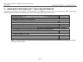
1
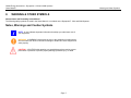
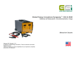
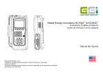
Global Energy Innovations Dynapulse™ 1224 and 3648 Restoration | Conditioner | Charger Systems Users Manual December 2011 Revision 2.0.1 © 2009-2012 Global Energy Innovations, All rights reserved. Printed in the USA. All product names are trademarks of the respective companies. Document: EN-5005-2001 Global Energy Innovations – Dynapulse™ 1224 and 3648 Systems Users Manual 1. Limited Warranty & Limitation of Liability LIMITED WARRANTY & LIMITATION OF LIABILITY Subject to the exclusions contained below, Global Energy Innovations warrants its Dynapulse™ 1224 and 3648 Systems (“Products”), Global Energy Innovations-branded or certified accessories sold for use with these Products (“Accessories”) and Global Energy Innovations software contained on CD-ROMS or other tangible media and sold for use with these Products (“Software”) to be free from defects in materials and workmanship under normal consumer usage for the period(s) outlined below. This limited warranty is a consumer’s exclusive remedy, and applies as follows to new Products, Accessories and Software purchased by consumers, which are accompanied by this written warranty: PRODUCTS COVERED LENGTH OF COVERAGE Products as defined above. One (1) year from the date of purchase by the first consumer purchaser of the product. Accessories as defined above. One (1) year from the date of purchase by the first consumer purchaser of the product. Products or Accessories that are Repaired or Replaced. The balance of the original warranty or for ninety (90) Days from the date returned to the consumer, whichever is longer. Software as defined above. Applies only to physical defects in the media that embodies the copy of the software (e.g. CD-ROM). Ninety (90) days from the date of purchase. What is not covered? (Exclusions) Normal Wear and Tear. Periodic maintenance, repair and replacement of parts due to normal wear and tear are excluded from coverage. Ornamental Decorations. Ornamental decorations such as emblems and graphics, and other decorative elements, are excluded from coverage. Batteries. Only batteries whose fully charged capacity falls below 60% of their rated capacity and batteries that leak are covered by this limited warranty. Abuse & Misuse. Defects or damage that result from: (a) improper operation, storage, misuse or abuse, accident or neglect, such as physical damage (cracks, scratches, etc.) to the surface of the product resulting from misuse; (b) contact with liquid, water, rain, extreme humidity or heavy perspiration, sand, dirt or the like, extreme heat, or food; (c) Subjecting the Product or Accessory to abnormal usage or conditions; or (d) other acts which are not the fault of Global Energy Innovations, are excluded from coverage. Use of Non-Global Energy Innovations Products and Accessories. Defects or damage that result from the use of Non-Global Energy Innovations branded or certified Products, Accessories, Software or other peripheral equipment are excluded from coverage. Unauthorized Service or Modification. Defects or damages resulting from service, testing, adjustment, installation, maintenance, alteration, including without limitation, software changes, or modification in any way by someone other than Global Energy Innovations, or its authorized service centers, are excluded from coverage. i Global Energy Innovations – Dynapulse™ 1224 and 3648 Systems Users Manual Limited Warranty & Limitation of Liability Altered Products. Products or Accessories with (a) serial numbers or date tags that have been removed, altered or obliterated; (b) broken seals or that show evidence of tampering; (c) mismatched board serial numbers; or (d) nonconforming or non- Global Energy Innovations housings, cases, or parts, are excluded from coverage. Software Embodied in Physical Media. No warranty is made that the software will meet your requirements or will work in combination with any hardware or software applications provided by third parties, that the operation of the software products will be uninterrupted or error free, or that all defects in the software products will be corrected. Software NOT Embodied in Physical Media. Software that is not embodied in physical media (e.g. software that is downloaded from the internet), is provided “as is” and without warranty. Who is covered? This warranty extends only to the first consumer purchaser, and is not transferable. What will Global Energy Innovations Do? Global Energy Innovations, at its option, will at no charge repair, replace or refund the purchase price of any Products, Accessories or Software that does not conform to this warranty. We may use functionally equivalent reconditioned / refurbished / pre-owned or new Products, Accessories or parts. No data, software or applications added to your Product, Accessory or Software, including but not limited to personal contacts, site data, configurations, will be reinstalled. To avoid losing such data, software and applications please create a back up prior to requesting service. How to Obtain Warranty Service or Other Information? To obtain service or information, please contact: Your Local Representative or Distributor http://www.globalei.com/distributorsAndReps.html Global Energy Innovations Customer Services Main Phone Number: +1.415.354.5688 Facsimile: +1.415.354.5738 Email: [email protected] Or visit us online at http://www.globalei.com You will receive instructions on how to ship the Products, Accessories or Software, at your expense, to a Global Energy Innovations Authorized Repair Center. To obtain service, you must include: (a) a copy of your receipt, bill of sale or other comparable proof of purchase; (b) a written description of the problem; (c) the name of your distributor or representative, if applicable; and, most importantly; (d) your address and telephone number. What Other Limitations Are There? ANY IMPLIED WARRANTIES, INCLUDING WITHOUT LIMITATION THE IMPLIED WARRANTIES OF MERCHANTABILITY AND FITNESS FOR A PARTICULAR PURPOSE, SHALL BE LIMITED TO THE DURATION OF THIS LIMITED WARRANTY, OTHERWISE THE REPAIR, REPLACEMENT, OR REFUND AS PROVIDED UNDER THIS EXPRESS LIMITED WARRANTY IS THE EXCLUSIVE REMEDY OF THE CONSUMER, AND IS PROVIDED IN LIEU OF ALL OTHER WARRANTIES, EXPRESS OF IMPLIED. IN NO EVENT SHALL GLOBAL ENERGY INNOVATIONS BE LIABLE, WHETHER IN CONTRACT OR NOT (INCLUDING NEGLIGENCE) FOR DAMAGES IN EXCESS OF THE PURCHASE PRICE OF THE PRODUCT, ACCESSORY OR SOFTWARE, OR FOR ANY INDIRECT, INCIDENTAL, SPECIAL OR CONSEQUENTIAL DAMAGES OF ANY KIND, OR LOSS OF REVENUE OR PROFITS, LOSS OF BUSINESS, LOSS OF INFORMATION OR DATA, SOFTWARE OR APPLICATIONS OR OTHER FINANCIAL LOSS ARISING OUT OF OR IN CONNECTION WITH THE ABILITY OR INABILITY TO USE THE PRODUCTS, ACCESSORIES OR SOFTWARE TO THE FULL EXTENT THESE DAMAGES MAY BE DISCLAIMED BY LAW. ii Global Energy Innovations – Dynapulse™ 1224 and 3648 Systems Users Manual Limited Warranty & Limitation of Liability Some states and jurisdictions do not allow the limitation or exclusion of incidental or consequential damages, or limitation on the length of an implied warranty, so the above limitations or exclusions may not apply to you. This warranty gives you specific legal rights, and you may also have other rights that vary from state to state or from one jurisdiction to another. Laws in the United States and other countries preserve for Global Energy Innovations certain exclusive rights for copyrighted Global Energy Innovations software such as the exclusive rights to reproduce and distribute copies of the Global Energy Innovations software. Global Energy Innovations software may only be copied into, used in, and redistributed with, the Products associated with such Global Energy Innovations software. No other use, including without limitation disassembly of such Global Energy Innovations software or exercise of the exclusive rights reserved for Global Energy Innovations, is permitted. iii Global Energy Innovations – Dynapulse™ 1224 and 3648 Systems Users Manual Table of Contents 2. TABLE OF CONTENTS 1. LIMITED WARRANTY & LIMITATION OF LIABILITY ................................................................................................................................................................. i 2. TABLE OF CONTENTS .............................................................................................................................................................................................................. 1 3. DECLARATION OF CONFORMITY ........................................................................................................................................................................................... 2 4. COPYRIGHT NOTICE ................................................................................................................................................................................................................ 3 5. SAFETY INSTRUCTIONS – INTRODUCTION .......................................................................................................................................................................... 4 6. SAFETY PRECAUTIONS ........................................................................................................................................................................................................... 5 7. CAUTION & WARNING STATEMENT ....................................................................................................................................................................................... 6 8. WARNING & OTHER SYMBOLS ............................................................................................................................................................................................... 7 9. IMPAIRED SAFETY .................................................................................................................................................................................................................... 8 10. LIST OF WARNINGS & SAFETY PRECAUTIONS – GENERAL SAFETY INFORMATION ..................................................................................................... 9 11. UNPACKING THE DYNAPULSE™ 1224 & 3648 SYSTEM KITS............................................................................................................................................ 11 12. INTRODUCTION ....................................................................................................................................................................................................................... 12 13. DYNAPULSE 1224 & 3648 SYSTEMS – QUICK START INSTRUCTIONS) ........................................................................................................................... 13 14. PREPARATION FOR USE ....................................................................................................................................................................................................... 14 15. PRINCIPLES OF OPERATION (TECHNOLOGY BACKGROUND) ......................................................................................................................................... 15 16. OPERATING INSTRUCTIONS ................................................................................................................................................................................................. 18 17. MAINTENANCE AND SERVICING (PREVENTATIVE & CORRECTIVE) ............................................................................................................................... 30 18. PREPARATION FOR SHIPPING ............................................................................................................................................................................................. 35 19. STORAGE ................................................................................................................................................................................................................................. 36 20. DYNAPULSE™ 1224 & 3648 SPECIFICATION....................................................................................................................................................................... 37 Page 1 Global Energy Innovations – Dynapulse™ 1224 and 3648 Systems Users Manual 3. Declaration of Conformity DECLARATION OF CONFORMITY Based on the test results using appropriate standards, the Dynapulse™ 1224 and 3648 Systems are in conformity with the following: EN 61000-6-3:2007 EN 61000-6-1:2007 Conformity is indicated by the CE symbol (“Conformité Européenne). Page 2 Global Energy Innovations – Dynapulse™ 1224 and 3648 Systems Users Manual 4. Copyright Notice COPYRIGHT NOTICE Information in this document is subject to change without notice. © Global Energy Innovations. All rights reserved. Reproduction in any manner whatsoever without the written permission of Global Energy Innovations is strictly forbidden. No Warranty. This user manual is being delivered to you “as is” and Global Energy Innovations makes no warranty as to its accuracy or use. Any use of this documentation or the information contained therein is at the risk of the user. This documentation may include technical or other inaccuracies or typographical errors. Global Energy Innovations reserves the right to make changes without prior notice. Although every effort has been made to assure the accuracy of the representations of the Dynapulse 1224 and 3648 screen displays within this manual, last minute changes and alterations may lead to slight differences in the information held within this manual and the actual display. Trademarks Global Energy Innovations, The GEI logo, Dynapulse™, IBMS™, CELScan™ are trademarks of Global Energy Innovations. Page 3 Global Energy Innovations – Dynapulse™ 1224 and 3648 Systems Users Manual 5. Safety Instructions – Introduction SAFETY INSTRUCTIONS – INTRODUCTION Read these pages carefully before beginning to install, unpack or use the Dynapulse™ 1224 and/or 3648 Systems. The following paragraphs contain information, cautions and warning which must be followed to ensure safe operation and keep the Dynapulse™ System in safe condition. WARNING Servicing described in this manual is to be done ONLY by qualified service personnel. To avoid electrical shock, DO NOT service the Dynapulse™ System unless you are qualified to do so. WARNING DO NOT use the Dynapulse™ System unless you have been formally trained at servicing electrical power systems including battery and other energy storage devices. Page 4 Global Energy Innovations – Dynapulse™ 1224 and 3648 Systems Users Manual 6. Safety Precautions SAFETY PRECAUTIONS For the correct and safe use of the Dynapulse™ 1224 and 3648 Systems, it is essential that both operating and service personnel follow generally accepted safety procedures in addition to the safety precautions specified in this manual. Specific warning and caution statements, where they apply, will be found throughout the manual. Where necessary, the warning and caution statements and/or symbols are marked on the Dynapulse™ 1224 and 3648 Systems. Page 5 Global Energy Innovations – Dynapulse™ 1224 and 3648 Systems Users Manual 7. Caution and Warning Statement CAUTION & WARNING STATEMENT WARNING Used to alert the user to the possibility of performing an incorrect maneuver which could lead to damage or destruction of the equipment or other property. CAUTION Used to call attention to a potential danger that requires correct procedures or practices to prevent property damage, personal injury, or death. Page 6 Global Energy Innovations – Dynapulse™ 1224 and 3648 Systems Users Manual 8. Warning and Other Symbols WARNING & OTHER SYMBOLS Nomenclature and Formatting in this Manual The following safety symbols are used in the Users Manual, or on labels on the Dynapulse™ 1224 and 3648 Systems. Notes, Warnings and Caution Symbols NOTE: A note indicates important information that helps you make better use of your equipment. WARNING: A WARNING used to alert the user to the possibility of performing an incorrect maneuver which could lead to damage or destruction of the equipment or other property. CAUTION: A CAUTION calls attention to a potential danger that requires correct procedures or practices to prevent property damage, personal injury, or death. Page 7 Global Energy Innovations – Dynapulse™ 1224 and 3648 Systems Users Manual 9. Impaired Safety IMPAIRED SAFETY Whenever it is likely that safety has been impairs, the Dynapulse™ System must be turned off and disconnected from the line power. The matter should be referred to a qualified technician. Safety is likely to be impaired if, for example, the Dynapulse™ System fails to perform the intended procedure or shows visible damage. Page 8 Global Energy Innovations – Dynapulse™ 1224 and 3648 Systems Users Manual List of Warnings and Safety Precautions – General Safety Information 10. LIST OF WARNINGS & SAFETY PRECAUTIONS – GENERAL SAFETY INFORMATION Please read all of the following Warnings before operating your Dynapulse™ 1224 or 3648 Systems. GENERAL SAFETY INFORMATION CAUTION Removing the Dynapulse™ System covers or removing parts, is likely to expose live parts and accessible terminals which can be dangerous to life. WARNING / AND SAFETY PRECAUTIONS 1. NEVER leave the Dynapulse™ System unattended while in operation. A live person must be present during operation to shut the unit off or disconnect the battery if there are any unexpected battery faults. There are battery fault modes that can lead to thermal runaway. 2. Do not use or operate the Dynapulse™ Systems (1224 and 3648) unless you have been formally trained at servicing electrical power systems including battery and other energy storage devices. 3. Before using the Dynapulse™ System, be sure to read all instructions and CAUTIONS in this manual, printed on the unit, and on the battery. 4. Before using the Dynapulse™ System, read all instructions and cautionary markings on 1) the Dynapulse™ System, 2) the battery and 3) the product that uses the battery. 5. The Dynapulse™ System must be disconnected from all voltage sources before it is opened. 6. Capacitors inside the System can hold their charge even if the System has been separated from all voltage sources. 7. When servicing the Dynapulse™ System, use only specified replacement parts. 8. The Dynapulse™ Systems (1224 and 3648) use high voltages internally. Once connected to a normal battery, the battery limits the voltage to a safe value. Disconnecting the Dynapulse™ System, however, while it is running may cause high voltages to be present in the battery cables and clips. NEVER disconnect the Dynapulse™ System from a battery without first turning it off or pushing the STOP button. DO NOT touch the battery terminals or Dynapulse™ clips while the System is running. 9. Hydrogen gas can be present near batteries that are charging and operating on the Dynapulse™ System. Always operate your System in a well-ventilated area. NEVER smoke or allow a spark or flame in the vicinity of the battery. 10. It is recommended that you have baking soda (NaHCO3) and water available to absorb (neutralize) any battery electrolyte that may leak or bubble from the battery. 11. Have plenty of fresh water and soap nearby in case battery acid contacts skin, clothing or eyes. 12. Wear complete eye protection and clothing protection and always avoid touching your eyes while working near lead acid batteries. Page 9 Global Energy Innovations – Dynapulse™ 1224 and 3648 Systems Users Manual List of Warnings and Safety Precautions – General Safety Information 13. If battery acid contacts your skin or clothing, wash immediately with soap and water. If acid enters your eyes, immediately flood eyes with running cold water for at least 10 minutes and get medical attention immediately. 14. When using the Dynapulse™ on a battery that is still mounted in equipment (i.e. a vehicle, generator, other), disconnect the battery from the equipment and electrical / electronic system. Failure to do so may result in damage to the electrical system of your equipment. 15. DO NOT service or repair battery connections on a charged battery when the circuit is energized. 16. If you are using an extension cord (power line) with your Dynapulse™ System, ensure that the cord meets safety requirements. Also ensure the wire gauge is sufficient for the AC current rating. The Dynapulse™ requires up to 15 Amps. 17. NEVER operate the Dynapulse™ System with a damaged AC cord or DC cables. Replace any damaged cords or cables. 18. DO NOT disassemble the Dynapulse™ System except as specified in this Users Manual. Contact your local distributor or the manufacturer for any repairs, inspections or calibrations. Improper reassembly may result in electrical shock, fire or damage to the unit. 19. When using the Dynapulse™ System, locate the unit as far away as possible from the battery as the DC cables allow. 20. DO NOT expose the Dynapulse™ System to rain, snow or other harsh environmental conditions. 21. NEVER operate the Dynapulse™ System on a frozen (very cold) battery. If the battery electrolyte is frozen or very cold, bring the battery into a warm area and allow complete thawing before operating. 22. DO NOT allow the Dynapulse™ DC battery clips (alligator clamps) to touch each other when the System is on. 23. Remove all personal metal items (i.e. necklaces, rings, watches, bracelets, etc.) when working with lead-acid batteries and the Dynapulse™ System. Batteries can produce a short circuit current high enough to vaporize or melt a ring (or similar). 24. Take precautions to NOT drop any metal tools onto the battery or battery terminals. Metal can cause sparking or short circuit battery or other electrical devices. All tools used in or around a battery should be properly insulated. 25. Before using the Dynapulse™ System, ensure that someone is within range of your voice or close enough to come to your aid when you work near a leadacid battery. NEVER UNDER ANY CIRCUMSTANCES ATTEMPT TO CHARGE A 2, 4, 6 OR OTHER VOLTAGE BATTERY THAT IS NOT SUPPORTED BY THE DYNAPULSE™ 1224 OR 3648 DYNAPULSE™ SYSTEM. THIS WILL RESULT IN SERIOUS DAMAGE TO THE BATTERY AND CREATE A RISK OF EXPLOSION. IMPROPER CONNECTION CAN RESULT IN EXPLOSION AND SERIOUS INJURY. WORKING IN THE VICINITY OF A LEAD-ACID BATTERY IS DANGEROUS. BATTERIES GENERATE EXPLOSIVE GASES DURING NORMAL BATTERY OPERATION. FOR THIS REASON, IT IS OF THE UTMOST IMPORTANCE THAT EACH TIME BEFORE USING YOUR DYNAPULSE™ SYSTEM, YOU READ THIS MANUAL AND FOLLOW THE INSTRUCTIONS EXACTLY. Page 10 Global Energy Innovations – Dynapulse™ 1224 and 3648 Systems Users Manual Unpacking the Dynapulse ™ 1224 & 3648 System Kits 11. UNPACKING THE DYNAPULSE™ 1224 & 3648 SYSTEM KITS The following items are included in the Dynapulse™ 1224 and 3648 System kits. TABLE 1 is a complete list of the Various Dynapulse™ System Kits including all standard and optional accessories as well as replacement parts, product upgrade and warranty extension options. Dynapulse™ 248 | 1224 | 3648 Model Battery Restoration / Conditioner / Charger Systems PART NUMBER EQUIPMENT – Dynapulse™ (1224): 8656-5002 Dynapulse 1224™ System 8656-5002 Dynapulse 3648™ System 8656-5003 Hard Carrying / Transportation Protective Case 8600-5001 EQUIPMENT – Dynapulse™ (3648: 8656-5003 EQUIPMENT – OPTIONAL ACCESSORIES REPLACEMENT PARTS (Ship Standard with 1224 (8656-5002) and 3648 (8656-5003) 5 Foot (1.53 Meters), 6 Gauge Output Cable with Clamps High Current AC Wall Plug (15 Amp, 125 VAC) 8600-5005 1010-5001 Calibration / Certification - Yearly with Certificate Extended Warranty - 1 Year Extension Extended Warranty - 2 Year Extension 8740-5001 8740-4001 8740-4002 PRODUCT WARRANTY & OTHER TABLE 1. Listing of all Dynapulse™ System Kits including all standard and optional accessories as well as replacement parts, product upgrade and warranty extension options. Page 11 Global Energy Innovations – Dynapulse™ 1224 and 3648 Systems Users Manual Introduction 12. INTRODUCTION Please read all of the following Warnings before operating your Dynapulse™ 1224 or 3648 Systems. The Dynapulse™ 1224 and 3648 Systems are designed for restoring, conditioning and charging 12 and 24 Volt (1224) and 36 and 48 Volt (3648) lead acid batteries of any capacity size. Although it works on large capacity batteries, it is especially suited for golf cart, utility electric vehicle, starting lighting ignition (SLI) and other moderate to small lead acid batteries in the rage of 50-200 Amp-Hours. Lead acid batteries are happiest when they are fully charged. As the battery discharges, lead sulfate (PbSO4) is deposited as an oxide onto the plates. This is normal. When the battery is recharged, the lead sulfate is transformed back to lead and sulfuric acid (H2SO4) on the negative plates. When the battery is left in a low state of charge and the lead sulfate is left undisturbed, ripening (growth) of the lead sulfate crystal occurs which ultimately impedes the future recharging of the battery. If the time between charges is not long and the battery is not left a very low state of charge, the lead sulfate can be easily returned to the electrolyte and recovered. Batteries that have not been charged for long periods of time will often not accept charge and consequently suffer from premature capacity fade (loss). The Dynapulse™ Systems allow for the rapid recovery and conditioning of batteries that have excessive, reversible sulfation and prevent irreversible capacity loss due to this sulfation. It should be noted that some batteries that have excessive, irreversible sulfation will not be recoverable with the Dynapulse™ System. These batteries have passed their usable service life and must be replaced. The Dynapulse™ weighs approximately 50 lbs (18.6 kg). It is provided with wheels and a handle for easy movement. The unit is supplied with an AC power cord for North America (115 VAC) line voltage. The unit can be configured for 230 VAC operation. When configured for 230 VAC, an IEC320, C13 cord is required. Instructions for changing from 115 VAC to 230 VAC are provided in this Users Manual. The unit is supplied with a DC battery cable that has battery post clamps (alligator clamps) on one end and a mating connector that attaches to the Dynapulse™ System on the other end. No tools or other equipment are required to operate the Dynapulse™ System. The Dynapulse™ System is a ventilated electronic system and must be used and stored in a dry, indoor environment. Page 12 Global Energy Innovations – Dynapulse™ 1224 and 3648 Systems Users Manual Quick Start Instructions 13. DYNAPULSE 1224 & 3648 SYSTEMS – QUICK START INSTRUCTIONS) Please read the safety instructions in this Users Guide before operating the Dynapulse™ 1224 or 3648 Systems. 1. The Dynapulse™ Systems (1224 and 3648) use high voltages internally. Once connected to a normal battery, the battery limits the voltage to a safe value. Disconnecting the Dynapulse™ System, however, while it is running may cause high voltages to be present in the battery cables and clips. NEVER disconnect the Dynapulse™ System without first turning it off or pushing the STOP button. DO NOT touch the battery terminals for Dynapulse™ clips while the System is running. 2. Connect the Dynapulse™ System to a power line rated for 15 Amps at 115 VAC. For operation at 220 VAC, please refer to this Users Manual to change the factory settings from 1150 VAC to 220 VAC before proceeding. 3. Connect the DC clamps (alligator clamps) to the battery. The RED clamp goes to battery positive (+) and the BLACK clamp goes to battery negative (-). If there is a beep and a red, flashing light from the Dynapulse™ System, you have connected the battery clamps backwards (revered polarity). This must be corrected for the Dynapulse™ System to run. 4. Turn on the Dynapulse™ System using the large, white rocker switch in the lower right of the front panel. Observe that battery open-circuit voltage on the Voltage Display. 5. IMPORTANT – Select the proper battery voltage setting on the Dynapulse™ System front panel. Dynapulse™ 1224 – Use 12 Volt for 6-Cell Batteries and 24 Volt for 12-Cell Batteries. Dynapulse™ 3648 – Use 36 Volt for 18-Cell Batteries and 48 for 24-Cell Batteries. 6. Select the Battery Size using the selector switch. This will change the peak conditioning current pulse amplitude. 7. Press the START button until the green CHARGING light comes on. This may take a couple of seconds. Release the START button. 8. The Dynapulse™ System will condition and charge the battery until the battery current falls below 4.0 Amps for two hours, or for eight hours after the START button is pressed. 9. NEVER leave the Dynapulse™ System unattended while in operation. A live person must be present during operation to shut the unit off or disconnect the battery if there are any unexpected battery faults. Battery temperature must be monitored on a regular basis to ensure there are not any hot-spots developing in the battery due to faulty cells. There are battery fault modes that can lead to thermal runaway. For extra added safety, while in operation, a Dynapulse™ 24-Input Temperature Monitoring Block accessory may be used. This accessory allows the user to monitor temperature at 24 different locations on a battery while testing is occurring. If the accessory is used in the appropriate fashion, excessive battery temperature will automatically trigger the Dynapulse™ to shut down. Page 13 Global Energy Innovations – Dynapulse™ 1224 and 3648 Systems Users Manual Preparation for Use 14. PREPARATION FOR USE The Dynapulse™ Systems are packed in multiple cardboard boxes with cushioning foam or shipped in a Hard Carrying / Transportation Protective Case (Optional Accessory – P/N 8600-5001). Inspect the shipping box for damage before accepting the unit from the shipper. Unpack the unit and inspect for obvious mechanical damage. Not any rattling or loose parts when the unit is tilted on its wheels. If there is any rattling, DO NOT operate the equipment until it has been examined by a qualified repair facility. If possible, retain the packing material in the event the Dynapulse™ System must be returned to the factory for maintenance, repair, calibration or other. Due to the large mass (weight) of the Dynapulse™ Systems, shipping damage is very common when not properly prepared and not shipped with a qualified shipping company. Page 14 Global Energy Innovations – Dynapulse™ 1224 and 3648 Systems Users Manual Principles of Operation (Technology Background) 15. PRINCIPLES OF OPERATION (TECHNOLOGY BACKGROUND) 15.1. Conversion from Line Voltage The input line voltage is turned on using the front-panel circuit breaker / power switch. The AC line voltage is converted through a transformer and rectifiers to two, 35-VDC sources (Dynapulse™ 1224) or 60-VDC sources (Dynapulse™ 3648) and stored in large storage capacitors. Under microprocessor control, these two sources are tied in parallel on the Dynapulse™ 1224 for use on a 12-Volt battery, or in series for use on a 24-Volt battery. For the Dynapulse™ 3648, the two sources are tied in parallel for use on a 36-Volt battery, or in series for use on a 48-Volt battery. The high internal voltage helps to force a high-current pulse into the battery even if it is severely sulfated. 15.2. Current Pulsing Technique High-power transistors connect the storage capacitors to the battery for short pulses under microprocessor control. A series ballast resistor limits the current into the battery to avoid damage to the battery plates. These transistor pulse at 100 ~ 120 pulses per second. It has been observed that desulfation proceeds most rapidly with this range of pulse rate (Patented). Other researchers1,2,3 have published findings that there are significant benefits with pulsed-current techniques. A summary of the benefits are detailed below: 15.3. An order of magnitude reduction in charging time An increase in cycle life by a factor of 3-4. Recovery of capacity of heavily cycled cell. Effective means for delaying the progressive increase in the crystallization process in the active material (which causes capacity loss) as well as the minimization of the growth of the resistive PbO layer immediately adjacent to the grid. Average Current Control The peak current pulses are responsible for most of the work associated with desulfation of the battery. The average (charging) current both charges the battery as well as causes gassing (bubbles) at the plate / electrolyte interface allowing good electrolyte mixing. The average current provided by the Dynapulse™ Systems and accepted by the battery, is directly proportional to the power taken from the AC power line. Consequently, too great an average current will cause the AC power line circuit breaker to trip. An average current control knob on the front panel is used to reduce the average current if circuit breaker tripping is a problem. 1 L.T. Lam, H. Ozgun, O.V. Lim, J.A. Hamilton, L.H. Vu, D.G. Vella and D.A.J. Rand, Pulsed-current charging of lead/acid batteries – a possible means for overcoming premature capacity loss, Journal of Power Sources, 53 (1995), 215-228. 2 G. Yonglang, R. Groiss, H. Doring and J. Garche, Rate-Determining Step Investigations of Oxidation Processes at the Positive Plate during Pulse Charge of Valve-Regulated Lead-Acid Batteries, Journal of Electrochemical Society, 146(11), (1999), 3949-3957. 3 J.J.A. Wilkinson and G.A. Covic, A new pulse charging methodology for lead acid batteries, IPENZ Transactions, Vol. 25, No.1/EMCh, 1998. NOTE: These and similar “Technology Background” publications can be found on the Global Energy Innovations, Customer Support Site (http://support.globalei.com). Page 15 Global Energy Innovations – Dynapulse™ 1224 and 3648 Systems Users Manual Principles of Operation (Technology Background) The microprocessor adjusts the transistor on-time pulse widths to regulate the average current as set by the front panel knob. The range is approximately 11-15 Amps of current into the battery. At 24 VDC (Dynapulse™ 1224) and 48 VDC (Dynapulse™ 3648) output with 115 VAC line input, approximately 11-15 Amps of line current will flow. At the lower VDC setting (12 VDC and 36 VDC) for the various Dynapulse™ Systems, the AC line current is roughly half the indicated average battery current. CAUTION – Never use the Dynapulse™ System on an AC power line that is not properly rated. 15.4. Voltage Control If the Dynapulse™ System is connected to a “good”, charged battery, or if it is left connected overnight to a lightly sulfated battery, it will top charge the battery after mild conditioning and restoration. The microprocessor constantly monitors the battery voltage and regulates the transistor on-time pulse width to limit the open-circuit battery voltage to a safe value. This prevents battery overcharge and the resulting damage to the battery. CAUTION – Always ensure you have selected the correct Battery Voltage using the Battery Voltage Selector. Failure to do so may result in damage to your battery, excessive battery heating, thermal runaway and possibly battery fire or explosion. 15.5. End of Charge The battery current is immediately monitored after the START button is pressed. A heavily sulfated battery or a fully-charged battery may refuse to accept charge, or may accept a very low average charge current. Even a fully-charge battery will accept a high charge current for a short period of time (several seconds or minutes) when first connected, where a heavily sulfated battery will not. The battery charge current, which is continually monitored by the microprocessor, must exceed 9.0 Amps to “Qualify” the battery as being healthy and suitable for accepting a normal charge. When the following three conditions are met the Dynapulse™ System turns off all charging current and displays a DONE light: The battery reaches it maximum allowed voltage. The battery’s charge rate has exceeded the 9.0 Amps “Qualifying” current. The charge current has decreased below a 4.0 Amps set minimum. The fans continue to run and the front panel voltmeter continues to show battery voltage. If the Dynapulse™ System times our, or if the current drops below 4.0 Amps without ever exceeding the 9.0 Amps “Qualifying” current, the System will turn off charging current but the DONE light will not illuminate. 15.6. Timeout The Dynapulse™ Systems have an 8-hour, built-in timer. After the START button is pressed, the Dynapulse™ Systems will charge a battery for up to 8 hours (± 15 minutes). If a longer charging period is needed (forklift, industrial backup, utility and other large capacity batteries), the STOP and then START button must be pressed again at least every 8 hours. 15.7. Overtemperature Page 16 Global Energy Innovations – Dynapulse™ 1224 and 3648 Systems Users Manual Principles of Operation (Technology Background) The Dynapulse™ Systems have temperature sensors built into the battery clamps for accurately measuring post and internal battery temperature. If either battery terminal exceeds 50°C (122°F), the Dynapulse™ System output current will shut off. Both the ammeter and voltmeter will display all dashes [---] and all front panel indicators (LEDs) will flash. The Dynapulse™ System must be power cycled (Turned OFF then back ON) to reset this overtemperature fault condition. If the power on the Dynapulse™ System is turned back before the battery clamps has cooled to below 50°C (122°F), the System will not output current. NEVER leave the Dynapulse System unattended while in operation. A live person must be present during operation to shut the unit off or disconnect the battery if there are any unexpected battery faults. Battery temperature must be monitored on a regular basis to ensure there are not any hot-spots developing in the battery due to faulty cells. There are battery fault modes that can lead to thermal runaway. For extra added safety, while in operation, a Dynapulse 24-Input Temperature Monitoring Block accessory may be used. This accessory allows the user to monitor temperature at 24 different locations on a battery while testing is occurring. If the accessory is used in the appropriate fashion, excessive battery temperature will automatically trigger the Dynapulse to shut down. 15.8. Reverse Battery (Polarity Correction) & Low Voltage Alarms CAUTION – Connecting a charging source to any battery backwards, this is, with the positive of the charger feeding into the negative pole of the battery, can destroy the battery. Depending of the charger design and the battery capacity (size), the delivered energy can cause the battery to explode or bubble violently and vent electrolyte. For this reason, the Dynapulse™ systems monitor the battery connection as a safety measure for detection of reverse polarity. A battery connected properly (polarity), with at lease 2 Volts (12-Volt Setting – Dynapulse™ 1224), or 4 Volts (24-Volt Setting – Dynapulse™ 1224), or 6 Volts (36-Volt Setting – Dynapulse™ 3648), or 12 Volts (48-Volt Setting – Dynapulse™ 3648) terminal voltage must be detected or the Dynapulse™ Systems will not apply power to the DC battery cable. If one of the above conditions is not met, the REVERSED ERROR! LED indicator will illuminate and an alarm (Beeper) will sound, even with no other power applied to the Dynapulse™ System. Additionally, when the Dynapulse™ System is turned on, the red light will flash rapidly any time the output is below 6 Volts. Page 17 Global Energy Innovations – Dynapulse™ 1224 and 3648 Systems Users Manual Operating Instructions 16. OPERATING INSTRUCTIONS 16.1. Front-Panel: Controls and Indicators FIGURE 16.1.1. Front-Panel control and indicators. Page 18 Global Energy Innovations – Dynapulse™ 1224 and 3648 Systems Users Manual I.D. Operating Instructions CONTROL / INDICATOR FUNCTION / USE (DESCRIPTION) Amber Light – When illuminated, Indicates battery is NOT accepting peak charge current. 1 Sulfated Battery Indicator 2 Output Voltage All LEDs Flashing (1, 4, 5 and 11) – Indicates that the batter has exceeded its overtemperature limit of 50°C (122°F). See Section 15 for details on this fault condition. Meter – Displays average output voltage (Volts). When Dynapulse™ is not running, displays battery Open Circuit Voltage (OCV). Knob – 3 Battery Voltage Selector Dynapulse™ 1224 Selects between 12 and 24 VDC battery output. Dynapulse™ 3648 Selects between 36 and 48 VDC battery output. WARNING: Always ensure you have set this selector to the proper battery voltage prior to starting. Green Light – Indicates battery charge has completed normally and system has disconnected been disconnected from the battery. This is only for completion of charge. 4 Done Indicator Indicator will not illuminate if shutdown if from: The 8-Hour timeout after starting. Manual shutdown If the battery never accepted a “Qualifying” charge of 9.0 Amps (See Section 10 for details). All LEDs Flashing (1, 4, 5 and 11) – Indicates that the batter has exceeded its overtemperature limit of 50°C (122°F). See Section 15 for details on this fault condition. Red Light (Continuous) – When System is unpowered, a continuous Red indicator (accompanied with an audible alarm – Beep) indicates a Reversed battery connection (polarity error). 5 Reversed Battery (Polarity) Indicator Red Light (Blinking) – When powered a Red blinking light indicates no good battery connection is found or that a serious internal error has occurred. All LEDs Flashing (1, 4, 5 and 11) – Indicates that the batter has exceeded its overtemperature limit of 50°C (122°F). See Section 15 for details on this fault condition. 6 Start Push-Button Button – After connecting to the battery, push to start the System. 7 DC Battery Cable Connector This connector is used to connect the Dynapulse™ System to battery to be conditioned via the DC Battery Cable with Alligator Clamps. Page 19 Global Energy Innovations – Dynapulse™ 1224 and 3648 Systems Users Manual Operating Instructions 8 AC Power-On Indicator Amber Light – Indicates the System is connected to AC Power and is on. This indicator does not indicate that a battery connection has been made. 9 Average Output Current (A) Meter – Displays average output current (Amps) when the Dynapulse™ is running. 10 Battery Size Selector Knob – Selects between a small (less than 60-Amp-Hour) and large (greater than 60 Amp-Hour) battery. Green Light – Indicates that bulk charging is in progress. 11 Charge Indicator 12 Average Current Control Knob – Controls the average output current and consequently the average AC input line current. This control is used to prevent (reduce AC current load) tripping the AC line circuit breaker. 13 Stop Push-Button Button – Push to stop the System before disconnecting the battery. This also resets the internal 8-Hour timer. 14 System Power Switch Switch – This Circuit Breaker (2-Pole, 20 Amp) controls all power to the Dynapulse™ System and protects against internal faults. All LEDs Flashing (1, 4, 5 and 11) – Indicates that the batter has exceeded its overtemperature limit of 50°C (122°F). See Section 15 for details on this fault condition. TABLE 16.1.1. Listing of all Dynapulse™ System Controls and Indicators on the Front-Panel. 16.2. Environmental The Dynapulse™ Systems require free air circulation for internal cooling. The Systems MUST be operated and stored in a dry, sheltered environment. The Systems should only be operated in the following environmental conditions. Failure to do so may result in System damage or faulty operation. Temperature: 0°C to 50°C (32°F to 122°F). Elevation: See level to 10,000 Feet. Note: At 10,000 feet elevation, the cooling fans are only approximately ⅔ as effective as at see level. Humidity: 0 to 95% non-condensing. WARNING – It is very dangerous to attempt to charge a frozen battery. Be sure to check for this condition if operating in freezing temperatures. 16.3. Initial Setup 1. Determine the Voltage and Size of the battery to be conditioned. The voltage may be 12, 24 (Dynapulse™ 1224), 36 or 48 (Dynapulse™ 3648) Volts nominally. Page 20 Global Energy Innovations – Dynapulse™ 1224 and 3648 Systems Users Manual Operating Instructions 2. Set the Battery Voltage Selector Knob (3) to the appropriate setting. WARNING – Never connect the Dynapulse™ System to a battery that is not of the appropriate voltage rating. Only 12, 24, 36 and 48 Volt batteries are supported by the Dynapulse™ 1224 and 3648. For additional battery voltages, please refer to the Dynapulse™ 248 that supports 2 to 48 Volt batteries. 3. Set the Battery Size Selector Know (10) to the appropriate setting. 4. Check the battery for proper electrolyte levels. 16.4. Connection to Battery 1. Be sure that battery is disconnected from the vehicle or device it is used in. WARNING – Under certain extreme battery conditions, such as a severely sulfated battery or a very bad connection to the battery, high-voltage pulses can be present that may damage electronics in the device if the battery is not disconnected. For vehicle applications, it is safest to disconnect the negative (chassis ground) terminal. 2. Connect the DC Battery Cables, Red Clamp to positive and Black Clamp to negative battery terminals. 16.5. Startup 1. Plug the Dynapulse™ System into an AC line with sufficient capacity. A dedicated 115 VAC, 20 Amp or 230 VAC, 10 Amp circuit is preferred but may not always be available in all locations. If the circuit is known to be shared with other loads, adjust the front-panel Average Current Control Knob (12) all the way counter0clockwise to limit the current draw from the Dynapulse™ System. This will limit the AC line current to about 10 Amps line current at the 24 and 48 Volt settings and 5 Amps at the 24 and 36 Volt settings. 2. Push the top half of the System Power Switch (14) circuit breaker which will turn on the Dynapulse™ System. Observe the Output Voltage display (2) on the front-panel. The open circuit battery voltage (OCV) should be showing. It will normally be close to the nominal battery voltage, however, may be much lower for a severely discharged battery. NOTE: The connected, battery voltage must be above 2 Volts at the 12 Volt (Battery Selector (3) set to 12 Volts) and above 4 Volts (Battery Selector (3) set to 24 Volts) for the Dynapulse™ 1224. The connected, battery voltage must be above 6 Volts at the 36 Volt (Battery Selector (3) set to 36 Volts) and above 12 Volts (Battery Selector (3) set to 48 Volts) for the Dynapulse™ 3648. This voltage detection feature is part of the battery reverse protection circuitry. In the case of a severely discharge battery, it may be necessary to connect the discharged battery to a conventional charger for several minutes to get an adequate OCV. 3. Press the Start Push-Button (6) and hold it until the Green Charge Indicator (11) illuminates – about 2 seconds. Observe that the Average Output Current (9) meter displays increasing current, and both the Sulfated Battery Indicator (1) and the Charge Indictor (11) illuminate. NOTE: The Sulfated Battery Indicator (1) should extinguish almost immediately for a healthy battery. Page 21 Global Energy Innovations – Dynapulse™ 1224 and 3648 Systems Users Manual 16.6. Operating Instructions Normal Operation On a good (healthy), charged battery, the operator should observer that the average current climbs to the limited value (up to 15 Amps) very rapidly, and after several minutes (or hours for a discharged battery) will taper down proportional to its capacity (Amp-Hour Rating). The initial current may surge higher (20 Amps or more), but will quickly come down to the 15 Amp level. If the battery is not accepting full pulse current, the Sulfated Battery Indicator (1) will stay illuminated. Even on heavily sulfated batteries, the pulsing of the Dynapulse™ System can usually dissolve the sulfation and return the battery to a state where it can readily accept charge. On a heavily sulfated battery, the average current will not climb up to its maximum very rapidly. It may take up to 8 hours in an extreme case for the current to reach its maximum. Some heavily sulfated batteries can never be recovered due to the excessive energy required for reversing the sulfation. If this energy was allowed to enter the battery from the Dynapulse™ System, the positive battery plates would likely suffer irreversible damage before adequate desulfation would take place. The electrolyte levels should be regularly checked (monitored) because the desulfation method is often a vigorous process during which water (in the electrolyte) is decomposed to hydrogen and oxygen causing. NOTE: To add water at any time, push the Stop Push-Button (13), check and add water is accordance with the battery manufacturer’s recommendations, and then push and hold the Start Push-Button (6) to resume desulfation and conditioning. When the average current has tapered to less than 4 Amps, the Dynapulse™ System believes the battery is fully charged and will commence a two hour topping charge. Two hours after the Done Indicator (4) comes on, the System will shut down and the Green Done Indicator (4) will illuminate. Some, very large capacity batteries (although perfectly healthy) may accept more than 4 Amps of charge for very long periods of time. Regardless, after 8 hours (± 15 minutes) from the start cycle, the Dynapulse System will shut down if the Done Indicator (4) has not illuminated. 16.7. Shutdown For most batteries, the Dynapulse™ System will shut down automatically. If the charge terminates normally due to reduced charging current, the Done Indicator (4) will illuminate. If charge terminates via the timer (after 8 hours), all lights will be extinguished. At any time, the Stop Push-Button (13) can use used to terminate the Dynapulse™ System. 16.8. Emergency Shutdown In an emergency, toggle the System Power Switch (14) on the front-panel. This removes all power from the Dynapulse™ System. 16.9. Circuit Breaker Tripping Often it is unknown what other loads are on the AC circuit that is connected to the Dynapulse™ System. Consequently, the AC line circuit breaker may trip during normal operation. If this happens, reduce the Average Current Control (12) Knob setting on the front-panel by rotating counterclockwise. Reset the AC circuit breaker and try again. If tripping continues, try another circuit or remove other loads from the circuit you are using. Page 22 Global Energy Innovations – Dynapulse™ 1224 and 3648 Systems Users Manual Operating Instructions CAUTION – DO NOT operate the Dynapulse System on a circuit that continue to trip due to current overloading. 16.10. Dynapulse 24-Input Temperature Monitoring Block Accessory The Dynapulse 24-Input Temperature Monitoring Block (Temperature Switch) accessory is used in conjunction with the Dynapulse 1224 and 3648 Systems for adding 24 channels of temperature monitoring protection. When the Dynapulse System is running, any of the 24 temperature switches may activate and turn off the Dynapulse (Similar to the temperature switches present in the battery clamps – See Section 15.7) when the sensed temperature exceeds 45 degrees Celsius. This section details the various components of this accessory The user may select where to place the temperature monitoring switches on the battery or cell for maximum safety/protection. FIGURE 16.10.1. Dynapulse™ 24-Input Temperature Monitoring Block – Terminal A and B are used for inserting the temperature monitoring switched (thermistors). Page 23 Global Energy Innovations – Dynapulse™ 1224 and 3648 Systems Users Manual Operating Instructions FIGURE 16.10.2. Dynapulse 24-Input Temperature Monitoring Block showing connection for Dynapulse™. Page 24 Global Energy Innovations – Dynapulse™ 1224 and 3648 Systems Users Manual Operating Instructions FIGURE 16.10.3. Dynapulse 24-Input Temperature Monitoring Block showing extension connector. Page 25 Global Energy Innovations – Dynapulse™ 1224 and 3648 Systems Users Manual Operating Instructions FIGURE 16.10.4. Dynapulse™ 24-Input Temperature Monitoring Block connected to Dynapulse™ System. Page 26 Global Energy Innovations – Dynapulse™ 1224 and 3648 Systems Users Manual Operating Instructions FIGURE 16.10.5. Temperature monitor (thermistor) switch with installation instructions. Page 27 Global Energy Innovations – Dynapulse™ 1224 and 3648 Systems Users Manual Operating Instructions FIGURE 16.10.6. Temperature switches connected to battery in two locations. Page 28 Global Energy Innovations – Dynapulse™ 1224 and 3648 Systems Users Manual Operating Instructions FIGURE 16.10.7. Temperature switches showing connections to TOP and SIDE. Up to 24 locations may be used. NEVER leave the Dynapulse™ System unattended while in operation. A live person must be present during operation to shut the unit off or disconnect the battery if there are any unexpected battery faults. Battery temperature must be monitored on a regular basis to ensure there are not any hot-spots developing in the battery due to faulty cells. There are battery fault modes that can lead to thermal runaway. For extra added safety, while in operation, a Dynapulse™ 24-Input Temperature Monitoring Block accessory may be used. This accessory allows the user to monitor temperature at 24 different locations on a battery while testing is occurring. If the accessory is used in the appropriate fashion, excessive battery temperature will automatically trigger the Dynapulse™ to shut down. Page 29 Global Energy Innovations – Dynapulse™ 1224 and 3648 Systems Users Manual Maintenance and Servicing 17. MAINTENANCE AND SERVICING (PREVENTATIVE & CORRECTIVE) 17.1. Preventative Maintenance At least monthly during normal operation, view the fans through the rear grill to ensure all 4 are rotating. A flashlight may be required to observe the fans, and cycling the power on and off may help you see the fan blades start and stop. Vacuum off any excess dust that obstructs the air inlet slots (bottom) or outlet grill. No other preventative maintenance is required on the Dynapulse™ Systems. 17.1.1. Corrective Maintenance – Fan Operation The 4 internal fans are essential to providing proper cooling of the Dynapulse™ Systems. They are also moving parts and subject to normal wear and tear (normal wear out). If a fan stops operating, it MUST be replaced before continuing use of the equipment. Refer to the Parts List in this manual for details on a replacement fan. If the unit is not new and the fan has worn out, it is recommended to replace all 4 fans in the same operation. Fans are relatively inexpensive, are commercially available and also may be ordered from your local distributor or Global Energy Innovations (online store). Remove the cover to the Dynapulse™ as instructed below in the “Changing Line Voltage” Section. Remove the fan wiring and from the terminal board, making note of the locations of the wires. Turn the unit onto its left side. Remove eight (8) 10-32 Philips screws from the bottom, retaining the fan bracket. Remove the fan assembly. Remove the 10-32 Philips screws retaining the defective fan(s). Replace the fan(s), being sure the airflow is directed towards the rear of the Dynapulse™ System and the fan wires are all gathered together at the common corner. Crimp AWF18-22, #6 ring or spade terminals onto each fan wire, or gather the wires from all 4 fans and crimp into a single terminal for easier attachment to the terminal board. Reinstall the fan bracket. Turn the unit upright. Reconnect the fan wiring. Replace the cover. 17.2. Changing Line Voltage The Dynapulse Systems can operate from either 115 VAC or 230 VAC by changing an internal transformer tap. A Philips screwdriver is the only tool required to perform the change. 17.2.1. Removing the Cover To change operating voltage, first be sure the Dynapulse™ System is unplugged. Remove the cover by removing the two wheels at the rear, seven (7) Philips screws from each side, and four (4) Philips screws from the top as indicated in FIGURE 17.2.1.1 below. Page 30 Global Energy Innovations – Dynapulse™ 1224 and 3648 Systems Users Manual Maintenance and Servicing Locate the 12-position Terminal Board (FIGURE 3) on the bottom pan, between the EMI filter and the fan array. The terminals are Number 1-12, starting at one (1) on the outside edge of the unit. The wiring is symmetrical, so it really does not matter which end of the Terminal Board is called Number 1. FIGURE 17.2.1.1. Top and Side Views of the Dynapulse System with detail for location and removal of Philip screws. Page 31 Global Energy Innovations – Dynapulse™ 1224 and 3648 Systems Users Manual Maintenance and Servicing 17.2.2. 115 VAC Operation (Single Phase) If the instructions below are not clear and understandable to you, DO NOT perform this work. Either contact your local distributor or obtain assistance from an experienced electrician. For 115 VAC operation, connect a jumper link on the Terminal Board between terminal 3 and 4, and another between 9 and 10. Remove the jumper link between terminal 6 and 7. See FIGURE 17.2.2.1. For 115 VAC operation, it is important that the power line neutral is NOT switched through the circuit breaker. Connect the blue power wire (the neutral wire, leading from the power entrance connector to the front panel circuit breaker) to the EMI filter blade nearest the top edge of the EMI filter. See FIGURE 17.2.2.2. Place the blue jumper wire between the two outside blades of the circuit breaker, for storage (FIGURE 17.2.2.2). FIGURE 17.2.2.1. Terminal Board jumper settings for 115/230 VAC operation. Page 32 Global Energy Innovations – Dynapulse™ 1224 and 3648 Systems Users Manual Maintenance and Servicing FIGURE 17.2.2.2. AC wiring for 115 VAC operation. 17.2.3. 230 VAC Operation (Single Phase) For 230 VAC operation, connect the jumper link on the Terminal Board between terminal 6 and 7. Remove the jumper links between terminal 3 and 4, and between 9 and 10. Save the extra jumper link for later use if the unit is converted back to 115 VAC. It can be placed between terminals 1 and 2 safely. For European use, it is important that the power line neutral (blue) is NOT switched through the System Power Switch (#14 in FIGURE 1). Connect the blue wire (the neutral wire) to the EMI filter blade nearest to the top front of the unit. Place the blue jumper wire between the two inside blades of the System Power Switch (#14 in FIGURE 1), for storage (FIGURE 4). This is the same as North America 115 VAC. For North America use (including United States, Canada and Mexico) 230 VAC is “HOT” on both legs and the neutral is not used by the Dynapulse™ Systems. It is important to break both lines of the incoming power. Connect the blue power wire from the AC entrance to the circuit breaker pole nearest the inside and bottom of the unit. Connect a jumper between the remaining inside circuit breaker pole and the EMI filter pole. 17.2.4. Label and Power Entrance Page 33 Global Energy Innovations – Dynapulse™ 1224 and 3648 Systems Users Manual Maintenance and Servicing There is a voltage label at the power entrance on some Dynapulse™ Systems, originally stating that the System operates at 115 VAC. If the System is rewired for 230 VAC, it is imperative that a label be installed at the power entrance stating that the System is wired for 230 VAC. If the unit is wired for 230 VAC and operating at 115 VAC, operation will ne be satisfactory. If the unit is wired for 115 VAC and operated at 230 VAC, internal damage to the System will occur. 17.2.5. Replace Cover While the cover is off, inspect for excessive dust or dirt. Vacuum as needed. Inspect to be sure all loose hardware has been removed. Replace the cover in the opposite it was removed. The holes in the cover only line up with the closer pair of top mounting hole towards the front of the unit. The long handle connects to the front of the unit, using the long screws. Replace all other screws as well as the two (2) wheels. 17.3. Water Ingress Prevent water from getting into the Dynapulse™ System, both in operation and in storage. If water ingress is suspected, remove the cover as instructed above and inspect for water or water damage. If water is found, the unit may be dried with a heat gun or hair dryer, taking care not to overheat the wiring or electronic components. Test for proper operation before returning to server. If corrosion is found, return the System to your local distributor or to the factor for inspection and maintenance. 17.4. Broken Panel Meters or Switches If front panel maters or switches are broken or damaged, DO NOT operate the System. Return the System to your local distributor or to the factor for inspection and maintenance. Page 34 Global Energy Innovations – Dynapulse™ 1224 and 3648 Systems Users Manual Preparation for Shipping 18. PREPARATION FOR SHIPPING The Dynapulse Systems are heavy equipment. When properly packed, the entire System weighs near 65 pounds (29.4 kg). The Systems must be properly packed and cushioned to avoid shipping damage. Due to the large mass (weight) of the Dynapulse™ Systems, shipping damage is very common when not properly prepared and not shipped with a qualified shipping company. Wrap the System in plastic to avoid water damage and to prevent packing material ingress during shipping and storage. Cushion the front panel with at least 1 inch of form or Styrofoam. Place in a sturdy cardboard box with at least 1 inch packing material such as Styrofoam on the top, bottom and all sides. Crumpled paper or other similar material is NOT adequate for packing. Place this box in another sturdy cardboard box, again with a minimum of 1 inch similar (resilient) packing material on the top, bottom and all sides. Contact your local distributor to obtain a Return Material Authorization (RMA) number and appropriate shipping details. Place this number prominently on the outer container and include this number in your shipping materials. Page 35 Global Energy Innovations – Dynapulse™ 1224 and 3648 Systems Users Manual Storage 19. STORAGE The Systems should only be operated in the following environmental conditions. Failure to do so may result in System damage or faulty operation. Temperature: 0°C to 50°C (32°F to 122°F). Elevation: See level to 10,000 Feet. Note: At 10,000 feet elevation, the cooling fans are only approximately ⅔ as effective as at see level. Humidity: 0 to 95% non-condensing. Storage may be from -20°C to 70°C (-4°F to 158°F), and between sea level and 15,000 feet. Care must be taken to keep the System dry to prevent corrosion. Humidity may range from 0 to 80% non-condensing. For extended storage at higher humidity, pack the System with desiccant and seal it to prevent moister from entering. Page 36 Global Energy Innovations – Dynapulse™ 1224 and 3648 Systems Users Manual Dynapulse™ 1224 & 3648 Specification 20. DYNAPULSE™ 1224 & 3648 SPECIFICATION For a complete listing of the Dynapulse 1224 and 3648 performance and operating specifications, please refer to the Technical Data Sheet (Dynapulse_1224_3648_Technical_Data_Sheet_EN-5000-2001.PDF). This document can be found on the Global Energy Innovations website. Page 37 Global Energy Innovations – Dynapulse™ 1224 and 3648 Systems Users Manual Dynapulse™ 1224 & 3648 Specification Page 38