1
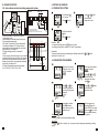
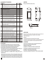
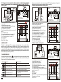
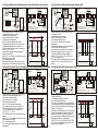
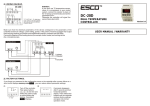
12. NOTES.
SC-20D
TEMPERATURE CONTROLLER
USER MANUAL / WARRANTY
12
Version 2.0
11.2. Domestic hot water circuit circulation pump and central heating circuit pump co
1. SPECIFICATIONS.
Input:
two temperature sensors: NTC 5k by 25°C
bistate input (normally opened or normally closed)
Measuring range::
-50...+150°C
Measuring accuracy:
±0,5%
Sampling period:
330 ms
Display resolutio:
0,1°C in whole range
Setting resolution:
0,1°C in whole range
Display:
LED, 4 digits, 11mm height with graphic icons
Control form:
ON-OFF with hysteresis
Protection class:
Ip20 / II
Power supply:
230V~ ±15% or 12V=/~, max 3VA
Operating conditions:
-5...60°C; 0...85%RH (non-condensing)
Storage conditions:
-40...85°C; 0...85%RH (non-condensing)
set
Boiler
T2
2. OUTPUTS CARRYING CAPACITY.
Output:
Relay:
Maximum resistive
load (for example heater):
Maximum inductive
load (for example engine):
OUTPUT1
30A 250V~
105 cycles
20A, 4500W
8A, 1500W, 2HP(2KM)
OUTPUT2
8A 250V~
105 cycles
8A, 1500W
2A, 400W, 0.5HP(0.5KM)
20(8)A
SC-20D
8(2)A
11 12 13 14 15 16
M
T2
T1
Pk
Pco
Pch
T1 - boiler temperature sensor
T2 - fireplace temperature sensor
Collector pump and c.h. pump max. 400W 230V~
Pdhw
Cold
water
Functions performed by the controller in the system:
- domestic hot water circulating pump and central heating
pump control system.
Tips for parameters programming:
F10=1 (container T1 and boiler T2 temp measurement)
F11=setting specifying the boiler temperature growth in
relation to the container temperature so that the domestic
hot water pump switches on, for example 8 °C
F12=DHW pump switching hysteresis, for example. 2°C
F15=given water temperature in the container. DHW pump
has a priority, so that only after reaching this setting, central
heating pump switches on, for example 60 °C
F16=OFF; F17=0.1; F21=0; F29=COOL ; F50=0 ; F51=0
F52=0 (when central heating pump switches on, domestic
hot water pump switches off)
Power supply
230V~
Temp.
T2-T1
10°C F11
8°C
6°C
F12=2°C
F12=2°C
Time
Main
output
1
Time
0
Auxiliary
output
when T1>F15
1
0
Time
3. FRONT PANEL.
temperature display
temperature sensor number
entry to the parameters menu
set
M
temperature setting button
value increasing button
value decreasing button
temperature setting signalling
OUTPUT1 signalling. LIGHTS: output active; BLINKS: output waits for start-up
OUTPUT2 signalling. LIGHTS: min or max temperature value exceeded (see: F15 or F16);
BLINKS: output waits for start-up (see: F17)
emergency states signalling
2
11
4. CONTROLLER HANDLING.
11. ADVANCED SYSTEMS.
11.1. Solar collector and boiler circulating pump control system.
4.1. TEMPERATURE SETTING.
20(8)A
SC-20
8(2)A
Push the button set
for 2 seconds.
°C
set
M
11 12 13 14 15 16
Pb
T2
T2
Pk
set
Pco
Diode
M
lights up.
Using
or
button
set the desired
temperature value.
°C
set
M
T1
Pc
Functions performed by the controller in the system:
–collector pump control
–central heating boiler circulating pump control system
Tips for parameters programming:
F10=1 (boiler T1 and collector T2 temp. measurement)
F11=temperature difference T2-T1 between the solar
collector and the boiler after reaching that, the collector's
pump switches on, for example 8 °C
F12=pump switching hysteresis, for example 2°C
F15=OFF
F16=In cloudy days, when solar energy is low, it is essential
to heat-up the boiler from the other source. This parameter
specifies the boiler temperature below which an external
heating source switches on, for example boiler circulating
pump. Setting, for example 40 °C.
F17=90min (external heating source switching delay)
F21=0; F29=COOL ; F50=0 ; F51=0 ; F52=0
T1 - boiler temperature sensor
T2 - fireplace temperature sensor
Collector pump and c.h. pump max. 400W 230V~
Power supply
230V~
Temp.
set
T2-T1
10°C
8°C F11
6°C
F12=2°C
F12=2°C
Time
Main
output
1
°C
Confirm the set with
set Key.
M
Diode
lights off.
Remarks:
–to cancel the setting, press the M button in any time
–the setting change can be limited by F13 and F14 parameters
Information:
To improve quick increasing or decreasing the settings values hold the
constantly for at least 1 sec.
button
Time
0
Auxiliary
output
4.2. PARAMETERS PROGRAMMING.
When T1<F16
1
0
Time
set
set
M
M
°C
set
M
Enter the menu holding
M Key for 5 sec., Until:
Command
displays.
Using
or
key
choose the parameter
you want to change and
enter with
set Key.
Using set key confirm
the new parameter
value and return to the
parameters list.
Remarks:
- press M button to cancel the parameter setting
Information:
Hold
or
values.
10
or
set
M
°C
set
set
If the access is protected
Command
displays.
Using
,
and set
Buttons enter the
password and confirm
with set key.
Using
or
button
set the desired
parameter value.
M
M
Finish programming
pressing M button or
enter the ‘’End’’ command
and press set key or wait
30 sec. without pressing
any button
button for at least 1 sec. to improve quick increasing and decreasing of setting
3
4.3. DESCRIPTION OF THE PARAMETERS.
8. MOUNTING.
Code: Description:
Range:
Default:
F10 Controller work mode:
0 - normal (displays from the main sensor T1, auxiliary sensor T2 off)
1
0, 1, 2
1 - differential (display difference between auxiliary and main sensor (T2-T1)
2 - average (display average from two sensors: main and auxiliary (T1+T2/2)
F11 Value of tempereture setting. Range of changes is limited by F14 and F13.
F14...F13
8.0°C
F12 Hysteresis (temperature control accuracy).
0.1...20.0°C
0.5°C
F13 Maximum value possible to set by the user.
-50.0...150.0°C 150.0°C
-50.0...150.0°C -50.0°C
F14 Minimum value possible to set by the user.
F15 High temperature alarm. F15=OFF – alarm off
-50.0...150.0°C
85°C
F16 Low temperature alarm. F16=OFF – alarm off
-50.0...150.0°C
5.0°C
F17 The delay of switching high and low temperature.
0.1...99.9min
0.1min
F18 Temperature sensor T2 calibration. This is the value of rescaling the T2
-20.0...+20.0°C
0.0°C
temperature sensor in relation to actually measured temperature.
F19 Temperature sensor T1 calibration. This is the value of rescaling the T1
-20.0...+20.0°C
0.0°C
temperature sensor in relation to actually measured temperature.
F21 Output1 minimum down time. It also means the delay time of switching
0.0min
0.0...10.0min
the output on after giving power supply. Parameter protects devices,
for example engine from too frequent switching in case of power failure.
F29 Controlling output work mode: COOLING/HEATING
COOL/HEAT
COOL
F50 Digital input D1: 0 – unused; 1 – alarm when circuit 4-5 closed,
2 – alarm when circuit 4-5 closed with maintaince of alarm signalling,
0...4
0
3 – alarm when circuit 4-5 opened,
4 – alarm when circuit 4-5 opened with maintance of alarm signalling
F51 Sound signaller (beep) active when temperature alarm: 0 – N0, 1 – YES
0, 1
1
F52 The way of protection the system and the devices connected to the main
output when the temperature alarm occurs: 0 – main output off and locked
0, 1, 2
0
when an alarm, 1 – main output on and locked when the alarm,
2 – alarm does not affect the operation of the main output
F57 Output2 contacts scheme: 0-contacts normally opened, closed when the
temperature alarm or when digital input activation; 1-contacts normally closed,
0, 1
0
opened when the temperature alarm or when digital input activation
F80 Password to access the configuration menu.
0000...9999
OFF
OFF – password protection inactive, F80 = 0000 – no password
F83 Display mode 0 - measurement from two sensors displayed alternately every
0, 1, 2
0
3 sec.; 1 - measurement from T1 sensor; 2 - measurement from T2 sensor
F98 Reserved.
F99 Controller test. Disconnect output device to make the test!
Otherwise the system can crash.
End Exit the menu.
Mounting on a DIN rail(TS35), 50cm width (3 modules).
5. GENERAL DESCRIPTION.
5.1. ADJUSTMENT.
10. ADM ISSIONS.
SC-20 is designed to control the heating and cooling system. A wide range of configuration
makes the controller perfect for use in typical arrangements, such as boiler or circulating pump
Control and complex, for example: solar collector or fireplace with water jacket control.
Adjustment is based on the measurement from one or two temperature sensors:
–when measuring from one sensor (F10=0) controller mainstains the set temperature switching on the
main output in ''heating'' or ''cooling'' mode with deviation (regulated hysteresis)
– when measuring from two sensors the user can select the operating mode of the controller:
–the output is activated based on the difference (F10=1) or average (F10=2) from two
temperature sensors.
In differential mode, the controller activates, e.g. Collector circulating pump after reaching an essential
difference between boiler's and collector's sensor. And in averaging mode, the controller operates as
an usual temperature controller except that the measured value is calculated from the arithmetic
average of readings from two temperature sensors, for example at the two ends of the pipeline or the
4boiler.
14
51
50 (3 mod.)
45
67,2
89,5
32
35
6
50
2000
20
Protection class
IP67
9. INSTALLATION.
Be aware of the conditions where the controller operates. Install in a place, where there is not
too high temperature and humidity and no condensation. Should be ventilated
in order to remove the heat.
ATTENTION!
It is not allowed to work with electric cables when the device is energized.
You should avoid crossing wires using short connections. We recommend securing the source
of controller power supply and temperature sensor input against electrical interference
Controller meets the requirements for immunity to electromagnetic interference in an
industrial environment according to the following standards:
Electromagnetic compatibility (EMC):
–EN-61000 part 6-4 – requirements for emissivity in an industrial environment
–EN-61000 part 6-2 – requirements for immunity in an industrial environment
It also meets the safety requirements according to standard:
–EN-61000 part 1 – safety requirements for eletrical devices
Controller meets the requirements of EU directives No. 72/23/EEC; 93/68/EEC; 89/336EEC.
9
5.7. Chamber, incubator and boiler with adjustment calculated from the arithmetic
mean of the measurements from two temperature sensors T1 and T1 PRECISE
control system.
20(8)A 8(2)A
SC-20
Here are some examples of control systems using the SC-20 including diagrams of supported
installations, tips for programming and diagrams of electric connections.
5.2. Heater with external alarm control system.
SC-20
Alarm
20(8)A
8(2)A
11 12 13 14 15 16
set
set
M
T2
BOILER
T1
~230V
Heater
T2
T1 - boiler temperature sensor
T2 - fireplace temperature sensor
Heater max. 3200W, Signaller 230V~
Temp.
Functions performed by the controller in the system:
–heater control
–external acoustic signaller control
–system protection against overheating and freezing
–emergency states sound signalling
Tips for parameters programming:
F10 = 2 (temperature measurement from two sensors T1
and T2)
F11 = temperature setting
F12 = heater switching hysteresis, for example 1 °C
F15 = high temperature alarm, for example 85 °C
F16 = low temperature alarm, for example 5 °C
F17 = 0.1; F21 = 0;
F29 = HEATING;
F50 = 0; F51 = 1; F52 =0
11 12 13 14 15 16
M
Alarm
Electr.
Heater
Thermostat
STB
Heater
Power supply
230V~
T1+T2
2
85°C
F15
81°C F11
80°C
79°C
F12=1°C
F12=1°C
5°C
F16 Time
Main
output
1
0
Auxiliary
output
Time
1
0
Time
Heater
Alarm
Alarm
T1 - main temperature sensor
D1 - external safety thermostat STB
Heater max. 3200W, signaller 230V~
T1
Functions performed by the controller in the system:
–heater control (boiler, electric heater, etc.)
–external acoustic signaller control
–system protection against overheating and freezing
–emergency states sound signalling
Tips for parameters programming:
F10 = 0 (system temp. measurement from T1 sensor)
F11 = temperature setting
F12 = heater switching hysteresis, for example 1 °C
F15 = high temperature alarm, for example 85 °C
F16 = low temperature alarm, for example 5 °C
F17 = 0.1; F21=0; F29=HEATING
F50 = 0 or 2 (2 – if you used the external safety thermostat
STB connected to the D1 input)
F51 = 1 (sound signaller active)
F52 = 0 (heater off in danger point)
Power supply
230V~
Temp.
85°C
F15
81°C F11
80°C
79°C
F12=1°C
F12=1°C
5°C
F16 Time
Main
output
1
Time
0
Auxiliary output
1
Time
0
5.3. Heater and fan control system.
6. DIGITAL INPUT.
Controller has digital input D1 for emergency states signalling, such as system failure,
pressure control or safety thermostat activation, etc. Input type (normally opened, normally
closed) is programmed by F50 parameter. After opening/closing circuit of 4-5 digital input, the
controller turns off the main output and turns on the sound signaller (beep) and an auxiliary output
and the display shows A11 code. Emergency state sound signalling can be maintained, until the
alarm reset by using the buttons (F50=2 or 4).
SC-20
set
Heater
T1
20(8)A
M
8(2)A
11 12 13 14 15 16
Termostat
STB
Fan
Grzałka
Wentylator
7. ALARM MESSAGES.
When alarm activates the indicator
starts to blink and the sound signaller (beep) activates
(when F83=1). According to the occurence controller turns on/off output and the front panel
displays one of the following alarm messages:
Statement
8
Occurence
digital input activation F50
Output operation
auxiliary output active, the main inactive
T1 sensor error:
open circuit or short circuit
auxiliary output active, the main inactive
T2 sensor error:
open circuit or short circuit
auxiliary output active, the main inactive
high temperature alarm F15
auxiliary output active, the main depends on
the setting of F52
low temperature alarm F16
auxiliary output active, the main depends on
the setting of F52
T1 - main temperature sensor
D1 - external safety thermostat STB
Heater max. 3200W, fan 400W 230V~
Functions performed by the controller in the system:
–heater heating up the chamber control
–fan cooling the chamber control
–emergency states sound signalling
Tips for parameters programming:
F10 = 0 (temperature measurement from T1 sensor)
F11 = temperature setting
F12 = heater switching hysteresis, for example 1 °C
F15 = temperature setting of switching the fan cooling the
chamber, for example 30 °C
F16 = OFF
F17 = 0.1; F21 = 0
F29 = HEATING
F50 = 0 or 2 (2 – if you used the external safety thermostat
STB connected to the D1 input)
F51 = 0; F52 = 0
Power supply
230V~
Temp.
30°C
F15
21°C F11
20°C
19°C
F12=1°C
F12=1°C
Time
Main
output
1
0
Auxiliary output
czas
1
0
Time
5.3. Central heating circuit circulating pump with an external alarm control system.
SC-20
Alarm
set
20(8)A
M
8(2)A
5.5. Solar collector with an external alarm control system .
SC-20
Alarm
11 12 13 14 15 16
T1
Central
heating
pump
Thermostat
STB
Boiler
Functions performed by the controller in the system:
–central heating circulating pump control
–external acoustic signaller control
–system protection against overheating
Tips for parameters programming:
F10=0 (T1 pipeline temperature measurement)
F11=pump start temperature setting, for example 40 °C
F12=pump switching hysteresis, for example 0.1 °C
F15=high temperature alarm in boiler, for example 85 °C
F16=OFF; F1 = 0.1; F21 = 0
F29=COOLING (switching pump after reaching the
temperature of the boiler)
F50=0 or 2 (2 – if you used an external safety thermostat
STB connected to the D1 input)
F51=1 (sound signaller active)
F52=0 (when the high temperature alarm occurs, the
pump switches on to cool down the water in the boiler)
Pch
Pc
T1
Cp
85°C
F15
40°C
F11±F12
Functions performed by the controller in the system:
–collector pump control
–external acoustic signaller control
–boiler protection against overheating
Tips for parameters programming:
F10=1 (boiler T1 and collector T2 temperature
measurement)
F11=temperature difference T2-T1 between the solar
collector and the boiler after reaching
that, the collector's pump switches on, for example 8 °C
F12=pump switching hysteresis, for example 2 °C
F15=boiler overheating alarm, for example 85 °C
F16=OFF; F17 = 0.1; F21 = 0, F29 = COOL; F50 = 0
F51=1 (sound signaller active)
F52=0 (when the boiler overheating alarm occurs, pump is
turned off so as not to collect a hot factor from the
collector)
Time
Main
output
1
Time
0
Auxiliary
output
1
Time
0
Alarm
T2
T1 - boiler temperature sensor
T2 - collector temperature sensor
Power supply
Collector pump Pk and signaller max. 400W 230V~
230V~
Power supply
230V~
Temp.
8(2)A
11 12 13 14 15 16
M
set
T2
Alarm
T1 - main temperature sensor
D1 - external temperature sensor STB
Pump Pch and signaller max. 400W 230V~
20(8)A
Temp
T2-T1
10°C F11
8°C
6°C
F12=2°C
F12=2°C
Time
Main
output
1
Time
0
Auxiliary
output
When T1>F15
1
Time
0
5.4. Domestic hot water circuit circulating pump with an external alarm control system. 5.6. Fireplace with water jacket control system.
SC-20
Alarm
set
20(8)A
M
8(2)A
11 12 13 14 15 16
set
FIREPLACE
Thermostat
STB
T1
Pdhw
20(8)A
SC-20
Alarm
8(2)A
11 12 13 14 15 16
M
T2
T1
T2
Pc
Pch
Pch
D.h.w. Pump
Cold water
Boiler
Functions performed by the controller in the system:
–domestic hot water circulating pump control
–external acoustic signaller control
–system protection from overheating
Tips for parameters programming:
F10 = 0 (T1 boiler temperature measurement)
F11 = boiler temperature setting, for example 60 °C
F12 = pump switching hysteresis, for example 0.1 °C
F15 = high temperature alarm, for example 85 °C
F16 = OFF; F17 = 0.1; F21 = 0
F29 = HEATING (pump works until the temperature is
reached)
F50 = 0 or 2 (2 – if you used an external safety thermostat
STB connected to the D1 input)
F51 = 1 (sound signaller active)
F52 = 1 (when high temperature alarm occurs, the pumps
is switched on)
T1 - main temperature sensor
D1 - external safety thermostat STB
Pompa Pdhw i signaller max. 400W 230V~
Pc
Power supply
230V~
Functions performed by the controller in the system:
- fireplace pump control
- central heating circulating pump control.
Tips for parameters programming:
F10=1 (boiler T1 and fireplace T2 temp. measurement)
F11=setting specifying the fireplace temperature growth in
relation to the boiler temperature so that the fireplace pump
switches on, for example 8 °C
F12=fireplace pump switching hysteresis, for example 2 °C
F15=set water temperature in the boiler. Loading the
domestic hot water boiler using the fireplace pump is a
priority, so that only after reaching this setting, the central
heating pump switches on, for example 60 °C
F16=OFF; F17=0.1; F21=0; F29=COOL; F50=0; F51=0
F52 = 0 (when the central heating pump switches on,
fireplace pump is switched off)
Temp.
85°C
F15
60°C
F11±F12
Time
Main
output
1
0
Auxiliary
output
Time
1
0
Cold
Water
Time
T1 - boiler temperature sensor
T2 - fireplace temperature sensor
Collector pump and c.h. pump max. 400W 230V~
Power supply
230V~
Temp.
T2-T1
10°C F11
8°C
6°C
F12=2°C
F12=2°C
Time
Main
output
1
Time
0
Auxiliary
output
When T1<F16
1
0
Time