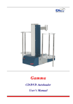
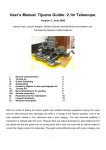
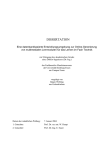
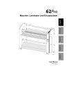
1
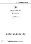
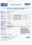
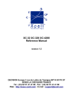
USER MANUAL
MAD DOG DRAG BRAKE
MADDOCK MACHINE LLC
VIDA, OREGON
Copyright © Maddock Machine2015 All rights reserved.
Reproduction of the contents of this manual, in any form or by any means, is prohibited without the written permission of the copyright owners.
1
-----TABLE OF CONTENTS-----
TABLE OF CONTENTS------------------------------------------------------------------------------------------------2
TABLE OF DRAWINGS------------------------------------------------------------------------------------------------2
ABOUT THIS MANUAL-----------------------------------------------------------------------------------------------2
TERMS & CONVENTIONS-------------------------------------------------------------------------------------------3
TABLE OF DRAWINGS------------------------------------------------------------------------------------------------2
-----ABOUT THIS MANUAL----This manual is divided into four main sections.
Section 1--------------------------------------------------------------------------------------------------------------4
This section describes:
The function of the brake.
The kit contents
Section 2----------------------------------------------------------------------------------------------------------------6
This section describes:
Tools and supplies needed
Installation of the Drum
Installation of the Outer Plate
Installation of the Hooker
Section 3------------------------------------------------------------------------------------------------------------------9
This section describes:
Drum removal
Section 4-------------------------------------------------------------------------------------------------------------------9
This section describes:
Daily checks
Maintenance
Suggestions for use
TABLE OF DRAWINGS
Drawing num. 1 parts shoe side----------------------------------------------------------------------------------10
Drawing num. 2 parts outside------------------------------------------------------------------------------------10
Drawing num. 3 Pacman to axle center distance--------------------------------------------------------------11
Drawing num. 4 Reaction Arm to Drum clearance------------------------------------------------------------11
Drawing num. 5 Reaction Arm & bolt head clearance with pacman---------------------------------------12
Drawing num. 6 Cable length measurement, hooker Screw placement, Cable cut-----------------------12
Drawing num. 7 Hooker Screw extension----------------------------------------------------------------------13
PARTS LIST-------------------------------------------------------------------------------------------------------------14
WARRANTY------------------------------------------------------------------------------------------------------------15
Copyright © Maddock Machine2015 All rights reserved.
Reproduction of the contents of this manual, in any form or by any means, is prohibited without the written permission of the copyright owners.
2
-----TERMS AND CONVENTIONS---------CAUTION----A CAUTION DENOTES AN ACTION THAT MAY POSE A RISK OF,
OR RESULT IN, DAMAGE TO EQUIPMENT
-----WARNING----A WARNING DESCRIBES ANY ACTION THAT MAY POTENTIALLY
RESULT IN INJURY OR DEATH
----SECTION 1--------DESCRIPTION----THE MAD DOG DRAG BRAKE AND THE MM 4.125 DRAG BRAKE (HENCEFORTH
REFERRD TO AS “THE BRAKE”) IS A SECONDARY BRAKE DESIGNED SPECIFICALLY
FOR THE USE OF HELPING TO CONTROL THE DOWNHILL SPEED OF A BICYCLE.
THE BRAKE IS NOT INTENDED FOR USE AS A STOPPING BRAKE AND MUST
NOT BE USED FOR THAT PURPOSE.
-----The Drum Brake Kit Contains----1- Drum- threaded 1.37x24 tpi ISO/bike.
2- Outer plate.
3- Shims, 1 each of 1mm & .5mm.
4- Operating cable hooker & hooker screw.
5- warranty card.
-----WARNING----Copyright © Maddock Machine2015 All rights reserved.
Reproduction of the contents of this manual, in any form or by any means, is prohibited without the written permission of the copyright owners.
3
THIS IS NOT A STOPPING BRAKE
----- WARNING ----IMPROPER USE OF THE MDD or MM4.125
MAY RESULT IN SEVERE INJURY OR DEATH
-----EQUIPPING YOUR BIKE TO USE THE DRUM BRAKE----Your bike must be properly equipped to mount and use the drum brake.
1- The rear hub must be threaded 1.37 X 24 tpi ISO/bike on the non drive side.
2- The left chain stay must have a fitting to restrain the reaction
arm. This fitting is sometimes called a pacman. The distance from
center of the axle to the rear of the pacman opening must not be
greater than 4 .46”(113.28mm) or less than 4.42” (112.27mm).
See drawing num.3
3- A device to operate the drum brake.
------ WARNING ----NEVER USE A SINGLE HAND LEVER TO OPERATE THE DRUM BRAKE AND THE
REAR CALIPER BRAKE TOGETHER. THE USE OF A SINGLE HAND LEVER IN THIS
MANNER CAN LEAD TO UNPREDICTABLE AND UNCONTROLLABLE SKIDDING OF THE
REAR WHEEL, LOSS OF CONTROL OF THE BIKE, SEVERE INJURY, EVEN DEATH.
The most common operators are:
A- A third brake lever.
B- A friction shift lever.
C- A bar end shift lever.
D- An equalizer may be used to operate both front and rear caliper
brakes with one brake lever, and the second lever used to operate
the drum brake.
The operator may be mounted at the captain or stoker position.
----SECTION 2---Copyright © Maddock Machine2015 All rights reserved.
Reproduction of the contents of this manual, in any form or by any means, is prohibited without the written permission of the copyright owners.
4
IF YOU ARE NOT FAMILIAR WITH THE TOOLS OR
PROCEDURES DESCRIBED IN THIS MANUAL
CONSULT WITH YOUR DEALER
----- INSTALLING THE DRUM BRAKE ----Things you will need:
1- Cleaning Equipment
A. A toothbrush or other small fine bristle brush.
B. Solvent or cleaning solution.
C. Rags or paper towels.
2- Tools
A. 2 mm hex wrench.
B. Cable cutter.
C. Inch Lb. rated torque wrench with 2mm hex drive bit.
3- Supplies
A. Anti-seize or high temperature grease.
-----
INSTALLATION OF THE DRUM-----
1- Remove rear wheel.
2- Remove QD (quick release) skewer.
3- Remove existing brake if applicable.
4- Remove non-drive side serrated washer and spacer.
5- Remove thread protector if present.
6- Clean hub and drum threads with solvent and brush.
7- Dry threads.
8- Examine threads. Threads must be free from damage, dings, dents, or any disruptions
of the threads If any damage is found, DO NOT PROCEED WITH INSTALLATION,
CONSULT YOUR DEALER.
9- Lightly coat threads with anti-seize or high temp grease.
10- Thread drum onto hub. It is critical that extreme caution be used
when starting the threading.
-----CAUTION----Cross threading can damage the hub and the drum. If you experience
any difficulty in starting the thread or binding in threading the drum
up to the shoulder, STOP, carefully remove drum. Re-clean threads and
examine. See step #8 above.
11- Thread drum on until it stops at the shoulder of the hub. DO NOT TIGHTEN. Somewhat loose
is good at this point as the drum will tighten with use.
12- Clean up any anti-seize or grease left inside the drum and the drum/hub shoulder.
Copyright © Maddock Machine2015 All rights reserved.
Reproduction of the contents of this manual, in any form or by any means, is prohibited without the written permission of the copyright owners.
5
----- INSTALLATION OF OUTER PLATE----The outer plate is supplied with a bushing allowing the brake to be
installed on hubs with either a 10mm or 12mm axle. If your hub is
equipped with a 10mm axle use the outer plate as supplied. For use with
12mm axles the bushing must be removed. The best method of removal of
the bushing is with the MDD bushing removal tool available from your
dealer. If you must remove the bushing without the bushing tool,
-----CAUTION----BE VERY CARFULL NOT TO DISTORT THE OUTER PLATE.
A small punch with a flat tip may be used to remove the bushing. Support
the outside of the outer plate on a hardwood block centered over a hole
slightly larger than 12mm,with the small punch contacting ONLY the bushing,
gently tap the bushing out with a small hammer.
1- Place outer plate on axle and push all the way on.
2- Check for clearance between the inside of the reaction arm and the
outer lip of the drum. There must be no less than 1mm of clearance.
There are two shims supplied with the drum brake. One each of 1mm and
.5mm. Remove outer plate, Use one or both to obtain proper clearance.
Re instal outer plate. See drawing num. 4
3- Install the serrated washer.
4- Check the above clearance again.
5- Temporarily install wheel into dropouts WITHOUT the reaction arm
engaging the pacman, tighten QR to your normal setting, CHECK CLEARANCE
AGAIN.
----- CAUTION----Failure to allow for proper clearance between the drum and
reaction arm will damage the drum and void warranty.
6- Remove and reinstall wheel with reaction arm anchor bolt engaged into
the pacman. The outer plate MUST NOT be pushed out of alignment by the
reaction arm or the anchor bolt head touching the side of the pacman.
If the arm or bolt head is touching the pacman, remove wheel and
VERY GENTLY slightly bend the arm so that only the barrel of the bolt
touches the pacman. Reinstall wheel and check arm/bolt head/pacman
clearance, adjust as necessary. See drawing num. 5
-----WARNING---DO NOT USE A LONGER BOLT TO ADJUST THE CLEARANCE
7- Check the for and aft position of the anchor bolt barrel in pacman slot.
The anchor bolt barrel must be close to rear end of the slot but not
touching it. If the anchor bolt is not in the above position STOP the installation.
8- Engage brake manualy and turn wheel counterclockwise to tighten deum onto the
hub. This will tend to centralize the drum to the hub.
Copyright © Maddock Machine2015 All rights reserved.
Reproduction of the contents of this manual, in any form or by any means, is prohibited without the written permission of the copyright owners.
6
----- WARNING ----STOP DO NOT PROCEDE WITH INSTALLATION,
REMOVE THE BRAKE,
DO NOT USE THE BRAKE.
THE PACMAN IS IN THE WRONG POSITION
FOR USE WITH THIS BRAKE. DAMAGE
TO YOUR FRAME MAY OCCURE,
CONTACT YOUR DEALER.
-----INSTALLATION OF THE CABLE HOOKER----1- Install operator and cable at desired position.
2- Route cable to left chain stay.
3- Remove hooker screw from hooker.
4- With a 2mm hex wrench, back out set screws so that the cable
passes through the axial hole of the hooker screw.
5- thread cable through axial hole of the hooker screw.
6- place hooker on actuating arm.
7- push actuating arm forward until resistance is felt.
8- Hold hooker hooker screw parallel to the hooker so that the faces touch.
See drawing num. 6
9- With a 2mm hex wrench snug up the two set screws.
10- Cut cable at right hand end of the hooker screw.
See drawing num. 6
11- Tighten set screws 10 to 12 Inch Lb. (1.1 to 1.4 NM) with torque wrench.
12- Install hooker screw into hooker, thread together until there is about
1/16” to 1/8” (1.6mm to 3.2mm ) between the faces.
13- Push Actuation Arm forward, engage hooker pin
into Actuation Arm slot. Be sure the hooker pin drops to bottom
of the hooker slot. The brake should not be engaged at this setting.
If brake is engaged unscrew hooker screw until brake is not engaged.
-----WARNING---THE MAXIMUM SPACE ALLOWED BETWEEN THE HOOKER
SCREW FACE AND THE HOOKER FACE IS 15/64” (5.95mm)
UNDER NO CIRCUMSTANCE MAY THIS SPACING BE
EXCEEDED. SEE DRAWING NUM. 7
14- TEST THE BRAKE ON LEVEL GROUND BEFORE USING
IN HILLY TERRAIN.
Copyright © Maddock Machine2015 All rights reserved.
Reproduction of the contents of this manual, in any form or by any means, is prohibited without the written permission of the copyright owners.
7
----SECTION 3----
-----DRUM REMOVAL---------CAUTION----USE ONLY APPROVED TOOLS FOR DRUM REMOVAL
USE OF OTHER TOOLS OR METHODS MAY DAMAGE
DRUM AND VOID WARRANTY
APPROVED TOOLS FOR DRUM REMOVAL:
1- MMDB-00037 special wrench for use in conjunction with a 1/2”
ratchet wrench or breaker bar. Available from your dealer.
2- 1 5/8” or 41mm Socket.
----- INSTRUCTIONS FOR DRUM REMOVAL----1- Remove rear wheel from bike
2- Remove outer plate
3- Apply special wrench or socket to central hex of the drum , unscrew counter clockwise.
-----WARNING----DO NOT TOUCH BRAKE WITH BARE SKIN
AFTER USE. IT WILL BURN YOU. ALLOW BR AKE
TO COOL BEFORE TOUCHING IT.
----SECTION 4--------DAILY CHECKS ----1- Prior to use you should visually check the brake to ensure that it appears to be in working order.
2- Operate the brake before starting your ride to ensure that the brake seems mechanically sound.
3- On level ground , before you get to hills on which you will want to use the brake, actuate the brake
gently as a test of smooth operation.
4- After using the brake in wet weather, be very careful applying the brake until you are sure that the
brake operates smoothly. The braking surface of the drum can develop rust which can effect the
smooth operation of the brake. If you encounter this problem, repeated gentle operation of the brake
will smooth it out, if this does not smooth out operation of the brake see #2 in maintenance section.
Copyright © Maddock Machine2015 All rights reserved.
Reproduction of the contents of this manual, in any form or by any means, is prohibited without the written permission of the copyright owners.
8
-----MAINTAINCE----1- Always perform the daily checks.
2- After a lengthy period of storage the outer plate should be removed to check the condition of the
braking surface of the drum and the braking surface of the shoes. If the braking surface of the
drum shows any sign of rust, lightly sand the surface with 150 grit sand paper. If the shoes appear
to have a glazed surface, lightly sand the surface with 150 grit sand paper to remove the glazing.
-----SUGESTIONS FOR USE----1- When approaching a steep or long descent, moderate your speed.
2- Actuate drum brake before you get to white knuckle speed.
3- When descending a long hill, pulse the brake to allow it to cool.
-----WARNING----4- Be very careful when using the rear caliper brake and the drum brake together.
The combination of the two may cause skidding of the rear wheel leading to loss
of control. It is best to release the drum prior to engagement of the rear caliper
brake.
5- Give control of the brake to the stoker, they are way smarter than you and will most likely
save your life.
Thanks for purchasing the brake.
Tom Maddock
Maddock Machine
Vida, OR 97488
541.896.3843
Copyright © Maddock Machine2015 All rights reserved.
Reproduction of the contents of this manual, in any form or by any means, is prohibited without the written permission of the copyright owners.
9
-----PARTS----Drawing num. 1
Drawing num. 2
Copyright © Maddock Machine2015 All rights reserved.
Reproduction of the contents of this manual, in any form or by any means, is prohibited without the written permission of the copyright owners.
10
Drawing num. 3
Pacman to axle center distance
MINIUM
4.42"
(112.27mm)
AXEL CENTER
Pacman
MAXIMUM
4.46"
(113.28mm)
`
Drawing num. 4
Reaction Arm to Drum clearance
Reaction Arm
Minium 1mm
here
Drum
Copyright © Maddock Machine2015 All rights reserved.
Reproduction of the contents of this manual, in any form or by any means, is prohibited without the written permission of the copyright owners.
11
Drawing num. 5
Reaction Arm & Bolt head
clearance with Pacman.
Reaction Arm
Bolt head
clearance here
Copyright © Maddock Machine2015 All rights reserved.
Reproduction of the contents of this manual, in any form or by any means, is prohibited without the written permission of the copyright owners.
12
Drawing num. 7
Hooker Screw
extention
0.23 [5.94]
Maximum extention
DO NOT EXCEDE
THIS LENTH
Copyright © Maddock Machine2015 All rights reserved.
Reproduction of the contents of this manual, in any form or by any means, is prohibited without the written permission of the copyright owners.
13
-----PARTS LIST----from drawings num. 1 & 2 page 10
NUMBER FROM DRAWING
MADDOCK MACHINE PART NUMBER
1-Shoe stop--------------------------------------------------------------------------------MMDB-00370
2-Spring------------------------------------------------------------------------------------MMDB-00190
3-Outer Plate-------------------------------------------------------------------------------MMDB-00030
4-Shoe---------------------------------------------------------------------------------------MMDB-00200
5-10mm/12mm Bushing------------------------------------------------------------------MMDB-00320
6-Reaction Arm Bushing Screw---------------------------------------------------------MMDB-00060
7-Reaction Arm----------------------------------------------------------------------------MMDB-00040
8-Reaction Arm Anchor Bolt Nut-------------------------------------------------------MMDB-00260
9-Cam Pad----------------------------------------------------------------------------------MMDB-00220
10-Cam Bushing Screw-------------------------------------------------------------------MMDB-00300
11-Cam--------------------------------------------------------------------------------------MMDB-00080
12-Cam Bushing Nut---------------------------------------------------------------------MMDB-00120
13-Actuation Arm--------------------------------------------------------------------------MMDB-00130
14-Reaction Arm Anchor Bolt-----------------------------------------------------------MMDB-00250
15-Actuation Arm Washer----------------------------------------------------------------MMDB-00330
16-Actuation Arm Screw-----------------------------------------------------------------MMDB-00140
17-Reaction Arm Bushing-----------------------------------------------------------------MMDB-00050
18-Shoe Stop Screw------------------------------------------------------------------------MMDB-00280
19-Shoe Stop Washer-----------------------------------------------------------------------MMDB-00290
20-Hooker Pin-------------------------------------------------------------------------------MMDB-00310
21-Hooker------------------------------------------------------------------------------------MMDB-00160
22-Hooker Screw Set Screw---------------------------------------------------------------MMDB-00350
23-Hooker Screw----------------------------------------------------------------------------MMDB-00170
Not picturedDrum----------------------------------------------------------------------------------------MMDB-00010
Special Wrench-----------------------------------------------------------------------------MMDB-00037
Copyright © Maddock Machine2015 All rights reserved.
Reproduction of the contents of this manual, in any form or by any means, is prohibited without the written permission of the copyright owners.
14
----WARRANTY---PRODUCT MUST BE REGISTERED WITH MANUFACTURER WITHIN THIRTY (30)
DAYS OF PURCHASE.
THE MAD DOG DRAG BRAKE AND THE MM 3.125 DRAG BRAKE (“BRAKE”) ARE
WARRANTED TO THE ORIGINAL REGISTERED OWNER AGAINST DEFECTS IN
MATERIAL AND WORKMANSHIP FOR THE LIFE OF THE BRAKE.
THIS WARRANTY AGAINST DEFECTS IN MATERIALS AND WORKMANSHIP IS
LIMITED TO, AT THE COMPANY’S OPTION, THE REPLACEMENT OR REPAIR OF
ANY DEFECTIVE PARTS OR MATERIALS.
THIS WARRANTY TO REPLACE OR REPAIR IS CONDITIONED ON THE FOLLOWING:
1. Registration of the product with Manufacturer within thirty (30) days of purchase;
2. Reasonable opportunity by the Manufacturer to inspect for defects;
3. The Brake having not been subjected to misuse,negligence, or accident; and
4. The Brake having not been altered or modified.
EXCLUSION OF WARRANTIES
WARRANTIES OF MERCHANTABILITY OR OF FITNESS FOR A PARTICULAR
PURPOSE OR ARISING FROM A COURSE OF DEALING OR USAGE OF TRADE
ARE SPECIFICALLY EXCLUDED, AND THERE ARE NO WARRANTIES, EXPRESS
OR IMPLIED, WHICH EXTEND BEYOND THE DESCRIPTION OF THE PRODUCT
CONTAINED IN THIS MANUAL.
THE WARRANTY SHALL BE LIMITED TO THE REFUND OF THE PURCHASE
PRICE FOR THE PRODUCT.
THE MANUFACTURER SHALL NOT BE LIABLE FOR PROXIMATE, INCIDENTAL,
CONSEQUENTIAL, OR OTHER DAMAGES. MANUFACTURER’S LIABILITY SHALL
BE LIMITED SOLELY AND EXCLUSIVELY TO A REFUND OF THE PURCHASE
PRICE.
Copyright © Maddock Machine2015 All rights reserved.
Reproduction of the contents of this manual, in any form or by any means, is prohibited without the written permission of the copyright owners.
15