1
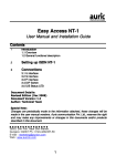
9. WIRING DIAGRAM.
1
3
2
4
5
T1 - temperature sensor
D1 - digital input
ES-10D
TEMPERATURE CONTROLLER
11 12 13 14 15 16
OUT1
Make sure that the electrical parameters of the device correspond to the parameters of the
controller (maximum voltage and current rating).
Connection diagram of the heating device (for example boiler, heater) or cooling device
(fan, circulation pump):
Heating or cooling
device
N
L
ES-10
20(8)A 250VAC
11 12
13 14 15 16
L
N
L
L
230VAC
N
10. ADMISSIONS.
Controller meets the requirements for immunity to electromagnetic interference in an
industrial environment according to the following standards:
Electromagnetic compatibility (EMC):
–EN-61000 part 6-4 – requirements for emissivity in an industrial environment
–EN-61000 part 6-2 – requirements for immunity in an industrial environment
It also meets the safety requirements according to standard:
–EN-61000 part 1 – safety requirements for eletrical devices
Controller meets the requirements of EU directives No. 72/23/EEC; 93/68/EEC; 89/336EEC.
USER MANUAL / WARRANTY
Version 3.0
5.4. DEFROSTING (for cooling applications).
1. SPECIFICATIONS.
Input:
Temperature sensor: NTC 5k by 25°C
bistate input (normally opened or normally closed)
Measuring range:
-50...+150°C
Measuring accuracy:
±0,5%
Sampling period:
330 ms
Display resolution:
0,1°C in whole range
Defrosting cycle is performed by the stoppage of the compressor. Cycles control is performed
automatically and run:
- periodically, from time to time (F35=1)
- according to the total compressor run time (F35=2). (The lower load of the cooling system, the
less often defrosting cycles occur).
The end of the defrosting cycle comes after passing F33 time. .
In difficult working conditions, if there is a need of an additional evaporar defrosting,
Process can be started manually pressing
button for 5 sec. “Defrosting” diode blinks
during the manual defrosting cycle.
Setting resolution:
0,1°C in whole range
6. ALARM MESSAGES.
Display:
LED, 4 digits, 11mm height with graphic icons
Control form:
ON-OFF with hysteresis
Protection class:
Ip20 / II
When alarm activates the indicator
starts blinking and the sound signaller (beep) will be
activated (when F83=1). According to the occurence controller turns on/off output and the front
panel displays one of the following alarm messages:
Power supply:
230V~ ±15% lub 12V=/~, max 3VA
Operation conditions:
-5...60°C; 0...85%RH (non-condensing)
Storage conditions:
-40...85°C; 0...85%RH (non-condensing)
Statement
2. OBCIĄŻALNOŚĆ WYJŚĆ
Occurence
Bistate input activation
Control output operation
Output inactive
Chamber sensor error:
OPE - open circuit
SHr - short circuit
High temperature alarm
Output inactive
Low temperature alarm
No influence
No influence
7. INSTALLATION.
Output:
Relay:
30A 250V~
105 cykli
Maximum resistive charge
(e.g. Heater):
Maximum inductive charge
(e.g. Engine):
20A, 4500W
8A, 1500W, 2HP(2KM)
3. FRONT PANEL.
Be aware of the conditions where the controller operates. Install in a place, where there is not
too high temperature and humidity and no condensation. Should be ventilated
in order to remove the heat.
ATTENTION!
It is not allowed to work with electric cables when the device is energized.
You should avoid crossing wires using short connections. We recommend securing the source
of controller power supply and temperature sensor input against electrical interference
8. MOUNTING.
temperature display
Mounting on a DIN rail (TS35), 50 cm width (3 modules).
temperature unit indicator
°C
M
entry to the parameters menu
set
temperature setting button
14
51
50 (3 mod.)
32
value increasing button
45
67,2
89,5
value decreasing button
pressing for more than 5 sec. forces defrosting cycle
temperature setting signalling
cooling output signalling. LIGHTS: output active; BLINKS: output waits for start-up (see: F21)
heating output signalling. LIGHTS: output active; BLINKS: output waits for start-up (see: F21)
35
defrosting signalling. LIGHTS: automatic defrosting mode; BLINKS: manual defrosting
emergency states signalling. BLINKS: alarm active
6
50
2
Protection class
IP67
2000
20
6
5. GENERAL DESCRIPTION.
4. CONTROLLER HANDLING.
5.1. ADJUSTMENT.
4.1. TEMPERATURE SETTING.
Controller is used to maintain T temperature with desired hysteresis T in cooling or heating
devices. Actuator control is in progress by the relay output and the temperature measurement is
made by the temperature sensor.
The principle of operation of the temperature control when cooling and heating:
Temp.
COOLING
Temp.
M
°C
set
HEATING
Press set button
for 2 seconds
Diode
Using:
°C
lights up.
M
or
set the desired
temperature.
set
91°C
6°C
T=1°C
T=5°C
T=1°C
4°C
T=1°C
T=90°C
T=1°C
Time
Output
M
°C
89°C
Time
set
Output
1
1
0
Time
0
Time
5.2. TEMPERATURE ALARM.
You can set upper and lower alarm threshold in controller parameters (F15 and F16
parameters), after exceeding which the high or low temperature alarm turns on.
Confirm the set with set
Button.
Diode
goes off.
Remarks:
– press M button in any time to cancel the setting
– the setting change can be limited by F13 and F14 parameters
Information:
To improve quick increasing or decreasing the settings values hold the
constantly for at least 1 sec.
or
button
Temp.
F15= 30°C
F16= -10°C
4.2. TEMPERATURE SETTING, when the SMART function is active (parameter F84=1)
High temperature alarm
Smart function allows for rapid temperature change with no need of pushing the SET button.
It is a very useful function for users, who often change temperatures.
Low temperature alarm
Time
Alarm
Switching delay F17= 0.1min
°C
1
0
Set the temperature by
or
pointer in any time. Diode
after 2 sec., and the controller saves the new setting.
goes off
Time
set
The alarm is turned on after the delay time (F17 parameter). Recommended time setting is 15
minutes, so that the alarm does not turn on too often in case of rapid temperature jumps.
The delay can be reduced to the minimum, i.e. 6 seconds (0,1min.), if the temperature does not
change abruptly. The alarm is signalled by internal buzzer or commands on the display:
- high temperature alarm
- low temperature alarm
Buzzer can be muted by pushing any button lub turned off permanently in F83 parameter.
M
Remarks:
–press M in any time to cancel the setting
–the setting change can be limited by F13 and F14 parameters
Information:
To improve quick increasing or decreasing settings values hold
at least 1 sec.
or
button constantly for
5.3. DIGITAL INPUT.
Controller has digital input D1 for emergency states signalling, for example system failure,
pressure control or safety thermostat activation, etc. Input type (normally opened, normally closed)
is programmed by F50 parameter. After input activation, the controller turns off the outputs, turns
on the beeper and the display indicates AL.d1. code. Emergency state sound signalling can be
maintained, until the alarm reset by using the buttons (F50=2 or 4).
5
3
4.3. PARAMETERS PROGRAMMING.
set
set
M
Enter the menu pressing
M button for 5 sec., Until
command
displays.
M
Using
or
button
choose the parameter
you want to change and
enter with set key.
°C
set
M
Using set key confirm
the new parameter
value and return to the
parameter list.
4.3. DESCRIPTION OF THE PARAMETERS.
set
M
°C
set
set
If the access to the menu
is protected,
command displays.
Using
,
and set
buttons enter the
password and confirm
with set
Remarks:
- press M button to cancel the parameter setting
Information:
Hold
or
values.
button for at least 1 sec. to improve quick increasing and decreasing of setting
Using
or
button
set the desired
parameter value.
M
M
Finish programming
pressing M button or
enter the “End” command
and press the set key
or wait 30 sec. without
pressing any button.
Others:
D1
input:
Cooling
applcations:
Output:
Adjustment:
Group: Code: Description:
F11 Temperature setting value. Range of changes is limited by the F14 and F13 parameters.
F12 Hysteresis (temperature control accuracy).
F13 Maximum temperature value possible to set by the user.
F14 Minimum temperature value possible to set by the user.
F15 High temperature alarm. F15=OFF – alarm off
F16 Low temperature alarm. F16=OFF – alarm off
F17 High and low temperature switching delay..
F19 Temperature sensor calibration. This is the value of rescaling the temperature sensor in relation to actually measured temperature.
F21 Main output minimal down time. It also means the delay time of switching the output on after giving power supply.
Parameter protects devices, e.g. engine against too frequent switching in case of power failure.
The recommended setting is 3 minutes in cooling system with compressor.
F29 Control output work mode: COOLING/HEATING
F31 - F37 parameters for cooling applications:
F31 Interval between defrosting cycles.
F33 Maximum defrosting cycle length.
F34 Dripping time of the evaporator after defrosting cycle. It is also the delay time of switching the compressor on after defrosting.
F35 Defrosting cycles control method. OFF - defrosting off , 1 - automatically, from time to time equals to F31,
2 - automatically, if the total time of compressor operation reaches the value equal to F31
F37 Compressor turned on during the defrosting cycle: 0 - NO, 1 - YES
F50 Digital input D1: 0 - unused; 1 - alarm when short-circuit; 2 - alarm when short-circuit with maintaince of alarm signalling;
3 - alarm when opened; 4 - alarm when opened with maintance of alarm signalling
F80 Password to access the configuration menu. OFF - password protection inactive. F80 = 0000 - no password
F82 Display resolution: 0=0,1°C; 1=1°C
F83 Sound signalling when an alarm: 0 - buzzer muted; 1 - buzzer active
F84 SMART function: 0 - active; 1 - inactive
You can change temperature quickly using the pointers.
F98 Reserved.
F99 Controller test. Disconnect output device to make the test! Otherwise the system can crash
End Exit the menu.
4
Range:
F14...F13
0.1...20.0
-50.0...150.0
-50.0...150.0
-50.0...150.0
-50.0...150.0
0.1...99.9
-20.0...+20.0
Default:
0.0
1.0
150.0
-50.0
OFF
OFF
15
0.0
Units:
°C
°C
°C
°C
°C
°C
Minutes
°C
0.0...10.0
0.0
Minutes
COOL/HEAT
HEAT
-
0.1...99.9
1...99
0...99
12.0
30
5
Hours
Minutes
Minutes
OFF,1, 2
OFF
-
0, 1
0
-
0...4
0
-
0000...9999
0, 1
0, 1
OFF
0
1
-
0, 1
0
-
-
-
-