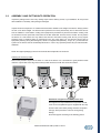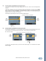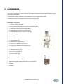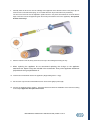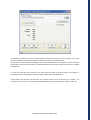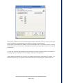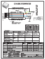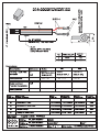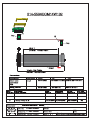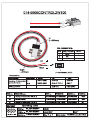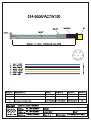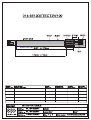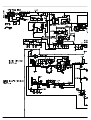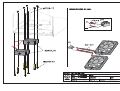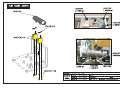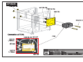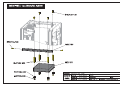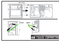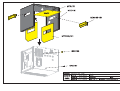
1
BTL-5000 SWT Series SERVICE USER GUIDE 101PL01/12/2008EN CONTENT 1 USER'S MANUAL..................................................................................................................................3 2 THERAPEUTIC ENCYCLOPAEDIA....................................................................................................50 3 SERVICE MENU MANUAL..................................................................................................................65 4 TROUBLE-SHOOTING........................................................................................................................86 5 PROCESS OF UPLOAD OF APPLICATIONS FROM PC BY SERIAL LINE - FOR END USERS .............................................................................................................................89 6 PROCESS OF UPLOAD OF APPLICATIONS FROM PC BY SERIAL LINE - FOR SERVICE...................................................................................................................................94 7 PROCESS OF UPLOAD OF APPLICATION IN THE SWT COMPRESSOR UNIT FROM PC BY SERIAL LINE - FOR SERVICE.........................................................................................................100 8 OUTPUT CONTROL..........................................................................................................................106 9 BLOCK DIAGRAM.............................................................................................................................110 10 CABLES.............................................................................................................................................113 11 LIST OF COMPONENTS...................................................................................................................127 12 ELECTRICAL SHEETS AND DRAWINGS........................................................................................130 13 ASSEMBLY DRAWINGS...................................................................................................................137 BTL-5000 Shockwave Series USER‘S MANUAL PAGE 1 OF 47 101IE30/07/2008EN BEFORE YOU START Thank you for showing your interest and buying our device the BTL- 5000 SWT Series. We hope you will be satisfied and thanks to you, this device will help many patients. All of us at BTL wish you every success with your BTL- 5000 SWT Series. We pride ourselves on being as responsive as possible to our customers’ needs. Your suggestions and comments are always welcome since we believe an ongoing relationship with our customers is critically important to our future product line. Please call or email us your suggestions. While we would like you to start using your equipment right away, we encourage you to thoroughly read this manual in order to fully understand the operational features of the BTL-5000 SWT system. Again, thank you for being a BTL customer. In the event of any problem, or if you require service, please make an initial call to your local distributor, who will decide whether to refer the problem to our office. PAGE 2 OF 47 CONTENTS 1 GENERAL CHARACTERISTICS OF THE DEVICE....................................................................................... 5 1.1 BTL – 5000 SWT System Series .................................................................................................................. 6 1.2 Shockwave and Its Character....................................................................................................................... 6 1.3 Shockwave Generation................................................................................................................................. 7 1.3.1 Ballistic Principle of the Shockwave Generation ......................................................................................7 1.4 Biological Effects of the Shockwave ............................................................................................................. 7 1.5 Advantages of the Shockwave Treatment .................................................................................................... 8 1.6 Possible Side Effects After the Shockwave Treatment ................................................................................. 8 1.7 Indications for the Shockwave Treatment..................................................................................................... 8 1.8 Contraindications to the Shockwave Treatment ........................................................................................... 9 2 INSTRUCTIONS FOR USE .......................................................................................................................... 10 2.1 Front Panel of the BTL- 5000 SWT............................................................................................................. 10 2.2 Rear Panel of the BTL- 5000 SWT ............................................................................................................. 11 2.3 Assembly and Putting into Operation.......................................................................................................... 12 2.4 OPERATING THE DEVICE ........................................................................................................................ 14 2.4.1 2.4.2 2.5 Touch Screen .........................................................................................................................................14 Numeric Keypad.....................................................................................................................................15 Therapy (Setting Principle) ......................................................................................................................... 16 2.5.1 2.5.2 2.5.3 2.5.4 Diagram of the Therapy Setting Process................................................................................................16 Welcome Screen and Selection of Channels, Tabs and Accessories ....................................................17 Setting Therapy Parameters Via the ‘diag’ Button..................................................................................18 Setting Therapy Parameters Via the 'prog' Button .................................................................................18 2.5.5 2.5.6 2.5.7 2.5.8 Setting Therapy Parameters Manually (User Setup) Via the ‘man' Button .............................................19 Therapy Parameters Screen – Ergonomic, Standard and Expert Mode.................................................20 Setting Number of Shocks......................................................................................................................20 Setting Therapy Intensity........................................................................................................................20 2.6 2.6.1 2.6.2 Course of Therapy ...................................................................................................................................... 20 Start - Interruption - End of Therapy.......................................................................................................20 Running Therapy Screen .......................................................................................................................22 2.7 Therapy Parameters ................................................................................................................................... 22 2.8 Encyclopaedia ............................................................................................................................................ 22 2.9 Therapy Saving .......................................................................................................................................... 23 2.9.1 2.9.2 3 3.1 3.1.1 3.1.2 Save Therapy and Add It to the Client Data ...........................................................................................24 End of Therapy / Shock Generation .......................................................................................................25 DEVICE MENU............................................................................................................................................. 26 Accessories ................................................................................................................................................ 26 Installation of Accessories......................................................................................................................26 Information about Accessories ...............................................................................................................26 PAGE 3 OF 47 3.1.3 Information about Connectors ................................................................................................................26 3.2 Unit Settings ............................................................................................................................................... 27 3.2.1 Password Setting ...................................................................................................................................27 3.2.2 3.2.3 3.2.4 3.2.5 3.2.6 Sound Setting.........................................................................................................................................27 Screen Saver and Auto Switch-Off.........................................................................................................28 Colour Setting ........................................................................................................................................28 Setting of Display Contrast.....................................................................................................................28 Date and Time Setting............................................................................................................................28 3.2.7 3.2.8 3.2.9 3.2.10 Language Setting ...................................................................................................................................28 Operation Mode......................................................................................................................................28 Touch Panel Calibration .........................................................................................................................28 User Options ..........................................................................................................................................28 3.2.11 3.2.12 3.2.13 3.2.14 3.2.15 Style of Operation...................................................................................................................................29 Setting of HW Key ..................................................................................................................................29 Unit Information ......................................................................................................................................29 Unlock Code...........................................................................................................................................29 Service Functions...................................................................................................................................29 3.3 3.3.1 3.3.2 4 Specific Settings ......................................................................................................................................... 30 Shockwave Setting.................................................................................................................................30 Applicator Kit Replacement Wizard ........................................................................................................31 USER OPTIONS........................................................................................................................................... 32 4.1 Clients......................................................................................................................................................... 32 4.2 User Sequences ......................................................................................................................................... 32 4.3 User Diagnoses/Programs.......................................................................................................................... 33 4.4 List of Recent Therapies............................................................................................................................. 33 5 APPLICATION OF SHOCKWAVES............................................................................................................. 34 6 ACCESSORIES............................................................................................................................................ 36 7 MAINTENANCE AND SAFETY INSTRUCTIONS........................................................................................ 37 7.1.1 Shock Transmitter Replacement Procedure...........................................................................................38 7.1.2 Procedure of Worn-out Tube and Projectile Replacement .....................................................................39 7.2 Safety of the Device.................................................................................................................................... 42 7.3 Warranty Conditions ................................................................................................................................... 43 8 TECHNICAL PARAMETERS ....................................................................................................................... 44 8.1 Applicable Standards.................................................................................................................................. 45 8.2 Manufacturer .............................................................................................................................................. 46 9 DEVICE CONFIGURATION ......................................................................................................................... 47 PAGE 4 OF 47 1 GENERAL CHARACTERISTICS OF THE DEVICE The BTL -5000 SWT Series is a modern device enabling the application of therapies by using no invasive shockwaves. Shockwaves are one of the most effective ways of treatment of pain connected to the musculoskeletal system. Today, this is the second most frequent reason of absence from work. The devices are equipped with a colour touch screen on the main unit, and considerably simplifies the use of the device. The touch screen is equipped with a touch pen for easy operation of the device. A vertically positioned device enables you to see the information on the screen clearly from different servicing positions. In addition, the brightness of the display can be adjusted to suit the light conditions in the office or the health centre. The information displayed on the screen will guide you throughout the whole therapy, simply adjust the parameters by pressing the touch screen buttons and turning the knobs on the device. Selecting a diagnosis from a list of alphabetically organized treatment protocols, or selecting a program, will make an easy and efficient start to the therapy. You can adjust any treatment parameter manually by the simple use of the touch screen buttons. Throughout the whole therapy, the device informs you about the therapeutical method used, type of treatment, number of applied shocks, total and remaining shocks, frequency used, intensity and other necessary data. Save your time by using the predefined programs of the main unit. Based on detailed research and practical use of the device, the well-organized predefined protocols will present recommendations for treatment of various conditions. The BTL- 5000 SWT allows you to insert the names of your clients and other relevant information into the internal memory of the device and connect the client data with predefined or your own protocols. When your clients call again, simply recall their name and apply the pre-set therapy. With every BTL-5000 SWT you can purchase a trolley specially designed for the BTL products. Its design offers maximum comfort of storage and use of the device. Four steady wheels provide simple movement of the device in the office or the health care centre. The trolley includes a range of accessory containers and baskets. Please visit our corporate website at http://www.btlnet.com for the latest information on BTL products and services. GENERAL CHARACTERISTICS OF THE DEVICE | PAGE 5 OF 47 1.1 BTL – 5000 SWT SYSTEM SERIES The device consists of three units: the main unit, the compressor unit and the applicator. Main system – BTL- 5000 unit, which includes the main microcomputer and software for control of the whole equipment, including user encyclopaedia and the therapy guide. Compressor – apart from the compressor there is also the complete electronics attached for the regulation of the ballistic pressure. Applicator – ergonomical applicator simplifies the „course of" the therapy, following the instructions of the main unit. The system enables the connection of two applicators. Each applicator can contain a different transmission element, differing in its size and characteristic. Thereby the system features an advantage of service abilities for two different therapies, with no need to change the transmission elements. However, only one applicator can be active at a time. It is not possible to use two applicators together, at the same time. 1.2 SHOCKWAVE AND ITS CHARACTER The shockwave is defined as a wave with a rapid increase of pressure in a very short time and gradual decline with a phase of small negative pressure. Shockwaves are aimed at the affected areas that are the cause of chronic pain. The influence of shockwaves leads to for example dissolution of calcic deposits and better vascularisation, and in its final effect it causes relief of pain. Outside the client's body (extracorporeally), a pressure pulse with a high amplitude is generated, and its energy is concentrated into the target area in the body. The pressure pulse without major losses travels through a water medium to the client and penetrates soft tissue. The pressure course of the shockwave in time expressively differs from the pressure course of the harmonic sound wave. The shockwave is compared to the ultrasonic waves particularly characterized by a pressure jump change, higher amplitude and non-periodicity. In the shockwave, the positive amplitude is generally much bigger than the negative amplitude. The frequency rate of the shockwaves is usually low (Hz units) and eventual cavitation (disturbance of material consistency – rise of cavities) will relax. Consequently there is no threat of energy exhaustion on cavitations as in the case of continuous ultrasound. A substantial part of the shockwave energy penetrates into liquid (of the organism) with a great positive pressure pulse. Its diffusion is only limited by the actual tissue absorption and eventual reflections on acoustic inhomogeneities. The shockwave is defined as a pressure pulse with these characteristics: • High positive pressure amplitude – 10 to 1000 MPa = 100 to 1000 Bar (100x atmospheric pressure) • Low negative pressure amplitude – 1 to 10 MPa • Short time duration – 1 μs to 20 μs • Rapid pressure increase – < 100 ns • Broad frequency spectrum – 1 Hz to 1 MHz GENERAL CHARACTERISTICS OF THE DEVICE | PAGE 6 OF 47 For therapeutical application, these values are lower, especially the maximum pressure amplitude, which is about 15 MPa, pulse length is 10 to 20 μs, and frequency of the applied shockwave is 1 to 25Hz. The treatment is generally carried out without local anaesthetic and lasts about 15 to 30 minutes. During the first week after the treatment, the client should avoid all activities that could excessively strain the treated area. 1.3 SHOCKWAVE GENERATION Several types of generators were developed for the shockwave therapy, providing shockwaves with varied characteristics. Shockwaves in their time span and spatial arrangement carry the imprint of the generation method. The BTL 5000 SWT uses the ballistic principle of the shockwave generation. 1.3.1 BALLISTIC PRINCIPLE OF THE SHOCKWAVE GENERATION A pressure wave is formed via a projectile by accelerated compressed air, which is generated by an electronically controlled ballistic-pressure compressor. Using elastic impact, the kinetic energy of the projectile is transferred into a probe of the applicator and into the client's body via this probe. Consequently, during the treatment, the end of the applicator must be in immediate contact with the skin and subcutaneous tissue. 1.4 BIOLOGICAL EFFECTS OF THE SHOCKWAVE The shockwave effects mainly occur at sites, where there is a change in impedance, such as the bone-soft tissue interface. There is an improvement of regeneration and repair of tissues in the following areas and achievement of the following effects: x cellular effect – increase in transmittance of a cell membrane (improvement of ionic channels activity), stimulation of cell division, stimulation of cellular cytokines production, x reproduction of vessels in the area of tendons and muscles, improvement of blood circulation and MTBincrease in concentration of growth factor beta 1 – chemotactic and mitogenic effect on osteoblasts, x effect on nitrogen oxide system (bone healing and re-modelling), x improvement of micro - circulation and metabolism, x dissolution of calcic fibroblasts, x support of collagen production, x reduction of tissue tension, x analgetic effect: destruction of afferent nerves and nerve receptors, CNS stimulants, sensed as pain; are also inflammation transmitter substances, regression of pain caused by local ischemia, gate control theory of pain. GENERAL CHARACTERISTICS OF THE DEVICE | PAGE 7 OF 47 1.5 1.6 1.7 ADVANTAGES OF THE SHOCKWAVE TREATMENT x by targeted operation of the shockwave, strain of surrounding tissues is quite insignificant x the body is not strained by pharmaceuticals (except a short term effect of local anaesthesia) x possibility to prevent from necessity of surgical intervention and relevant hazard x thanks to ambulatory treatment the absence from work reduces to a minimum, as well as the absence from training routine of sportsmen x for some indications (e.g. tennis elbow) there is basically no other effective treatment POSSIBLE SIDE EFFECTS AFTER THE SHOCKWAVE TREATMENT x erythema or swelling can temporarily occur in the treated area x loss of bodily sensation or itching can temporarily occur in the treated area x momentary increase of pain can appear immediately after the treatment x haematoma x petechia x skin damage after previous corticoid therapy x shockwave application can cause undesirable heart activity INDICATIONS FOR THE SHOCKWAVE TREATMENT x plantar fasciitis x achillodynia – achillobursitis x inflammations and calcification of shoulder joint tendons x pain in the groin area x epicondylitis (tennis and golf elbow) x the apex patellae syndrome and tibial stress syndrome x pain in the area of the hip and the iliotibial tract x jumper's knee / patellar tendinitis x pain in the hamstring insertions x pain on the palmar side of the wrist x exostoses of small hand joints in case of grade 1 arthrosis x acupuncture x pain trigger points - painful points in muscles GENERAL CHARACTERISTICS OF THE DEVICE | PAGE 8 OF 47 1.8 CONTRAINDICATIONS TO THE SHOCKWAVE TREATMENT x application to certain tissues (eyes and their surroundings, myocardium, spinal cord, gonad, kidneys, liver) x coagulation of blood disorders x polypus in the area of treatment x pregnancy x coagulation of blood disorders and the use of anticoagulants x thrombosis x tumour disease x polyneuropathy x acute inflammation x growing cartilage in children x therapy using corticoids x inapplicable in areas and organs with possible gas content x inapplicable on areas in proximity to large nerves, vessels, spinal cord and head GENERAL CHARACTERISTICS OF THE DEVICE | PAGE 9 OF 47 2 2.1 INSTRUCTIONS FOR USE FRONT PANEL OF THE BTL- 5000 SWT 1. 2. 3. 4. 5. 6. 7. 8. 9. 10. 11. 12. 13. 14. 15. 16. 17. 18. 19. 20. 21. 22. 23. diag button to select diagnosis prog button to select therapy program man button to set therapy parameters manually menu button (to set date, time, language, display contrast, sounds, user options, etc.) user button (lists of clients, user diagnoses, programs and sequences, recent therapies, etc.) touch screen ON/OFF power switch (“ON” status indicated by the blue backlight) enter key (to confirm selection or setting) select knob (to select and set individual parameters) esc key (to cancel selection or setting and return to the previous status) time / stop knob (to set therapy time, and to start and stop therapy) intensity knob (to set intensity) hand rest of the applicator shock transmitter of the applicator shock transmitter screw cap of the applicator connector of the applicator guide mark of the connector applicator button for therapy start power activation indicator of the compressor indicator signalling - ready to generate shockwaves ready active tab indicator for the applicator output out A active tab indicator for the applicator output out B handles for easy transport of the compressor unit BTL-5000 SWT USER’S MANUAL | PAGE 10 OF 47 2.2 REAR PANEL OF THE BTL- 5000 SWT 24. 25. 26. 27. 28. 29. 30. 31. 32. 33. 34. 35. 36. 37. 38. 39. 40. 41. 42. dummy plugs of the connectors mains switch to switch the main unit on/off socket for connection of the mains cable 230 V (or115 V) to the main unit line fuse of the main unit power switch 230V / 115V (bottom part of the main unit) label with serial number and production date com in - communication link input for the main unit (for servicing purposes only) com in / out - communication link connector between the main unit and the compressor type plate - showing device type, manufacturer and safety precautions and warning signs ventilation louver communication link input / output for the compressor unit ON / OFF power switch for the compressor unit socket to connect the mains cable 230 V (or 115 V) to the compressor unit line fuses of the compressor unit power switch 230V / 115V of the compressor unit connectors for the shockwave applicators input for connection of foot pedal communication connectors (for servicing only) catchment container INSTRUCTIONS FOR USE | PAGE 11 OF 47 2.3 ASSEMBLY AND PUTTING INTO OPERATION Inspect the package and in case of any damage report it to the delivery service or your distributor. Do not proceed with installation or assembly if the package is damaged. Unpack the device and place it on a stable horizontal surface suitable for the weight of the device. Always position the unit out of direct sunlight. The device heats up therefore it must be placed away from a direct heat sources such as radiators or room heaters. Cooling of the equipment is provided for by forced air circulation. Cooling vents are located on the rear panel and at the bottom of the BTL-5000 SWT and must not be covered. Do not position the device on a soft surface as it may obstruct the air flow to the bottom cooling vents. Do not put any objects producing heat or containing water or other liquid on the top of the device. Do not place the device close to equipment producing strong electromagnetic, electric or magnetic field (diathermy, X-rays, etc.), as the electronic systems of the device could be undesirably influenced. In case of any questions please call your authorised BTL distributor. Retain the original packaging to ensure the eventual safe transportation of the device. Attaching the accessory holder: Remove the protective caps from the holes on a side of the device. Use a screwdriver to gently slide the blade under the cap and take it out. Align the accessory holder and secure it with two screws from below. Installation of supports on the compressor unit: The supports are only installed if the compressor unit will not sit on the cart (different legs are supplied with the cart). The BTL-5000 e-stim SWT package includes compressor unit legs, which prevent the unit from moving during therapy. Screw the supports according to the following picture. . INSTRUCTIONS FOR USE | PAGE 12 OF 47 1. Connection of the BTL -5000 SWT main unit with the compressor is accomplished by connecting the communication cable to the input/output of the communication link on the relevant unit. Plug the communication cable into the link connector on the main unit (31) and into the link connector (34) on the unit of the compressor. 2. At first connect the shockwave compressor to the socket and then the main unit of the BTL -5000 SWT device. Plug the device directly into the mains socket. Do not use any multi-connection extension cables or adapters. Check the correct mains voltage - 230 V (or 115 V) Before the first connection of the device to the mains, it is necessary to check if both the mains voltage switches (26 and 28) are in the position corresponding to local voltage standards, (either in the position 230V or 115V). For details, see the note “Switching the device to different mains voltage“ in the chapter MAINTENANCE AND SAFETY INSTRUCTIONS. In case of any questions please call your BTL distributor. 3. Connect the supplied accessories step by step to the output connectors (39) on the rear panel of the shockwave compressor as follows (item No. 3 on the picture): Turn the connector of the applicator so the red spot on its end is in direct line with the red spot on the output connector of the shockwave compressor and then plug the connector in. INSTRUCTIONS FOR USE | PAGE 13 OF 47 WHEN DISCONNECTING THE CONNECTOR, hold the grooved end part of the applicator of the connector with your fingers, slowly pull the connector towards you and disconnect it carefully. WARNING!!! DO NOT TURN THE WHOLE CONNECTED CONNECTOR BY FORCE, AS IT CAN DAMAGE THE DEVICE!!! The device detects the accessories, specifies the type and displays it on the screen in the appropriate tab. In the case of connecting improper accessories by mistake, a warning and help will display on the screen with instructions where to connect the appropriate accessories. 4. Activate the ON / OFF power switch of the compressor unit (35). 5. Then turn the power supply switch to switch the main unit ON/ OFF (25) 6. Press the ON /OFF switch placed on the front panel of the main unit (7) Note: After switching on, the device will test all its internal circuits and functions (about 10 - 15 secs) and in the case of any fault the system will signalize it and 'lock' itself into a secure mode. If this situation occurs, please call your authorised BTL distributor. 2.4 2.4.1 OPERATING THE DEVICE TOUCH SCREEN The touch screen can display several graphic items, some of them are only informative, some can be pressed and thereby activated. See the following basic items: x soft buttons (can be pressed to change the indicated values ) x informative text x channels tabs (switching between the channels and selection) The items on the touch screen can be pressed by a finger or by using a special pointer with a soft tip, so - called touch- pen, which is included in the accessories of the device. The touch screen must not come in contact with any sharp objects, ball pens etc. Selected channel The BTL -5000 SWT Series allows the connection of up to two applicators, but only one can be active. Only one so-called "selected channel" can be operated at a time. The selected channel has a light tab. All information on the screen and all control elements relate to this channel. The most important information about therapies on the other channels can be viewed on their tabs. INSTRUCTIONS FOR USE | PAGE 14 OF 47 The BTL 5000 SWT does not allow the use of two applicators at the same time. Each applicator can contain a different transmission item, differing in its size. This brings the advantage of applicability for two different therapies without the need to change the transmission elements. Soft buttons of the menu Information Soft buttons (for therapy on the selected channel) Channel marking: W = shockwave 1 = No. of generator Tab of the selected channel Information about connected accessories 2.4.2 Buttons with the same function as (8) and (10) NUMERIC KEYPAD In addition to setting the numerical values with the select knob (9) on all the screens, you can also use the „numeric keypad" for quicker setting. Icon to open the window with the numeric keypad: Press the numeric keypad button to display the window with the numeric keypad for the parameter with the light button (on the picture: the button - number of shocks - 2000). Set the required values and return to the previous screen by pressing the enter (8) button. If you do not want to enter any values or change the selected parameter, leave the window with the numeric keypad by pressing the esc (10) button. If you enter a value out of the allowed range of values (stated above the entering box) or the device cannot set it, then the value is rounded to the nearest lower allowed value. INSTRUCTIONS FOR USE | PAGE 15 OF 47 2.5 2.5.1 THERAPY (SETTING PRINCIPLE) DIAGRAM OF THE THERAPY SETTING PROCESS ENTRY SCREEN DIAGNOSIS SELECTION MANUÁL SETTING PROGRAM SELECTION THERAPY INTERRUPTION THERAPY START RUNNING THERAPY THERAPY INTERRUPTION INSTRUCTIONS FOR USE | PAGE 16 OF 47 2.5.2 WELCOME SCREEN AND SELECTION OF CHANNELS, TABS AND ACCESSORIES After switching the device ON, the entry screen includes information on the channel tabs with icons of connected accessories. The number of channels - tabs dependents on the required configuration of the device. By pressing the tab, information of the actual channel displays. Information adjusted on the „invisible channels" will definitely remain saved. Almost the full screen is available for the "selected channel" - see the picture. Switching the channels: Tab of accessories connected to the input out A (39) Tab of accessories connected to the input out B (39) To switch between the connected accessories, press the W1 tab, see the picture. If both shockwave accessories are connected, then the channel W1 displays the tab of accessories connected to the input out A (39), and by pressing it, information on accessories connected to the input out B (39) will display. Examples of information on the tabs: Tab of channel W1 with no connected accessories Tab of a selected channel W1, where the shockwave therapy can be applied with the connected accessories BTL- 214-1 (SWT A) Tab of a selected channel W1, where the shockwave therapy can be applied with the connected accessories BTL- 214-1 (SWT B) INSTRUCTIONS FOR USE | PAGE 17 OF 47 2.5.3 SETTING THERAPY PARAMETERS VIA THE ‘DIAG’ BUTTON A list of diagnosis will display after pressing the diag (1) button. Each tab – channel – has its own assigned list of diagnosis. A fast search for diagnosis can be done by pressing the buttons with initial letters. For example, press the MNOP button once and all diagnosis beginning with the letter M will display. According to of the number of presses, other letters will display e.g. 2 presses of MNOP = N, 3 presses = O and 4 presses = P. The actual selected letter is displayed in the box on the right, next to the buttons. After finding the required diagnosis, select it by pressing the enter (8) button. Information on therapy – encyclopaedia 2.5.4 SETTING THERAPY PARAMETERS VIA THE 'PROG' BUTTON After pressing the prog (2) button, a screen will display, where a number of the required therapy program can be entered. Numbers of the particular programs include prefix – a letter matching the selected therapy: W – Shockwave therapy. Switching between the two parts of the program number For faster entry of the program number, you can also use the numeric keypad – for more details see the chapter Numeric keypad. INSTRUCTIONS FOR USE | PAGE 18 OF 47 2.5.5 SETTING THERAPY PARAMETERS MANUALLY (USER SETUP) VIA THE ‘MAN' BUTTON The screen of the therapy parameters for the user (manual) setting will display by pressing the man (3) button. All specifications of the therapy can be adjusted and possibly saved as the user program or the diagnosis. By pressing the particular soft buttons, the actual menus and setup dialogs will appear. The majority of dialogs include illustrations and symbols. See the option diagram of individual settings in this mode: THERAPY START INSTRUCTIONS FOR USE | PAGE 19 OF 47 2.5.6 THERAPY PARAMETERS SCREEN – ERGONOMIC, STANDARD AND EXPERT MODE This screen always opens before the start of therapy, by pressing the diag (1) or prog (2) buttons (see Diagram of the therapy setting process). The screen either shows the most important parameters of the therapy – you have selected the ergonomic operation mode, or is shows all information on the therapy – you have selected the expert or standard operation mode. In addition, the expert mode can modify all the parameters. The differences between the modes are apparent from the following pictures: Ergonomic mode Standard mode Expert mode The operation mode can be set in the menu of the device by pressing menu (4) – for more details see the chapter Operation mode. The expert operation mode can be entered from any mode by the quick selection – press the man (3) button. 2.5.7 SETTING NUMBER OF SHOCKS The total number of shocks for the therapy can be adjusted on screen of the therapy parameters, even during the therapy course. The number is set either by pressing the button - number of shocks, or quick selection – by turning the select (9) knob. With the button number of shocks you can select "endless therapy" - see the picture The endless therapy includes an infinite number of shocks, that can be applied at the start of the therapy (end of therapy is not limited by marginal number of shocks). 2.5.8 SETTING THERAPY INTENSITY The intensity (power) of the shockwave therapy can be only adjusted on the screen of the therapy parameters, even during the therapy course. The intensity is adjusted either by pressing the intensity button or quick selection – by turning the intensity (12) knob. To enter the quick mode of intensity setting, press the intensity knob and turn it at the same time – the adjusted intensity changes much faster. 2.6 2.6.1 COURSE OF THERAPY START - INTERRUPTION - END OF THERAPY Start the therapy by pressing time / stop (11). The therapy can start only, if the channel screen displays the therapy parameters and all the parameters are adjusted correctly. The device will signalize possible discrepancies. INSTRUCTIONS FOR USE | PAGE 20 OF 47 End of interrupted therapy Start of interrupted therapy Therapy START Therapy parameters screen Running therapy screen Setting frequency, number of shocks and therapy intensity Therapy interrupt. Paused therapy screen Adjusting number of shocks and intensity during interruption Interrupted therapy – paused therapy – can be restarted by pressing the time / stop key and can be finished by pressing esc (10). In pause – interrupted therapy – the parameters of intensity and total number of applied shocks can be modified by turning the time / stop (11) knob. The intensity can be also changed during the therapy by turning the intensity (12) knob to the right – to increase the intensity, or to the left – to decrease the intensity. For a quicker intensity setting, press the intensity (12) knob while turning. The intensity setting will be much faster when pressing the knob. intensity Direction of intensity increase The shockwaves therapy can also be started / interrupted by the button, located on the shockwave applicator (18), or by the foot pedal (40). The initial setup of the button or the pedal is adjusted to AUTO. The device automatically recognizes the holdoff time of the button on the applicator, or the foot pedal and the selected method of control. If you hold the button or the foot pedal for more than 1sec, then after its subsequent release the therapy will stop (as in the continual mode, see the chapter APPLICATOR BUTTON MODE / FOOT PEDAL MODE). During the time of pressing the button or the foot pedal, generation of shockwaves will be in progress. If the button of the applicator or the foot pedal is pressed for less than 1sec, then after its release the device will be set to the option ON/OFF (see the chapter APPLICATOR BUTTON MODE / FOOT PEDAL MODE). INSTRUCTIONS FOR USE | PAGE 21 OF 47 2.6.2 RUNNING THERAPY SCREEN Name of selected therapy / program and set parameters Adjusted frequency* No. of applied shocks Adjusted no. of shocks Adjusted intensity No. of remaining shocks Icon and name of connected accessories Time of applied therapy Symbolic description of generated output Pressing the time / stop (11) key can also start and interrupt the therapy – see the chapter Start - interruption - end of therapy. *the maximum frequency value according to the relevant configuration of the device is 15 Hz or 22 Hz (see more in the table in the chapter Device configuration). 2.7 THERAPY PARAMETERS Each therapy can have different parameters. For each therapy, only the parameters that describe that therapy will be displayed and these parameters can be adjusted in the manual mode, after pressing the man button. An exact description of the parameters for individual therapies can be found in the relevant User's manual. 2.8 ENCYCLOPAEDIA The encyclopaedia includes information on possible therapies and examples of areas for the shockwave application. The device is always supplied with a hard copy of encyclopaedia. Its electronic format is included in the device, and is available from most screens and menus. Icon to open the encyclopaedia: If you open the encyclopaedia after a selection of a particular diagnosis, the existent information to the selected diagnosis will be displayed. Otherwise you will enter the contents of the encyclopaedia – the list of particular diagnosis. You can browse through the encyclopaedia by turning select (9). After the selection of the required diagnosis, you will enter the particular information about the diagnosis by pressing enter (8): INSTRUCTIONS FOR USE | PAGE 22 OF 47 Information on diagnosis Moving between information, if not displayed on one screen Loading parameters of selected diagnosis to the parameter screen - the device is ready for therapy Moving between diagnosis Display of graphic information about diagnosis (e.g. therapy area) Display of other graphic information about diagnosis (optional - skin, muscle, skeleton) 2.9 THERAPY SAVING The user can select a particular operation after pressing the save button. Depending on a selected operation, a form with the appropriate data will be revealed. An example of the procedure is displayed on the following screens. You can save the therapy always after setting the therapy parameters – i. e. from the screen of therapy parameters – see the chapter Therapy parameters screen - ergonomic, standard and expert mode. The following information is saved for each shockwave therapy: x Frequency x Number of shocks x Intensity When saving the therapy, enter: x Name of the diagnosis (therapy) – will be displayed in list of diagnosis under the diag (1) button x Program number – will be displayed between programs under the prog (2) button x Description, additional information – it is displayed in both lists „below the line" INSTRUCTIONS FOR USE | PAGE 23 OF 47 You can choose the number of the saved program from the numbers 8000 to 8999. The device offers you the lowest available number. And during saving it adds a letter of the corresponding compressor belonging to the program. So the resulting number can be e.g.: W- 8001 for the shockwave therapy. 2.9.1 SAVE THERAPY AND ADD IT TO THE CLIENT DATA All therapy parameters that are saved in this item of the menu are the same as the previous item included in the therapy saving menu. The saved therapy will also appear in both lists – the list of diagnosis and the list of programs. In addition it will also display in the list of therapies assigned to the entered client. See the following diagram displaying the whole dialog of the therapy saving. Set therapy parameters Save therapy Enter name of diagnosis Enter program name Enter description Select client All information entered - must be saved After saving - the therapy will be displayed with the following lists (See the next page) INSTRUCTIONS FOR USE | PAGE 24 OF 47 The saved therapy can be found in these lists on the relevant channel: List of diagnosis List of programs List of therapies of the selected client 2.9.2 END OF THERAPY / SHOCK GENERATION On a regular basis the therapy ends after the application of the adjusted number of shocks. If, for whatever reason, you want to end or interrupt the therapy before finishing the adjusted number of shocks, it is possible to interrupt the therapy by pressing the time / stop key or the button on the applicator. To end the therapy press esc. The generation of shocks will finish by expiry of the adjusted number of shocks applied, or it is possible to finish their generation by releasing (in a state of continual mode) / and pressing again the button of the applicator (in a state of ON /OFF mode) see the chapter Shockwave setting - applicator button mode. INSTRUCTIONS FOR USE | PAGE 25 OF 47 3 DEVICE MENU After pressing menu (4) it is possible to browse the following offers by using the select knob: 3.1 x Accessories x Encyclopaedia – see the chapter Encyclopaedia x Unit settings x Specific settings ACCESSORIES In this submenu you can select: 3.1.1 x Installation of accessories x Information about connected accessories x Information about the number of clients and connection of connectors on the rear panel of the device INSTALLATION OF ACCESSORIES Each connected accessory has the memory that includes identification data of the actual accessory. According to this data, the device recognizes which accessory is connected, if it is compatible or not, and if the device can work with the connected accessory or not. The memory also contains a serial number of the accessory. As the memory contains a lot of information and its downloading lasts from 30 seconds to 2 minutes, there is an installation of accessories provided for faster work of the device. After the installation, only the serial number of the accessory is downloaded from the accessory memory and the other information is read from the device memory. During the installation process, follow the instructions on the screen. In particular: x During the installation switch off therapies on all the compressors of the device x Do not have other accessories connected than the one that is being installed (and connect it directly, not via interface cables) These guides are necessary for decrease of electromagnetic interference that could cause improper downloading of the memory data. 3.1.2 INFORMATION ABOUT ACCESSORIES This item of the menu displays the information about connected accessories such as Name of the accessory, its serial number etc. And mainly it displays for which generator – output / input – the accessory has been intended and the number of already applied shocks. 3.1.3 INFORMATION ABOUT CONNECTORS In the BTL - 5000 SWT, this item of the menu only includes the specification of blind / connected connectors on the rear panel of the main unit. DEVICE MENU | PAGE 26 OF 47 3.2 UNIT SETTINGS This submenu offers the options of setting and displaying these parameters: 3.2.1 x Password setting x Sound setting x Screen saver and auto switch-off x Colour setting x Setting of display contrast x Date and time setting x Language setting x Operation mode x Touch panel calibration x User options x Style of operation x Setting of HW key x Unit information x Unlocking code x Service functions PASSWORD SETTING This menu can change the code - password demanded by the device when it is switched on. There is no further work with the device possible, without entering this password. As standard, the device is supplied „unlocked" – with the password switched off. 3.2.2 SOUND SETTING This includes acoustic signalling of the pressed buttons, touch panel, etc. and accomplishment of certain operations (therapy start, therapy interruption, end of therapy etc.). The device includes standard sounding as set from the manufacturer, i.e. signalling the therapy operations. All audio tones can be switched off (without tones) or modified as required. This item can edit individual audio schemes, create new ones and modify audio tones for each operation separately. The sound volume can be sets in the menu item User options. DEVICE MENU | PAGE 27 OF 47 3.2.3 SCREEN SAVER AND AUTO SWITCH-OFF This includes the setup of the screen saver type, activation time of the screen saver, period of time during which the screen should be switched off and idle time of the whole device. 3.2.4 COLOUR SETTING The user can set colours of all elements displayed on the screen. There are 50 preset colour schemes available to choose from, or, if not satisfied with any of them, the user can create and save his/her own colour schemes. In the custom colour scheme, the user can step by step select individual elements. 3.2.5 SETTING OF DISPLAY CONTRAST After selecting this offer, the optimum contrast (readability) of the display can be set by turning the select (9) knob. As the contrast of the screen depends on various factors, (such as temperature), there is a fast and direct setting of the screen contrast, by using the select (9) knob while simultaneously holding the enter (8) and esc (10) keys. 3.2.6 DATE AND TIME SETTING This allows the user to set the date and time in the device. 3.2.7 LANGUAGE SETTING Preferred language of the texts displayed in the device. As standard, English is preset by the manufacturer. 3.2.8 OPERATION MODE Select one of the three modes, see the chapter Therapy Parameters Screen – Ergonomic, Standard and Expert Mode. The ergonomic mode is preset by the manufacturer as standard. 3.2.9 TOUCH PANEL CALIBRATION If the buttons on the touch screen do not react when pressed, the touch screen needs calibration. The calibration procedure is apparent from the screen of the device. It is advisable to use the touch- pen during calibration and follow the instructions, displayed on the screen of the device. Unsuccessful calibration can always be interrupted by pressing the esc button. To verify the touch screen adjustments, use the "touch panel function test" feature. 3.2.10 USER OPTIONS Here, you can set: x Direction of movement in the menu when turning the select (9) knob x Alphabetical order of diagnosis and certain menus (from A to Z / from Z to A) x Position of the tab bar (up / down) x Sound volume DEVICE MENU | PAGE 28 OF 47 3.2.11 STYLE OF OPERATION x NEW STYLE OF OPERATION Use this option for main units of the first series (manufactured in 2001 and start of 2002). These devices have the knobs (11) and (12) marked as time (11) and start / stop (12). It is necessary for these devices to select the option new style of operation = no after download of the new version of firmware. New units are preset by the manufacturer to a new operation mode (new style of operation = yes). x END OF THERAPY – SETTING ZERO INTENSITY / TIME After the end of the therapy you can choose, if you want to leave the adjusted data of time and intensity on the screen in zero values, or display the values of the last performed therapy. x REPEAT SOUND FOR END This item can switch on / off the function of repeated warning tone of the therapy end. 3.2.12 SETTING OF HW KEY The device can be remotely configured. For example, if you later decide to purchase the upgrade, the manufacturer (distributor) will send you 64 -digit code (so - called HW key) that you will enter and the device will reconfigure its hardware according to the entered key. For the actual HW configuration see the chapter Unit information. 3.2.13 UNIT INFORMATION This item shows certain information about the device – serial number, device type, firmware version, etc. It also contains the information up to when the device will operate – so called "device validity". If the operation of the device is time limited, this item indicates until which date the device stays fully functional. 3.2.14 UNLOCK CODE If the operation of the device is time limited, then in this item you can enter the so-called "unlocking code" for cancellation of the operational time limitation of the device. 3.2.15 SERVICE FUNCTIONS x REPAIR OF FILES This checks the file system in the device - system of saved information and repairs possible errors - deletes empty files, etc. We recommend using this feature in the case of lack of memory, if the device rejects to save any data, or if you are in doubt that some data may have been lost, etc. x FILE SYSTEM FORMATTING If the feature repair of damaged files did not help you, select this function. Unfortunately, together with this formatting you will loose all the user data and user setup of the device. x DELETE ACCESSORIES This item will delete all the installed accessories – use it, when you install the accessories incorrectly – e.g. bad „scattered" picture on the tab, the connected accessories cannot be detected (permanently displayed question mark) etc. x DEFAULT SETTING WITHOUT LOSS OF USER DATA Restoration of all functions of the device the way they were preset by the manufacturer. User data – clients, therapies etc. will stay saved. DEVICE MENU | PAGE 29 OF 47 3.3 3.3.1 SPECIFIC SETTINGS SHOCKWAVE SETTING x COMPRESSOR MODE It adjusts two different types of the mode of pressure control in the system: - quick start - silent mode When using quick start, the pressure control in the system is activated during switching the device on, therefore the therapy start is instantaneous. We recommend using this setting especially during frequent operations. The disadvantage of this mode is a higher noise level of the device. In silent mode the pressure control in the system is activated only immediately before the start of therapy - during entry to the manual screen of the main unit and after leaving, the pressure stops being kept in the system. That eliminates the noise of the device, if not in use. The disadvantage can be the prolonged start of the therapy – according to pressure in the system the start can be extended for about 10 to 15 seconds. We recommend using this setting for quieter operations. x THERAPY CONTROL Here, you can set whether you want the therapy to be controlled by the button on the applicator (18) or using the foot pedal connected to the unit of the compressor (40). After selecting the type of therapy control, you can continue by setting the options of the applicator button mode, or the foot pedal mode (see the following chapter). x APPLICATOR BUTON MODE / FOOT PEDAL MODE This enables setting of the three different types of modes for the applicator button, or the foot pedal (according to setting in the previous chapter). You can choose from: - AUTO mode - Continual mode - ON/OFF mode When setting the AUTO mode the device automatically recognizes the holdoff time of the button on the applicator (18), or pressing the foot pedal (40) and the selected way of control. If you hold the button or the foot pedal for more than 1sec, then after its subsequent release the therapy will stop (as in the continual mode, see below). During the time of pressing the button, or the foot pedal, generation of shockwaves will be in progress. If the button of the applicator, or the foot pedal is pressed for less than 1sec, then after its release the device will be set to the option ON/OFF (see below). By selecting the continual mode you will set the generation of the adjusted shockwaves by only one press of the button on the shockwave applicator (18), or the foot pedal (40), to end the generation of shockwaves, another touch of the button on the applicator is necessary, or pressing the pedal. During activated option of the ON/OFF mode it is necessary to hold the button of the applicator (18), or the foot pedal (40) pressed throughout the time of the application of shockwaves. Releasing the button or the pedal stops the generation of the shockwaves. The setting is saved separately for the button of the applicator and for the foot pedal. DEVICE MENU | PAGE 30 OF 47 3.3.2 APPLICATOR KIT REPLACEMENT WIZARD If, after a certain time, the applicator stops generating shockwaves correctly, it is possible to change the applicator kit, following the chapter Procedure of worn-out tube and roller replacement. Install this replaced kit according to the displayed instructions. Procedure of the applicator kit replacement on the device: 1. Connect the original applicator to the compressor. 2. Start the applicator kit replacement guide. 3. Now, disconnect the original applicator from the compressor and complete the replacement of the kit (see the chapter Procedure of worn-out tube and roller replacement) 4. After completion of the kit replacement connect the applicator back to the same channel of the compressor unit. 5. Finish the guide. 6. The device has successfully installed the replaced kit. DEVICE MENU | PAGE 31 OF 47 4 USER OPTIONS Pressing the user (5) button will display the menu with items referring to the data saved by the user or referring to certain „special" functions of the shockwave generator: 4.1 x Clients x User sequences x User diagnoses / programs x Recent therapies CLIENTS This item allows you to enter, edit and delete information about the clients. A particular therapy can be assigned to each client. 4.2 USER SEQUENCES This feature - user sequences - is not active for the BTL- 5000 SWT Series. USER OPTIONS | PAGE 32 OF 47 4.3 USER DIAGNOSES/PROGRAMS It is possible to start the user therapies, adjust their parameters, names and descriptions, delete them and sort them by using the buttons and offers on the screen. It is very similar to the creation of a new diagnosis / program – see the chapter Therapy saving. On the tab of the compressor you can only see those therapies that were created and belong to this tab. 4.4 LIST OF RECENT THERAPIES This feature allows you to choose one of the recent accomplished therapies on the selected tab and after pressing the load button you can restart it and view its parameters. USER OPTIONS | PAGE 33 OF 47 5 APPLICATION OF SHOCKWAVES Application of shockwaves is provided by a spring-loaded applicator, which: x Provides proper and exactly specified contact of the applicator with the treated tissue during the therapy x Minimizes transmission of reverse shocks to the hand of the therapist thanks to an inbuilt air damper The component part of the applicator is an ergonomic hand rest (13) used for a comfortable grip of the applicator and prevents unwanted slipping of the hand from the holder of the applicator during the therapy. The ergonomic hand rest spins and can be any time adjusted into the desired position. The anatomical shape of the handle allows the therapist to grip the holder of the applicator comfortably in different positions, exactly according to the type of the applied therapy and personal preferences of the therapist (left-handed person, right-handed person, man, woman). The ergonomic shape of the handle offers the therapist sufficient support during the application, thereby preventing from the development of tiredness of the hand during the therapy. Examples of holding the shockwave applicator Examples illustrate the application of shockwaves in different places and various of ways of holding the applicator. Painful shoulder Trigger points Tibial edge syndrome Calcar calcanei (plantar fasciitis ) APPLICATION OF SHOCKWAVES | PAGE 34 OF 47 Epicondylitis Achyllodinia Patellar tendinopathy (jumper's knee) Trigger points APPLICATION OF SHOCKWAVES | PAGE 35 OF 47 6 ACCESSORIES The device is not designed for use in connection with different accessories and other medical equipment except those stated in this manual. The following list includes a summary of all accessories that can be supplied with the device. For detailed information on individual accessories see the enclosed leaflet. Standard BTL accessories: x 1x trolley for the BTL- 5000 SWT x 1x shockwave applicator with multi-focus shock transmitter Ø 15mm x 1x replaceable multi-focus shock transmitter Ø 9m x 1x replaceable focusing shock transmitter Ø 15mm x 1x exchangeable kit (includes a spare set of O-rings) x 1x applicator holder x 1x gel 1000 ml x 1x power cord x 1x communication cable x 4x silent blocks for compressor unit x 1x spare fuse T1.6A/250V for the main unit x 2x spare fuse T6.3A/250V for the compressor unit x 1x pen for the for touch screen x 1x CD with the user's manual x 2x dust cover of the main unit x markers for output cables Optional BTL accessories: x transport case for the BTL- 5000 SWT x additional shockwave applicator with focusing shock transmitter x foot pedal x gel 300 ml ACCESSORIES | PAGE 36 OF 47 7 MAINTENANCE AND SAFETY INSTRUCTIONS Service inspection and measuring of all parameters of the device and relevant recalibration must be executed at intervals shorter than 30 calendar months. The inspection is carried out by authorised BTL customer service on the basis user's order. The manufacturer does not guarantee for the technical parameters and safe operation of the product, if the inspection is not executed on the defined schedule. Keep the device clean, do not store or use it for a long time in extremely dusty environments and do not spill any liquid onto the surface. Before using check the device and its accessories (especially cables) for mechanical or other damages. Do not use the device if damaged! Cleaning the surface of the device and its parts: Clean the BTL - 5000 SWT and its parts only with a lightly damp soft cloth. Use water or a 2 % detergent solution. Never use agents containing alcohol, ammonia, petrol, thinners, etc. To clean the device, do not use abrasive materials as they could damage the surface of the device and e.g. deteriorate metal parts of the applicator. There are no aseptic parts of the device and there is no need to sterilize them. Cleaning accessories getting in contact with the client (e.g. shock transmitters): Cleanse after each client using agents approved by the competent health officer. You can use e.g. Sekusept, Bacilol and other. For the cables of the accessories you can use e.g. Incidur spray etc. Surface of the shock transmitter with the cap can be washed with warm water, however for the complete removal of gel from the shock transmitter it is necessary to unscrew the shock transmitter and clean it. Fuse replacement The fuse of the main unit is set on the rear panel in a round black box (27). Fuses of the shockwave compressor are placed on the rear panel of the unit in a round black box (37). Check the accuracy of the inserted fuses during their replacement. The main unit (25) and the shockwave compressor (35) both use different types of fuses! Before replacement, first make sure that the mains switches of the main unit (25) and the shockwave compressor (35) are in „0" position and disconnect the power cords from both units. Use a suitable screwdriver or a coin to turn the segment of the fuse case to the left and remove the fuse. Insert a new fuse and finish the replacement similar way, but turn it to the right. It is prohibited to insert a fuse with different indication, than mentioned on the sign above the fuse box. This operation can be accomplished only by a person familiarized with this procedure! Switching the device to different mains voltage The witch of the main unit (28) is placed under the device in a round black box. The switch of the shockwave compressor (38) is placed on the rear panel of the unit. Before switching over, firstly make sure that the power switches (25, 35) are in the „0" position and disconnect the power cords from the device. Use a suitable screwdriver or a coin to turn the segment of the switches so sign on the switch with the arrow pointing to, correspond to the voltage of the local mains distribution system. MAINTENANCE AND SAFETY INSTRUCTIONS | PAGE 37 OF 47 This operation can be accomplished only by person familiarized with this procedure! If in doubt contact the authorised BTL customer service. The manufacturer is not responsible for any damage incurred by incorrect switchover. Transport and storage We recommend retaining the original packaging of the device to ensure its maximum protection during transportation. Disconnect the mains cables and the accessories cables. Avoid heavy shocks. The device must be stored or transported under the conditions defined in the chapter Technical parameters. 7.1.1 SHOCK TRANSMITTER REPLACEMENT PROCEDURE The shock transmitter (14) can be replaced by another one as necessary; three shock transmitters are the part of the BTL - 5000 SWT standard accessories: x 1x replaceable multi-focus shock transmitter Ø 15mm x 1x replaceable multi-focus shock transmitter Ø 9mm x 1x replaceable focusing shock transmitter Ø 15mm Replacement procedure: 1. Unscrew the screw cap of the shock transmitter by hand (15). 2. Remove the shock transmitter from the applicator (14) (including both O - rings). O-rings 3. Insert the selected shock transmitter „as it is" to the applicator (including the mounted O - rings). 4. Put the shock transmitter's screw cap of the applicator back on and screw it tightly by hand (15). MAINTENANCE AND SAFETY INSTRUCTIONS | PAGE 38 OF 47 7.1.2 PROCEDURE OF WORN-OUT TUBE AND PROJECTILE REPLACEMENT If the applicator stops working correctly after a certain time, it is possible to change the worn-out system of tube and projectile by using the exchangeable kit that is part of the BTL - 5000 SWT package. Do not use damaged applicators; otherwise you may cause risk of injury to the operating staff or the client. The packaging of the spare kit includes: x 1x exchangeable kit x 1x key to unscrew / screw the cartridge screw cap x 1x plastic covering of the exchangeable kit x 1x set of spare O-rings Replacement procedure: 1. Firstly, according to the chapter Applicator kit replacement wizard start guide of the kit replacement. 2. Unscrew the screw cap of the shock transmitter by hand (15). 3. Remove the shock transmitter from the applicator (14) (including both O - rings). O-rings MAINTENANCE AND SAFETY INSTRUCTIONS | PAGE 39 OF 47 4. Using the key (part of the packaging) unscrew the screw cap of the cartridge, follow the pictures. 5. Remove the worn-out kit from the cartridge of the applicator. 6. Take out a new replaceable kit from the plastic cover. MAINTENANCE AND SAFETY INSTRUCTIONS | PAGE 40 OF 47 7. Carefully insert the kit "as it is" into the cartridge of the applicator in the direction shown in the picture (do not touch the rear cover behind the spring, as it is coated with a thin layer of lubricant from production!). The front cover of the kit must be adjusted in position shown in the picture and inserted in one level with the edge of the outer case of the applicator (push the kit a tiny bit inside the case of the applicator). The replaced kit must move freely! 8. After the insertion of the kit, firmly screw the screw cap of the cartridge back using the key. 9. When replacing the applicator kit we recommend replacing the O-rings on the applicator attachment too. Spare O-rings are included in the accessories. Then put the applicator attachment (14) with both O-rings replaced back in. 10. Insert the shock transmitter back to the applicator (14) (including both O - rings). 11. Put the screw cap of the shock transmitter back on and screw it tightly by hand (15). 12. Connect the applicator back to the BTL - 5000 SWT device and finish the installation of the new kit according to the chapter Applicator kit replacement wizard. MAINTENANCE AND SAFETY INSTRUCTIONS | PAGE 41 OF 47 7.2 SAFETY OF THE DEVICE ATTENTION! Only accessories connected to the connectors marked as follows can be applied to the client. The client's part is of BF type. Attention, the values of power, electric current or voltage can exceed the safe values of the power, current and voltage. The device is equipped with a protective system against the connection of different equipment other than supplied by the manufacturer; consequently it does not allow for operation with equipment from other manufacturers. Do not apply the shockwave to the areas with the body organs containing gases, or close to big nerves, vessels, spinal cord or the head! The device does not use any pharmaceuticals or matters, which would be applied or were an integral part of the device. The connectors marked with these signs can be connected with the foot pedal for initiation of the therapy. The foot pedal is placed under the bottom part of the shockwave compressor. General safety precautions: x Carefully read the service instructions before the first activation of the device. x The device should only be used under the control of a physician who determined the indication. x All personnel, using this device must be knowledgeable in the servicing technique, maintenance and verification of the device and about the principles of safe work with the device. x Electrical mains connected to the device must be performed according to the existing valid standards (IEC 364) and must be certificated according to these standards. If you are not sure, that the power mains supply is in perfect order, carry out a technical revision by an engineering inspector. x Crosscheck, whether the parameters of the power mains supply correspond with the requirements of the device according to the chapter Technical parameters and if the mains voltage switch on both units of the device is switched to the correct voltage according to the parameters of the power mains. x The device is designed to work in an environment defined in the chapter Technical parameters. It must not be used in an environment with threats of e.g. explosion hazard, or water penetration. The device must not be used in connection with flammable anaesthetics, or oxidative gases (O2, N2O etc.). x Place the device out of direct sunlight and out of reach of strong electromagnetic fields, to avoid undesirable interactions. In case of undesirable interactions place the device away from source of disturbance, or contact the authorised BTL service centre. x Before every use, examine the device properly (loose cables, damaged cable insulation, the surface of accessories, functions of the display, operating elements etc.) and in case of any discrepancy stop using the device and contact the authorised BTL service centre. If the behaviour of the device shows any divergences from the function procedure described in the instruction manual, stop using the device and contact the authorised BTL service centre. MAINTENANCE AND SAFETY INSTRUCTIONS | PAGE 42 OF 47 7.3 x If the device shows any signs of defects, or you are in doubt about its correct operation, stop the therapy immediately. If you cannot detect the source of doubts even after careful reading through the instruction manual, appeal to the authorised service department of the BTL device without delay. If the device is used contrary to this instruction manual, or it is used despite the device showing functional divergences from this instruction manual, then the user is responsible for any damage caused by the device! x Do not disassemble the device in any case. Dismantling and unlocking the safety cover can cause danger of electric shock. Eventual replacement of the lithium battery and the air micro filter must by carried out by authorised BTL service centre. x All materials and parts that come into direct contact with the client's body (detergents used for cleaning the shock transmitter ...), must meet the appropriate standards, relevant to irritation, allergization, toxicity genotoxicity, carcinogenity according to the standards ISO 10993 - 1, ISO 10993 - 3, ISO 10993 5. The user himself is responsible for all these materials and parts that were not supplied by the BTL device distributor. x Do not connect the connectors used for the accessories and the other connectors with anything other than the equipment intended by the service instructions, as it can cause danger of electric shock and serious damage of the device! x The device does not radiate or does not use any toxic materials during its operation, storage and transport under the given conditions. x When transferring the device from a cold environment into warm, wait before plugging it into the power mains, until the temperature levels (2 hours minimum). x Before starting the therapy, check whether all the adjusted parameters correspond to your requirements. x The shock wave is used as the contact therapy – Do not in any case apply on damaged skin! x Do not terminate the application by switching off the mains switch, but by pressing the time / stop (11) key. When switching the device off and on, there is a time delay necessary of at least 3 seconds. x When disposing of the device after years of operation, it is necessary to remove the lithium battery. Dispose of it in a proper way – do not put the battery into the communal waste. The device can then be disposed of in the usual way. The device does not contain any toxic materials that could damage the environment when disposed of in the ecological way. x It is not allowed to use the device and accessories other than according to the instruction manual. x This device must be kept out of reach of the children. x The device does not include any components to be reparable by the user, except the replacement kit. Do not remove any covers from the device. Repairs must always be provided by the authorised BTL service centre. x Do not unplug the applicator during therapy. WARRANTY CONDITIONS The manufacturer provides a 24 months guarantee for the device from the date of purchase mentioned in the certificate of warranty, and 6 months for the accessories and the expendable supplies (guarantee does not apply to common wear of the parts). Conditions of the guarantee determine, if the device is not used in compliance with this instruction manual, or unprofessional intervention to the device is carried out by third parties. In case of malfunction of the device always contact the authorized BTL service centre. MAINTENANCE AND SAFETY INSTRUCTIONS | PAGE 43 OF 47 8 TECHNICAL PARAMETERS Identification of the device BTL - 5000 SWT BASIC / BTL - 5000 SWT POWER Operating conditions Ambient temperature Relative humidity Atmospheric pressure Position Type of operation + 10 °C to+ 40 °C 30 % to 75 % 700 hPa to 1060 hPa vertical – on legs permanent Transport and storage conditions Ambient temperature Relative humidity Atmospheric pressure Position of the main unit Position of the compressor Storage time Additional conditions - 10 °C to + 55 °C 25 % to 85 % 650 hPa to 1100 hPa any basic max. 1 year transport only in the supplied packing Power supply Main unit max. Input Compressor maximum input Mains voltage (switched) Frequency Equipment protection class External exchangeable fuse Power switch according to IEC 601 - 1 Design Weight – main unit only Weight – compressor unit Weight - applicator Main unit dimensions (w x h x d) Compressor unit dimensions (w x h x d) Dimensions - applicator (w x h x d) IP code according to EN 60 529 Display units Graphic colour touch screen 80VA 550VA ~ 100 V to 120 V (115 V nominal), AC ~ 200 V to 240 V (230 V nominal), AC 50 Hz to 60 Hz II (according to IEC 536) 1xT1.6A / 250V, tube safety fuse 5 x 20 mm, according to IEC 127-2 (main unit) 2xT6.3A / 250V, tube safety fuse 5 x 20 mm, according to IEC 127-2 (compressor unit) at the back of the device, position 0 and I max. 5.3 kg max. 20 kg max. 900 g including cable 230 x 390 x 260 mm 330 x 270 x 320 mm 40 x 280 x 140 mm IP 20 diag. 5.7" / 14.5 cm, resolution 320x240 pixels (BTL - 5000 SWT Basic) diag. 8.4" / 21.5 cm, 640x480 pixels (BTL - 5000 SWT Power) 1x blue for the main unit 1x green, 1x yellow, 2x blue for the compressor Indicators Classification Applied part type Class according to MDD 93/42/EEC BF IIb TECHNICAL PARAMETERS | PAGE 44 OF 47 Adjustable values Shock intensity Shock frequency Therapy period *only for BTL- 5000 SWT POWER max. 3 / 5* Bar (maximum instantaneous value) max. 15 Hz / 22 Hz* 0 – 9999 shocks Shockwave specifications Maximum positive pressure Maximum negative pressure Energy density max. 15.8 MPa max. 0.9 MPa 2 0.25 mJ/mm Steps of adjustable values Intensity Frequency Total number of pulses per therapy 8.1 0.1 Bar 1 Hz dynamically - according to size from 1 to 50 shocks APPLICABLE STANDARDS Name IEC, EN, ISO, MDD Medical electric device. Part 1: General requirements for safety IEC 601-1 Appendices to EN 601-1 A2, A11 a A12 Medical electric device. Part 1-1: Systems IEC 60601-1-1 Medical electric device. Part 1: EMC - requirements and examinations IEC 60601-1-2 ISM – radio interference characteristics EN 55011 EMC – electrostatic discharge IEC 61000-4-2 EMC – radiated electromagnetic field IEC 61000-4-3 EMC – fast electric transient effects/pulse groups IEC 61000-4-4 EMC – shock pulse IEC 61000-4-5 Medical electric device. Part 4: Programmable electric medical systems IEC 60601-1-4 Medical device - risk analysis ISO 14971 Bio-compatibility of medical device ISO 10 993-1 Statutory rules for determination of technical requirements to sanitary engineering assets Particular requirements for the safety of equipments for extracorporeally induced lithotripsy NV 181/2001 Col. MDD 93/42/EEC IEC 60601-2-36 Medical electrical equipment - Part 2-10: Particular requirements for the safety of nerve and muscle stimulators IEC 60601-2-10 Clinical investigation of medical devices for human subjects ISO 14155 TECHNICAL PARAMETERS | PAGE 45 OF 47 8.2 MANUFACTURER This product is manufactured in accordance with the EU Medical Devices Directive by: BTL Industries Ltd. 161 Cleveland Way Stevenage Hertfordshire SG1 6BU United Kingdom E-mail: [email protected] http://www.btlnet.com For service, please contact the service department at [email protected]. No part of this manual may be reproduced, saved in a research centre or transferred by any means incl. electronic, mechanic, photographic or other records without previous approval from BTL Industries Limited BTL Industries Limited operates a policy of continuous development. Therefore, it reserves the right to make changes and improvements to the products without prior notice. The content of this document is provided "as it is ". Except as required by applicable law, no warranties of any kind, either expressed or implied, are made in relation to the accuracy, reliability or contents of this document. BTL Industries Limited reserves the right to revise this document or withdraw it at any time without prior notice. TECHNICAL PARAMETERS | PAGE 46 OF 47 9 DEVICE CONFIGURATION BTL-5000 SWT BASIC 1 colour touch screen diag. 5.7" BTL-5000 SWT POWER 1 colour touch screen diag. 8.4" Client's records Encyclopaedia x x x x Encyclopaedia with anatomical pictures - x Type: Number of shockwave therapies Display, diag. Predefined diagnosis 13 Preset programs 13 Language versions x Sound schemes x Colour schemes x Recent therapy x Electrotherapy upgrade Laser therapy upgrade Magnetic therapy upgrade Ultrasound therapy upgrade Additional applicator* Shockwave parameters : Pressure 1.5 - 3 Bar Frequency 1 - 15 Hz Individual shocks mode x Continual mode x Burst mode * Possible simultaneous connection of two applicators DEVICE CONFIGURATION | PAGE 47 OF 47 13 13 x x x x x x x x optional 1.5 - 5 Bar 1 - 22 Hz x x x Shockwave Therapy BTL THERAPEUTIC ENCYCLOPAEDIA V100IE18/04/2008 V100IE18/04/2008 1 ........ achillodynia ....................................................................................................................................................... 3 2 ........ calcar calcanei, plantar fasciitis ...................................................................................................................... 4 3 ........ exostoses of small hand joints in case of grade 1 arthrosis ........................................................................ 5 4 ........ pain in the area of the hip and the iliotibial tract............................................................................................ 6 5 ........ pain in the groin area........................................................................................................................................ 7 6 ........ pain in the hamstring insertions...................................................................................................................... 8 7 ........ pain on the palmar side of the wrist ................................................................................................................ 9 8 ........ painful shoulder (calcification, tendonitis, impingement syndrome)......................................................... 10 9 ........ patellar tendinopathy (jumpers knee) ........................................................................................................... 11 10...... radial/ulnar epicondylitis................................................................................................................................ 12 11...... stimulation of acupuncture points ................................................................................................................ 13 12...... tibial edge syndrome ...................................................................................................................................... 14 13...... trigger points................................................................................................................................................... 15 SHOCKW AVE THERAPY - BTL THERAPEUTIC ENCYCLOPAEDI A | P AGE 2 OF 15 1 ACHILLODYNIA Program W-0101 program: W-0101 achillodynia Therapy parameters type: continual pressure: 2 frequency: 10 number of shocks: 2000 scar area: no Patient position lying prone, leg supported under the ankle Frequency of treatments preferably within 5-10 days Number of treatments 3 – 5 sessions Process of treatment Manual localization of painful points by means of palpation along the Achilles tendon. ~Application of gel. ~Start the therapy with 400 shocks, 2.5 bar, 5 Hz around the most painful point, subsequently treat the most painful point with approx. 1000 shocks, always longitudinally along the tendon, then apply successively on additional painful points in the calf. Increase the energy gradually up to 3 bar according to the patient's reaction, last 400 pulses apply with a frequency of 10 Hz. If needed, the number of shocks may be increased by additional 2,000 during one application. Note We recommend ultrasound examination of the Achilles tendon, especially in the patients who have formerly received local administration of corticosteroids. Painful points are indicated by the dotted areas in the picture. The arrows indicate the direction of movement of the applicator on related areas. (1108) SHOCKW AVE THERAPY - BTL THERAPEUTIC ENCYCLOPAEDI A | P AGE 3 OF 15 2 CALCAR CALCANEI, PLANTAR FASCIITIS Program W-0100 program: W-0100 calcar calcanei, plantar fasciitis Therapy parameters type: continual pressure: 2.5 frequency: 10 number of shocks: 2000 scar area: no Patient position Lying prone, leg supported under the ankle. Manual localization of the painful point by means of palpation. Frequency of treatments preferably within 5-10 days Number of treatments 3 – 5 sessions Process of treatment Manual localization of painful points by means of palpation around the heel and on the sole. ~Application of gel. ~Start the therapy with 400 shocks, 2.5 bar, 10 Hz around the most painful point, subsequently treat the most painful point with approx. 1000 shocks, then apply successively in the surrounding tissues including the plantar aponeurosis and the Achilles tendon. Increase the energy gradually up to 3.5 bar according to the patient's reaction, last 400 pulses apply with a frequency of 15 Hz. Note If needed, the number of shocks may be increased to 2,500 during one application. Painful points are indicated by the dotted areas in the picture. The arrows indicate the direction of movement of the applicator on related areas. (1107) SHOCKW AVE THERAPY - BTL THERAPEUTIC ENCYCLOPAEDI A | P AGE 4 OF 15 3 EXOSTOSES OF SMALL HAND JOINTS IN CASE OF GRADE 1 ARTHROSIS Program W-0109 program: W-0109 exostoses of small hand joints in case of grade 1 arthrosis Therapy parameters type: continual pressure: 2 frequency: 10 number of shocks: 1500 scar area: no Patient position lying on back or sitting, arms in the right-angled flexion in the elbow, comfortably supported, preferably with a soft elastic pad Frequency of treatments preferably within 5-10 days Number of treatments 3 – 5 sessions Process of treatment Palmar manual localization of painful points. ~Application of gel. ~Start the therapy with 400 shocks, 2 bar, 5 Hz around the most painful points, subsequently treat the most painful points with approx. 1000 shocks, last 400 pulses can be applied on the palm with a frequency of 10 Hz. Note Painful points are indicated by the dotted areas in the picture. The arrows indicate the direction of movement of the applicator on related areas. (1116) SHOCKW AVE THERAPY - BTL THERAPEUTIC ENCYCLOPAEDI A | P AGE 5 OF 15 4 PAIN IN THE AREA OF THE HIP AND THE ILIOTIBIAL TRACT Program W-0104 program: W-0104 pain in the area of the hip and the iliotibial tract Therapy parameters type: continual pressure: 2.5 frequency: 10 number of shocks: 2000 scar area: no Patient position lying on side Frequency of treatments preferably within 5-10 days Number of treatments 3 – 5 sessions Process of treatment Manual localization of painful points in the trochanter major region and along the iliotibial tract. ~Application of gel. ~Start the therapy with 400 shocks, 2.5 bar, 10 Hz around the most painful point, subsequently treat the most painful point with approx. 1000 shocks, then apply successively along the iliotibial tract, last 400 pulses apply with a frequency of 15 Hz. ~If needed, the number of shocks may be increased by additional 2,000 during one application. Note Caution: Aim the shockwave at soft tissues only, avoid direct application on the bone! Painful points are indicated by the dotted areas in the picture. The arrows indicate the direction of movement of the applicator on related areas. (1111) SHOCKW AVE THERAPY - BTL THERAPEUTIC ENCYCLOPAEDI A | P AGE 6 OF 15 5 PAIN IN THE GROIN AREA Program W-0106 program: W-0106 pain in the groin area Therapy parameters type: continual pressure: 2.5 frequency: 10 number of shocks: 2000 scar area: no Patient position lying on back, lower extremity supported in slight semiflexion both in the hip joint and knee joint and in slight abduction Frequency of treatments preferably within 5-10 days Number of treatments 3 – 5 sessions Process of treatment Manual localization of painful points in the groin region and along the muscles on the front and inner side of the thigh. ~ Application of gel. ~ Start the therapy with 400 shocks, 2.5 bar, 10 Hz around the most painful point, subsequently treat the most painful point with approx. 1000 shocks, then apply successively over the inner and front side of the thigh, last 400 pulses apply with a frequency of 15 Hz. ~ If needed, the number of shocks may be increased by additional 2,000 during one application. Note Caution: Avoid application on the inguinal channel (passage of large vessels and nerve bundles, lymph nodes). Painful points are indicated by the dotted areas in the picture. The arrows indicate the direction of movement of the applicator on related areas. (1113) SHOCKW AVE THERAPY - BTL THERAPEUTIC ENCYCLOPAEDI A | P AGE 7 OF 15 6 PAIN IN THE HAMSTRING INSERTIONS Program W-0105 program: W-0105 pain in the hamstring insertions Therapy parameters type: continual pressure: 2.5 frequency: 10 number of shocks: 2000 scar area: no Patient position lying prone Frequency of treatments preferably within 5-10 days Number of treatments 3 – 5 sessions Process of treatment Manual localization of painful points in the area of tuber ischiadicum and along the hamstrings. ~Application of gel. ~Start the therapy with 400 shocks, 2.5 bar, 10 Hz around the most painful point, subsequently treat the most painful point with approx. 1000 shocks, then apply successively over the rear side of the thigh, last 400 pulses apply with a frequency of 15 Hz. Note If needed, the number of shocks may be increased by additional 2,000 during one application. Painful points are indicated by the dotted areas in the picture. The arrows indicate the direction of movement of the applicator on related areas. (1112) SHOCKW AVE THERAPY - BTL THERAPEUTIC ENCYCLOPAEDI A | P AGE 8 OF 15 7 PAIN ON THE PALMAR SIDE OF THE WRIST Program W-0110 program: W-0110 pain on the palmar side of the wrist Therapy parameters type: continual pressure: 2 frequency: 10 number of shocks: 1500 scar area: no Patient position lying on back or sitting, arms in the right-angled flexion in the elbow, comfortably supported, preferably with a soft elastic pad Frequency of treatments preferably within 5-10 days Number of treatments 3 – 5 sessions Process of treatment Palmar manual localization of painful points. Application of gel. Start the therapy with 400 shocks, 2 bar, 5 Hz around the most painful point, subsequently treat the most painful point with approx. 1000 shocks, last 400 pulses apply with a frequency of 10 Hz. Note Caution: Avoid the area of the passage of vessels and nerve bundles on the wrist! Painful points are indicated by the dotted areas in the picture. The arrows indicate the direction of movement of the applicator on related areas. (1117) SHOCKW AVE THERAPY - BTL THERAPEUTIC ENCYCLOPAEDI A | P AGE 9 OF 15 8 PAINFUL SHOULDER (CALCIFICATION, TENDONITIS, IMPINGEMENT SYNDROME) Program W-0107 program: W-0107 painful shoulder (calcification, tendonitis, impingement syndrome) Therapy parameters type: continual pressure: 3 frequency: 10 number of shocks: 2000 scar area: no Patient position lying on back or sitting Frequency of treatments preferably within 5-10 days Number of treatments 3 – 5 sessions Process of treatment Manual localization of painful points in soft tissues around the shoulder joint by means of palpation, localization of painful points located in deeper structures by means of shockwaves. Application of gel. Start the therapy with 400 shocks, 3 bar, 10 Hz around the most painful point, subsequently treat the most painful point with approx. 1000 shocks, then apply successively in the entire shoulder girdle, last 400 pulses apply with a frequency of 15 Hz. Note We recommend performing ultrasound localization of calcifications. Painful points are indicated by the dotted areas in the picture. The arrows indicate the direction of movement of the applicator on related areas. (1114) SHOCKW AVE THERAPY - BTL THERAPEUTIC ENCYCLOPAEDI A | P AGE 10 OF 15 9 PATELLAR TENDINOPATHY (JUMPERS KNEE) Program W-0102 program: W-0102 patellar tendinopathy (jumpers knee) Therapy parameters type: continual pressure: 2 frequency: 10 number of shocks: 2000 scar area: no Patient position lying on back, supported knee Frequency of treatments preferably within 5-10 days Number of treatments 3 – 5 sessions Process of treatment Manual localization of painful points by means of palpation on the edges of the patella and the insertion of m.quadriceps femoris. ~Application of gel. ~Start the therapy with 400 shocks, 2 bar, 5 Hz around the most painful point, subsequently treat the most painful point with approx. 1000 shocks, then apply successively on additional painful points on the thigh. Increase the energy gradually up to 3 bar according to the patient's reaction, last 400 pulses apply with a frequency of 10 Hz. Note If needed, the number of shocks may be increased by additional 2,000 during one application. Painful points are indicated by the dotted areas in the picture. The arrows indicate the direction of movement of the applicator on related areas. (1109) SHOCKW AVE THERAPY - BTL THERAPEUTIC ENCYCLOPAEDI A | P AGE 11 OF 15 10 R A D I A L / U L N A R E P I C O N D Y L I T I S Program W-0108 program: W-0108 radial/ulnar epicondylitis Therapy parameters type: continual pressure: 2 frequency: 10 number of shocks: 2000 scar area: no Patient position lying on back or sitting, arms in the right-angled flexion in the elbow, comfortably supported, preferably with a soft elastic pad Frequency of treatments preferably within 5-10 days Number of treatments 3 – 5 sessions Process of treatment Manual localization of painful points in the area of radial/ulnar epicondyle and along the related muscle groups of the forearm. ~Application of gel. ~Start the therapy with 400 shocks, 2 bar, 5 Hz around the most painful point, subsequently treat the most painful point with approx. 1000 shocks, then apply successively in the related muscle groups of the forearm, last 400 pulses apply with a frequency of 10 Hz. Note Painful points are indicated by the dotted areas in the picture. The arrows indicate the direction of movement of the applicator on related areas. (1115) SHOCKW AVE THERAPY - BTL THERAPEUTIC ENCYCLOPAEDI A | P AGE 12 OF 15 11 S T I M U L A T I O N O F A C U P U N C T U R E P O I N T S Program W-0112 program: W-0112 stimulation of acupuncture points Therapy parameters type: continual pressure: 1 frequency: 10 number of shocks: 500 scar area: no Patient position depending on the treated area Frequency of treatments preferably within 2-5 days Number of treatments 3 – 10 sessions Process of treatment Apply directly on acupuncture points. (1119) SHOCKW AVE THERAPY - BTL THERAPEUTIC ENCYCLOPAEDI A | P AGE 13 OF 15 12 T I B I A L E D G E S Y N D R O M E Program W-0103 program: W-0103 tibial edge syndrome Therapy parameters type: continual pressure: 1.5 frequency: 10 number of shocks: 2000 scar area: no Patient position lying on back, supported knee Frequency of treatments preferably within 5-10 days Number of treatments 3 – 5 sessions Process of treatment Manual localization of painful points along the tibia. ~Application of gel. ~Start the therapy with 400 shocks, 1.5 bar, 5 Hz around the most painful point, subsequently treat the most painful point with approx. 1000 shocks, then apply successively on additional painful points. Increase the energy gradually up to 2.5 bar according to the patient's reaction, last 400 pulses apply with a frequency of 10 Hz. ~If needed, the number of shocks may be increased by additional 500 during one application. Note Caution: Aim the shockwave at soft tissues only, avoid direct application on the bone! Painful points are indicated by the dotted areas in the picture. The arrows indicate the direction of movement of the applicator on related areas. (1110) SHOCKW AVE THERAPY - BTL THERAPEUTIC ENCYCLOPAEDI A | P AGE 14 OF 15 13 T R I G G E R P O I N T S Program W-0111 program: W-0111 trigger points Therapy parameters type: continual pressure: 2 frequency: 10 number of shocks: 2000 scar area: no Patient position depending on the treated area Frequency of treatments preferably within 5-10 days Number of treatments 3 – 5 sessions Process of treatment Manual localization of trigger points by means of palpation. ~Application of gel. ~Apply directly on trigger points in the whole area. (1118) SHOCKW AVE THERAPY - BTL THERAPEUTIC ENCYCLOPAEDI A | P AGE 15 OF 15 BTL-5000 SWT Service Mode USER‘S MANUAL PAGE 1 OF 21 100IE21/07/2008EN CONTENTS 1 BRIEF DESCRIPTION OF THE SERVICE MENU - SERVICE MODE.......................................................... 3 2 ENTERING THE SERVICE MODE................................................................................................................. 3 3 DESCRIPTION OF INDIVIDUAL SERVICE MENU ITEMS............................................................................ 4 3.1 Distributor Localization ................................................................................................................................. 4 3.1.1 3.1.2 3.1.3 3.1.4 3.1.5 Initial Logo of Device ................................................................................................................................4 Prefix of Device Name..............................................................................................................................4 Initial Address...........................................................................................................................................5 Defaults ....................................................................................................................................................6 View the Opening Screen.........................................................................................................................6 3.1.6 System Language ....................................................................................................................................7 3.2 Special Setting.............................................................................................................................................. 7 3.3 Configuration - Information ........................................................................................................................... 8 3.3.1 Master ......................................................................................................................................................8 3.3.2 3.3.3 3.3.4 3.3.5 Slaves ......................................................................................................................................................8 Serial Number ..........................................................................................................................................9 Limitation................................................................................................................................................10 Diagnoses and Programs.......................................................................................................................10 3.3.6 3.3.7 File System ............................................................................................................................................11 RTC Time and Date ...............................................................................................................................11 3.4 3.4.1 3.5 Device Configuration .................................................................................................................................. 12 Time of Usage ........................................................................................................................................12 Factory Settings.......................................................................................................................................... 12 3.5.1 3.5.2 3.5.3 3.5.4 Syst. TP Calibration................................................................................................................................12 Syst. Contrast Setting.............................................................................................................................13 System Language ..................................................................................................................................13 Setting of HNDP and VNDP ...................................................................................................................14 3.5.5 3.5.6 Burn-in....................................................................................................................................................15 Final Check ............................................................................................................................................15 3.6 Service Functions ....................................................................................................................................... 18 3.6.1 Format and Scandisk .............................................................................................................................18 3.6.2 3.6.3 3.6.4 3.6.5 3.6.6 Burn-in....................................................................................................................................................18 Final Check ............................................................................................................................................18 PC Bridge...............................................................................................................................................18 Ventilator Test ........................................................................................................................................18 Speaker Test..........................................................................................................................................19 3.6.7 3.6.8 3.6.9 Buttons Test ...........................................................................................................................................19 Knobs Test .............................................................................................................................................19 RTC Time and Date ...............................................................................................................................20 3.7 SD Card Services ....................................................................................................................................... 20 3.8 Delete All Key Files..................................................................................................................................... 21 3.9 Regional Setting ......................................................................................................................................... 21 PAGE 2 OF 21 1 BRIEF DESCRIPTION OF THE SERVICE MENU - SERVICE MODE In this mode it is possible to perform the distributor localization of the device, change the initial logo of the device, set the prefix of the device's name, change the address on the opening screen and set the system language in which the device will communicate with the user by default. Then it is possible to find out some technical parameters of the device, such as number and types of individual generators, versions of all components used in the device, number of diagnoses in the device, current limitations, etc. In addition it is possible to put the entire device into the demo mode. This mode serves mainly for service setting and testing of the device. 2 ENTERING THE SERVICE MODE Press the "ON/OFF" button to switch the device off Press the "enter" button and while holding it pressed switch the device on by the "ON/OFF" button After there appears the dialog box requesting for a service code or an access password, release the "enter" button. If the request for entering a password is enabled in the device, it is necessary to enter the password first. (If you do not know the password, enter the universal one: "00000000"). Upon the request "enter service code" enter the code "7913" and press the "enter" button to confirm. After the device's opening screen appears, press the "menu" button – if the correct service code has been entered, the last menu item is "service functions – special". Select the "service functions – special" item and press "enter" to enter the device service setting mode. SERVICE MODE | PAGE 3 OF 21 3 3.1 3.1.1 DESCRIPTION OF INDIVIDUAL SERVICE MENU ITEMS DISTRIBUTOR LOCALIZATION INITIAL LOGO OF DEVICE This item serves for change of logo on the opening screen of the device. It provides selection of several preset pictures and the "no logo" option in case of which the opening screen will not display any picture. For selection use the arrows or the "select" knob – the preview of the selected picture is in the upper part of the screen. To confirm selection of the displayed picture press "enter", to return without changes press "esc". Note: Possible additional pictures (logos) can be added to the device according to the supplied pattern; in case of any questions please contact the service department. 3.1.2 PREFIX OF DEVICE NAME This item serves for change of prefix in front of the type name of the device. The current value is displayed in the upper part of the screen. To change the prefix press the button under the line where the current value is displayed. After pressing there appears a keyboard where the user prefix can be entered. To confirm press "enter", to return without changes press "esc". Example: BTL-5000 SWT POWER: "BTL-" = prefix of name, can be changed; "5000 SWT POWER" = type name of the device, cannot be changed Note: The prefix may be whatever, it is limited to one text line, longer text is not displayed. After switch-on of the national keyboard it is also possible to enter special characters. DESCRIPTION OF THE SERVICE MENU - SERVICE MODE | PAGE 4 OF 21 3.1.3 INITIAL ADDRESS This item serves for change of the address displayed on the opening screen. The current address is displayed in the upper part of the screen; if you want to change it, press the button containing the item to be changed below the line – then there appears a keyboard where the user address, company name, phone number etc. can be entered. To confirm press "enter", to return without changes press "esc". DESCRIPTION OF THE SERVICE MENU - SERVICE MODE | PAGE 5 OF 21 3.1.4 DEFAULTS The device provides preset addresses, so that it is not necessary to fill in always the full address. It is also possible to quickly and completely delete the entire address. After selection of the address the program requires confirmation and then the selected address shall be set. To view or edit the address follow the above-described process. To exit the screen press "enter" or "esc". 3.1.5 VIEW THE OPENING SCREEN This item serves for clear displaying of the full opening screen as it will look like on the device's display. To exit the screen press "enter" or "esc". DESCRIPTION OF THE SERVICE MENU - SERVICE MODE | PAGE 6 OF 21 3.1.6 SYSTEM LANGUAGE This item serves for setting of the language which the device switches to if the user selects to delete all data or to restore the factory settings. The screen displays a select menu containing all languages that are loaded in the device. The current language has a checkmark to the left. For selection use the arrows and then press "enter"; to exit the menu without change of language press "esc". 3.2 SPECIAL SETTING Items from this submenu are relating to the Electro generator. Default mode function enables to select as a default unit for electro generator the voltage or current unit. Slowly change intensity: determines the speed of setting pírustku intensity Electro generator maximal steps of intensity determines how many mA will be changed by one slight turning of knob. Velikost jednoho kroku pidání intensity Note: If your device does not include electro generator, do not use this function. DESCRIPTION OF THE SERVICE MENU - SERVICE MODE | PAGE 7 OF 21 3.3 3.3.1 CONFIGURATION - INFORMATION MASTER This item contains information about all major electronic components in the device. It is designed especially for service purposes and for possible communication with the service department. For movement in the displayed page use the arrows or the "select" knob. To return to the previous screen press "enter" or "esc". 3.3.2 SLAVES This item contains information about all generators installed in the device. Here it is possible to find out which generators are installed in the device, what are their software versions, what is their temperature, etc. It is possible to install 4 generators at the most. To return to the previous screen press "enter" or "esc". Note: All the connected generators are displayed here, regardless of the variant of the device, and the number of the displayed generators need not correspond to the number of generators which the device works with in the standard mode. For example, if the device is in variant "N = non-upgradable" it works always with one permitted generator, regardless of how many they actually are in the device. DESCRIPTION OF THE SERVICE MENU - SERVICE MODE | PAGE 8 OF 21 3.3.3 SERIAL NUMBER This item contains information about the serial number of the device, the loaded program version, the device number in the network and the time limits of operation. The entire screen is also accessible from the standard mode via the menu. To return to the previous screen press "enter" or "esc". DESCRIPTION OF THE SERVICE MENU - SERVICE MODE | PAGE 9 OF 21 3.3.4 LIMITATION This item displays information about the set limitation of the device. It contains limitation of all possible items. The whole information consists of 8 screens with similar structure. For smooth switching among the screens use the buttons with symbols ">>" or "<<". Structure of information: The header of the table displays titles of the columns. The first column displays what the limitation refers to (type of current or therapy, number of generators, etc.). The second column labelled "HW" displays limitation determined by the hardware key of the device. The third column displays limitation determined by the software used in the device. The fourth column labelled "Act" displays the resulting (current) limitation which is set according to the previous two columns and according to the generators which are installed in the device. The value "YES" indicates that the device supports the respective type, the value "NO" indicates that the item is forbidden. To return to the previous screen press "esc". 3.3.5 DIAGNOSES AND PROGRAMS This item displays information of all diagnoses and programs in the device. To return to the previous screen press "esc". DESCRIPTION OF THE SERVICE MENU - SERVICE MODE | PAGE 10 OF 21 3.3.6 FILE SYSTEM This item displays information about the file systems in the device. The information is displayed separately for each file system; for switching among them use the ">>" or "<<" buttons. The "E" file system is designed for saving of all user data, the "S" file system serves for system purposes and is not accessible to the user. The information about free space is available also to the user, in the service functions during standard operation. This information serves mostly for service purposes. To return to the previous screen press "esc". 3.3.7 RTC TIME AND DATE This item displays information about the internal time of the device. This value cannot be changed and serves only for information. It can differ from the actual date and time. For setting date and time use menu during standard operation of the device. This information serves for service purposes. To return to the previous screen press "esc". DESCRIPTION OF THE SERVICE MENU - SERVICE MODE | PAGE 11 OF 21 3.4 3.4.1 DEVICE CONFIGURATION TIME OF USAGE This item serves for checking the operational time limitation of device when the operation of the device is time limited. 3.5 3.5.1 FACTORY SETTINGS SYST. TP CALIBRATION This item serves for factory calibration of the touch panel. The values saved during this calibration are used if the user selects return to the factory settings or file system formatting. The process of calibration is the same as in the standard mode of the device. After start of the calibration first touch in the upper right corner of the display (follow the displayed instructions), then in the lower left corner (again follow the displayed instructions). Then it is possible to check the successfulness of the calibration – when touching the display there should always appear a small white square and the tip of the touch pen shall be inside it. It is necessary to test particularly all four corners of the display. If calibration is OK, confirm and save it by touching in the centre of the display; if it is not, press "esc" to cancel the calibration mode without saving changes and start calibration again. DESCRIPTION OF THE SERVICE MENU - SERVICE MODE | PAGE 12 OF 21 3.5.2 SYST. CONTRAST SETTING This function serves for factory setting of the display contrast. The stored value is used if the user selects restoration of the factory settings or file system formatting. The contrast setting is the same as in the standard mode of the device (except in case of fast setting by simultaneous pressing of "esc"+"enter" and turning of the "select" knob). After selection of this function the screen displays the bar graph with the current value. To change contrast turn the "select" knob. The change of contrast appears immediately on the display. The set contrast should make the display well readable. To save the set value press "enter". To return to the previous screen without saving the new value of contrast press "esc". 3.5.3 SYSTEM LANGUAGE This item serves for setting of the language which the device switches to if the user selects to delete all data or to restore the factory settings. The screen displays a select menu containing all languages that are loaded in the device. The current language has a checkmark to the left. For selection use the arrows and then press "enter"; to exit the menu without change of language press "esc". DESCRIPTION OF THE SERVICE MENU - SERVICE MODE | PAGE 13 OF 21 3.5.4 SETTING OF HNDP AND VNDP This function serves for setting of frequency characteristics of the display. The used default values need not be changed. Change of these values affects the quality of displaying and the refresh frequency of the display. DESCRIPTION OF THE SERVICE MENU - SERVICE MODE | PAGE 14 OF 21 3.5.5 BURN-IN This function serves for burn-in of completely assembled and set device. The burn-in process is controlled by an internal program. The program is designed so that the device is loaded as much as possible, but, at the same time, that the load corresponds to the real use of the device. From the view of reliability, the most critical aspect is periodical heating and cooling of the device. The burn-in program works in periods. During each period one half of the device (= one half of all generators) is switched on at full power and the other half is switched off. After expiration of the period the halves swap. The total time of burn-in is not limited and depends on the operator. The display informs about the current status (number of passed periods and total time of burn-in). Before starting, the operator can change duration time of the period. To start/stop this function press the respective button. 3.5.6 FINAL CHECK This function serves for final testing of most of the functions and modules in the device. The function runs step by step and the operator has to successively fulfil all requirements described on the display of the device. If all requirements of a particular point in the final check are fulfilled, press the "pass" button, otherwise press the "fail" button; for moving among the individual points of final check use the buttons with symbols ">>" and "<<". The "reset" button serves for putting the point into the initial state, e.g. if you want to check the point again. After completion of all points of the final check there is displayed an overview of the test results; this overview is saved in the memory of the device together with the date of check. To leave the final check press "esc". The user can view the results of the last check as well as those of all the previous checks. The "serial number" item is only information for the operator, in case of filling in the paper report. DESCRIPTION OF THE SERVICE MENU - SERVICE MODE | PAGE 15 OF 21 SERIAL NUMBER START DESCRIPTION OF THE SERVICE MENU - SERVICE MODE | PAGE 16 OF 21 RESULTS OF THE LAST FINAL CHECK LIST OF RESULTS OF FINAL CHECK MEASURE OUTPUT CURRENT, VOLTAGE AND POWER DESCRIPTION OF THE SERVICE MENU - SERVICE MODE | PAGE 17 OF 21 3.6 3.6.1 SERVICE FUNCTIONS FORMAT AND SCANDISK The functions work in the same way as the similar service functions in the standard operation. Attention! Function "format" deletes all user data and settings in the device. 3.6.2 BURN-IN Similar to the function in factory settings (see above). 3.6.3 FINAL CHECK Similar to the function in factory settings (see above). 3.6.4 PC BRIDGE A specialized function for control of internal generators in the device directly from the PC. The device switches over to the mode in which it only forwards data from PC to the respective generator. This function is used for development and service purposes. 3.6.5 VENTILATOR TEST A separate function for testing of the ventilator in the device. After pressing of this button the ventilator is switched on at full speed/switched off. The ventilator status must correspond to the indication on the display. DESCRIPTION OF THE SERVICE MENU - SERVICE MODE | PAGE 18 OF 21 3.6.6 SPEAKER TEST This function serves for testing of correct connection of the speaker. Pressing of this button starts/stops playing of the tune from the speaker. The playing status must correspond to the indication on the screen. 3.6.7 BUTTONS TEST This item serves for testing of all buttons on the device. The screen displays images of all buttons of the device (including those on the knobs). After pressing a button there should appear its name and its image should be highlighted. To pass the test, no one button image may remain inactive. To end testing press the button on the screen (not the "esc" button as usually). 3.6.8 KNOBS TEST This item serves for testing of all knobs on the device. The screen displays images of all knobs of the device. After turning a knob in one and then in the other direction there should appear the knob's name, and its image with the respective direction should be highlighted. To pass the test, no one knob image may remain inactive. DESCRIPTION OF THE SERVICE MENU - SERVICE MODE | PAGE 19 OF 21 3.6.9 RTC TIME AND DATE This item serves for verification of functionality of the device's real time internal clock. Similar to the function in configuration - information settings (see above). 3.7 SD CARD SERVICES VIEW ENCY PICTURES - this items serves for browsing all pictures saved in SD card. CREATE FILE LISTS TO SD CARD - function is intended ONLY for the production. It scans the structure of SD card, creates the list of all files on SD card and then this list saves to SD card (this list is used when the device starts). DELETE FILE LISTS FROM DISC L - function is intended ONLY for the production. It deletes the file list from the disc L. DESCRIPTION OF THE SERVICE MENU - SERVICE MODE | PAGE 20 OF 21 3.8 DELETE ALL KEY FILES This function deletes all files with HW key in the device. 3.9 REGIONAL SETTING This item presets the default setting of device from which the device is starting (US market and the rest of the world). DESCRIPTION OF THE SERVICE MENU - SERVICE MODE | PAGE 21 OF 21 BTL-5000 SWT TROUBLESHOOTING PAGE 1 OF 2 101VS01/12/2008EN Fault description After pressing the ON/OFF switch, nothing happens Checking out / Error localization Result Action / Remedy is the main switch of each device in the "I" position? no swtch the main switch in the "I" position Is the compressor unit connected with the main unit by the communication cable? no connect the compressor unit by the communication cable with the main unit is the 115V/230V switch in the proper position? no switch the switch over to the proper position corresponding to the local mains are the fuses of the main unit OK? no replace the fuses is the nut of the bumper tight? no tighten the nut of the bumper no tighten the nut of the replacement kit yes replace the tube-and-roller kit no tighten the nut of the bumper no tighten the nut of the replacement kit yes replace the tube-and-roller kit is the generation of shocks irregular? no replace the tube-and-roller kit is the applicator connected properly? no connect the applicator is the correct channel selected? no select the channel of the active accessories is there any visible damage of pins of the applicator connector? yes replace the applicator is the set intensity too low? yes increase the intensity to the maximum are there leaks of the compressed air in the applicator connector? yes replace the applicator is the way of control of therapy in the Specific Settings of the unit correct? no correct the way of control of therapy in the Specific Settings the valve in the applicator responses, but shocks are generated at the maximum intensity setting? no replace the tube-and-roller kit the cumber of the shocks applied increases, but the applicator does not generate shocks yes replace the applicator does the applicator respond to pressing of the button? yes replace the applicator The applicator gives strange noise, generation of shocks is irregular is the nut of the replacement kit tight? is the nut of the bumper tight? Low energy of the applied shocks at the max. setting Therapy cannot be started The applicator does not generate shocks is the nut of the replacement kit tight? PAGE 2 OF 3 Error code 1400 Fault description Unexpectedly shutoff checking out / error localization Is the compressor unit connected with the main unit by the communication cable? Do you hear any signs of leaking the air between compressor and proportional valve? 1402 Pressure up the system failed result action/remedy No connect the compressor unit by the communication cable with the main unit Yes restart the main unit Yes check all pressure connections and tightness between compressor and proportional valve No check the connection of compressor No replace the compressor Yes restart the main unit No connect all connections in the compressor unit properly Yes replace the supply adapter inside the compressor unit Is the compressor running? 1403 Internal EEPROM error – counter has not been written 1404 Internal EEPROM error – the structure for the new tube has not been initialized 1405 Internal EEPROM error – the configuration has not been written 1406 Internal EEPROM error – reading configuration failed 1407 Internal EEPROM error – reading failed Is the compressor unit connected with the main unit by the communication cable? Are connections inside the compressor unit connected properly? 1408 1409 Internal voltage out of range 22V – 26V replace PCB 014-52GENPNEU Does the supply adapter, inside the compressor unit, work well. Does has the adapter output voltage 24V? Yes Do you hear any signs of leaking the air from applicator and/or connector? Yes replace applicator Yes check and repair all pressure connections from proportional valve to output connector. No replace the proportional valve Difference between set pressure and output pressure of proportional valve is too high. Do you hear any signs of leaking the air from compressor unit? PAGE 3 OF 3 replace PCB 014-52MAINS BTL-5000 BTL 5000 SWT BTL-4000 Topline Process of Upload of Application from PC by serial line - for end users USER‘S MANUAL PAGE 1 OF 5 101z3IE28/08/2008EN CONTENTS 1 NEEDED EQUIPMENT AND TOOLS............................................................................................................. 3 2 CONTROLS OF FIRMWARELOADER .......................................................................................................... 3 3 PROCESS OF UPLOAD ................................................................................................................................ 4 4 CONNECTION TO PC.................................................................................................................................... 4 5 LOADING OF FIRMWARE............................................................................................................................. 5 6 RESET AND DISCONNECTION OF THE DEVICE........................................................................................ 5 PAGE 2 OF 5 1 2 NEEDED EQUIPMENT AND TOOLS program equipment "FirmwareLoaderMini.exe" version 5.91 or higher - hereinafter "FirmwareLoader" serial loading cable PC with MS Windows operating system and a serial port (it is possible to use a USB-COM adapter) CONTROLS OF FIRMWARELOADER 1 path and name of the file with new firmware 6 selection of communication port 2 button for starting of upload of new firmware 7 setting of communication speed 3 button for searching for a file with new firmware 8 button for check of correct connection of the device to PC 4 process of upload of new firmware 9 button for restart of the device 5 button for automatic searching 10 button for termination of the program FirmwareLoader APPENDIX | PAGE 3 OF 5 3 PROCESS OF UPLOAD Switch the device off by the mains switch (rocker switch on the rear panel). Connect the mains cable to the device and switch on the mains switch. Then switch the device on by longer holding of the ON/OFF button on the front panel. After a while the button should light up and after releasing it the device should remain in the ON status (shining). After some 15 seconds there should appear the opening screen of the application. If the device contains the proper version of the application, do not continue. The version of the application is stated in the initial title on the start-up screen (OS SP2001, ver XX.XX.XXXX) or in the menu item "unit settings" – "unit information". 4 CONNECTION TO PC Connect the loading cable to the "com out" connector on the rear panel. The other end of the cable connect to the serial port of the PC – it is also possible to use the USB-COM adapter. Switch the device off, press simultaneously the two lower knobs (INTENSITY, TIME/STOP) and the ENTER button and, when holding them pressed, switch the device on. The display should remain dark and after a while (approx. 10 seconds) the device should play a short tune – then you can release the buttons. Now the device is in the mode for upload of firmware by external serial line. Start the "FirmwareLoader" program on the PC. We recommend setting the communication speed to 115200 bit/s (7). Set the correct communication port (6) and communication speed (7). It is possible to use the "Auto find" function (5) which will try to find the device in all available serial ports. (Note: In some types of computer this function may not work reliably.) Check the connection with the device by the "Check connection" button (8). If everything works OK, the dialog box with the message "Unit present" must appear after pressing this button. If there appears the message "Unit not found", the computer cannot connect to the device for a reason – it is necessary to find out why, try to repeat the previous steps with other communication speed, check the cable, etc. Note: If the program does not find the device on the first try, it is suitable to press the "Check connection" button (8) for several more times, the device could respond later. APPENDIX | PAGE 4 OF 5 5 LOADING OF FIRMWARE !!! ATTENTION !!! Loading of firmware is a very delicate process which under certain conditions can disable work with the device. The loading program is designed to minimize the possibility of an error; however, some risk still remains. Therefore it is recommended that you have some experience with computers before performing this action. Do not switch the device and/or the PC during loading – incorrectly loaded firmware could cause locking of the device (this status could require even a servicing intervention of the manufacturer). During loading do not move the window with the running application in the Windows environment, otherwise there is a risk of a programming error – in such case restart programming. Press the "Browse file" button (3) with a directory tree symbol to select the file with the application to be loaded to the device. The selected file is displayed in the upper field (1). The program remembers the last setting. Press the "Program file auto" button (2) to start loading of the program to the device. First there is detected configuration of the device and consistency of the loaded file. This part is indicated by the message "Reading unit information…" (4). If any incompatibilities or other problems are found, there appears an error message with the description of the error. These errors are usually caused by incorrect or corrupted input file – in such case it is necessary to get a new file. After this testing the process of loading is started – it is indicated by the message "Programming…" (4). If any problem appears during programming, an error message is displayed. During loading the program informs about the current percentage status of completion. If an error occurs during programming, do not switch the device off and restart programming. If the error repeats, contact the service department. If programming passed OK, there appears the dialog box "Complete OK". Now you can reset and disconnect the device. 6 RESET AND DISCONNECTION OF THE DEVICE If this work with the device is complete, disconnect it by pressing the "Restart unit" button (9). The device first restarts and then the PC disconnects from it. After restart of the device there should appear the standard opening screen of the application and it is possible to standardly work with the device. To check that the new version of firmware is loaded in the device, see the "unit information" menu item. APPENDIX | PAGE 5 OF 5 BTL-5000 BTL 5000 SWT BTL-4000 Topline Process of Upload - for service USER‘S MANUAL PAGE 1 OF 6 101z3IE04/08/2008EN CONTENTS 1 GENERAL INFORMATION ............................................................................................................................ 3 2 NEEDED EQUIPMENT AND TOOLS............................................................................................................. 3 3 CONNECTION TO PC.................................................................................................................................... 3 4 UNIT HW INFO............................................................................................................................................... 5 5 LOADING OF FIRMWARE............................................................................................................................. 5 6 RESET AND DISCONNECTION OF THE DEVICE........................................................................................ 5 7 APPENDIX - SUPPLEMENTARY DESCRIPTION AND EXPLANATION...................................................... 6 PAGE 2 OF 6 1 PROCESS OF UPLOAD OF APPLICATION FROM PC BY SERIAL LINE - FOR SERVICE Application shall be loaded into the assembled equipment containing an application or the program loader. 2 3 NEEDED EQUIPMENT AND TOOLS program equipment "FirmwareLoaderService.exe" version 3.02 or higher - hereinafter "FirmwareLoader" serial loading cable PC with operating system and a COM port (it is possible to use a USB-COM adapter) CONNECTION TO PC Switch the device off, press simultaneously the two lower knobs (INTENSITY, TIME/START/STOP) and the ENTER button and, when holding them pressed, switch the device on. The display should remain dark and after a while (approx. 10 seconds) the device should play a short tune. If so, the device is in the mode for upload of firmware by external serial line. Connect the loading cable to the "com out" connector on the rear panel. The other end of the cable connect to the serial port of the PC – it is also possible to use the USB-COM adapter. Start the "FirmwareLoader.exe" program on the PC. We recommend setting the communication speed to 115200 bit/s. The version of the loader can be found out after loading of HW Info (see below). If you are not sure you can leave this item checked off, the loading will work even with the new devices, but it will be slower. Set the proper communication port ("Settings" tab) and communication rate. It is possible to use the "Auto find" function which will try to find the device in all available serial ports (only the ports really connected to the computer are displayed). To check the connection with the device at any time press the "Check connection" button in the program. If everything works OK, the dialog box with the message "Unit present" must appear then. If there appears the message "Unit not found", the computer cannot connect to the device for a reason – it is necessary to find out why, try to repeat the previous steps with other communication rate, check the cable, etc. PROCESS OF UPLOAD | PAGE 3 OF 6 The version of the loader can be found out after loading of HW Info (see below). If you are not sure you can leave this item checked off, the loading will work even with the new devices, but it will be slower. Set the proper communication port ("Settings" tab) and communication rate. It is possible to use the "Auto find" function which will try to find the device in all available serial ports (only the ports really connected to the computer are displayed). To check the connection with the device at any time press the "Check connection" button in the program. If everything works OK, the dialog box with the message "Unit present" must appear then. If there appears the message "Unit not found", the computer cannot connect to the device for a reason – it is necessary to find out why, try to repeat the previous steps with other communication rate, check the cable, etc. PROCESS OF UPLOAD | PAGE 4 OF 6 4 UNIT HW INFO Switch over to the "Unit info" tab and press the "Reload" button in the upper left corner of the window. The percentage status of communication should appear at the bottom of the window. After a while a table in the program should list the hardware configuration of the tested device. On the "Unit info" tab you can see the hardware configuration of the device. The key data are especially the version of the loader and the versions of particular printed circuits in the equipment. Unit info can be updated (reloaded from the device) at any time by pressing the "Reload" button. 5 LOADING OF FIRMWARE If the information in the Unit info is correct it is possible to start loading of firmware. Switch to the "Programming" tab. Press the button with a directory tree symbol to select the file with the application to be loaded to the device (30056autoXXX_C.bin or 300-56autoXXX_BW.bin). The selected file is displayed in the upper field. The program remembers the last setting. Press the "Program file auto" button to start the procedure which compares the selected file with data from the device – if the device is compatible, this procedure modifies the loaded file according to parameters read from the device and starts loading of the program to the device. If any problem occurs, there appears an error message with possible description of the error. During loading the program informs about the current percentage status of completion. If programming passed OK, there appears the dialog box "Complete OK". Now you can reset and disconnect the device. To abort programming press the "Abort action" button. However, after starting a device with incompletely loaded firmware there is a risk of its failure. 6 RESET AND DISCONNECTION OF THE DEVICE If this work with the device is complete, disconnect it by pressing the "Restart unit" button. The device first restarts itself and then the PC disconnects from it. PROCESS OF UPLOAD | PAGE 5 OF 6 7 APPENDIX - SUPPLEMENTARY DESCRIPTION AND EXPLANATION Loading is completely automatic, i.e. it is not necessary to check the versions in the device and the loaded file. The program automatically modifies itself according to the parameters read from the device – i.e., if the program finds out that the device contains another type of hardware than is set in the loaded file, the loaded file is internally modified before loading so that it corresponds to the configuration of the device. The exception is files for colour and b/w device which are so much different that they cannot be mutually substituted and modified. This automatic control is fully functional if there have not been any major hardware changes in the device. If there have been such changes, it is necessary to load the correct new configuration (i.e. file with the correct new hardware configuration) at least once to the device. A typical example is replacement of the supply part in physiotherapy devices by a more powerful one: in such case it is not possible to load the universal file to the device as usually, but at the first loading after the replacement it is necessary to load to the device a specific file containing this change. Next loading works standardly with the automatic configuration. It is possible to upload to several devices at the same time – their number is limited only by the number of COM ports on the PC. Each of these devices has its own FirmwareLoader session running. During loading do not move the window with the running application in the Windows environment, otherwise there is a risk of a programming error – in such case restart programming. APPENDIX | PAGE 6 OF 6 BTL-5000 SWT Service process of the upload of application in the SWT compressor unit from PC via the serial line USER‘S MANUAL PAGE 1 OF 6 100IE04/08/2008EN CONTENTS 1 GENERAL INFORMATION ............................................................................................................................ 3 2 NEEDED EQUIPMENT AND TOOLS............................................................................................................. 3 3 CONNECTION TO PC.................................................................................................................................... 3 4 UNIT HW INFO............................................................................................................................................... 5 5 LOADING OF FIRMWARE............................................................................................................................. 5 6 RESET AND DISCONNECTION OF THE DEVICE........................................................................................ 5 7 APPENDIX - SUPPLEMENTARY DESCRIPTION AND EXPLANATION...................................................... 6 PAGE 2 OF 6 1 GENERAL INFORMATION Application shall be loaded into the assembled equipment containing an application or the program loader. 2 3 NEEDED EQUIPMENT AND TOOLS program equipment "FirmwareLoaderService.exe" version 5.91 or higher - hereinafter "FirmwareLoader" PC with operating system and a USB port USB-COM BTL adapter serial upload cable for SWT CONNECTION TO PC Switch off the compressor unit device and disconnect it from the main unit. Connect the serial upload cable with the USB-COM adapter cable and plug the red end in the compressor unit and the black end in the PC USB port. Start the "FirmwareLoader.exe" program on the PC. We recommend setting the communication speed to 115200 bit/s. Press the “Switch to Boot” button and switch on the compressor unit. After a while the PC connects with the compressor unit and the system is ready. SERVICE UPLOAD OF APPLICATION INTO THE COMPRESSOR UNIT PAGE 3 OF 6 The version of the loader can be found out after loading of HW Info (see below). If you are not sure you can leave this item checked off, the loading will work even with the new devices, but it will be slower. Set the proper communication port ("Settings" tab) and communication rate. It is possible to use the "Auto find" function which will try to find the device in all available serial ports (only the ports really connected to the computer are displayed). To check the connection with the device at any time press the "Check connection" button in the program. If everything works OK, the dialog box with the message "Unit present" must appear then. If there appears the message "Unit not found", the computer cannot connect to the device for a reason – it is necessary to find out why, try to repeat the previous steps with other communication rate, check the cable, etc. SERVICE UPLOAD OF APPLICATION INTO THE COMPRESSOR UNIT PAGE 4 OF 6 4 UNIT HW INFO Switch over to the "Unit info" tab and press the "Reload" button in the upper left corner of the window. The percentage status of communication should appear at the bottom of the window. After a while a table in the program should list the hardware configuration of the tested device. On the "Unit info" tab you can see the hardware configuration of the device. The key data are especially the version of the loader and the versions of particular printed circuits in the equipment. Unit info can be updated (reloaded from the device) at any time by pressing the "Reload" button. 5 LOADING OF FIRMWARE If the information in the Unit info is correct it is possible to start loading of firmware. Switch to the "Programming" tab. Press the button with a directory tree symbol to select the file with the application to be loaded to the device (014-56generXXX_PCBVXXX.bin). The selected file is displayed in the upper field. The program remembers the last setting. Press the "Program file auto" button to start the procedure which compares the selected file with data from the device – if the device is compatible, this procedure modifies the loaded file according to parameters read from the device and starts loading of the program to the device. If any problem occurs, there appears an error message with possible description of the error. During loading the program informs about the current percentage status of completion. If programming passed OK, there appears the dialog box "Complete OK". Now you can reset and disconnect the device. To abort programming press the "Abort action" button. However, after starting a device with incompletely loaded firmware there is a risk of its failure. 6 RESET AND DISCONNECTION OF THE DEVICE If this work with the device is complete, disconnect it by pressing the "Restart unit" button. The device first restarts itself and then the PC disconnects from it. SERVICE UPLOAD OF APPLICATION INTO THE COMPRESSOR UNIT PAGE 5 OF 6 7 APPENDIX - SUPPLEMENTARY DESCRIPTION AND EXPLANATION Loading is completely automatic, i.e. it is not necessary to check the versions in the device and the loaded file. The program automatically modifies itself according to the parameters read from the device – i.e., if the program finds out that the device contains another type of hardware than is set in the loaded file, the loaded file is internally modified before loading so that it corresponds to the configuration of the device. The exception is files for colour and b/w device which are so much different that they cannot be mutually substituted and modified. This automatic control is fully functional if there have not been any major hardware changes in the device. If there have been such changes, it is necessary to load the correct new configuration (i.e. file with the correct new hardware configuration) at least once to the device. A typical example is replacement of the supply part in physiotherapy devices by a more powerful one: in such case it is not possible to load the universal file to the device as usually, but at the first loading after the replacement it is necessary to load to the device a specific file containing this change. Next loading works standardly with the automatic configuration. It is possible to upload to several devices at the same time – their number is limited only by the number of COM ports on the PC. Each of these devices has its own Firmware Loader session running. During loading do not move the window with the running application in the Windows environment, otherwise there is a risk of a programming error – in such case restart programming Picture of the upload cable of the compressor unit connected with the USB-COM adapter. SERVICE UPLOAD OF APPLICATION INTO THE COMPRESSOR UNIT PAGE 6 OF 6 014-96swtbox102z3 Test Protocol BTL SWT POWER BTL EAT BTL AWT POWER 1. Type of device: 2. Serial number: ................................................................................................................................................................... 3. Used equipment: 2 pcs. of 114-guntxxx reg.nos.:............................................................................................................. HV supply V199-VNZDROJ100 reg.no.:.............................................................................................................................. test device TK01 (Meditest) reg.no.:....................................................Multimeter TM03 reg. no......................................... Cable 270-232_USB100z2 reg. no......................................................Cable 214-55load100 reg. no.................................. Touch memory porgramming device reg. no. ...................................................................................................................... Other: .................................................................................................................................................................................. Measuring conditions: ambient temperature: ............................................................................................................. °C Atmospheric pressure................................................................................................................Bar mains voltage (215 to 240 V).................................................................................................. V 4. 5. 6. 7. 8. 9. 10. 11. 12. 13. 14. 15. BTL SWT BASIC BTL SWT ESTIM BTL AWT BASIC BTL AWT ESTIM Burn-in of device: Time of burn-in: ........................................hrs. Burn-in OK: .................................. Yes No Yes No Appearance check – OK..................................................................................................................... The device does not clatter when tilt................................................................................................ Yes No Yes No Type, manufacture and safety labels are properly sticked-on....................................................... Voltage switch 115V/230V is in position by order (115 or 230V).................................................... Yes No Yes No The fuse box contains the proper fuse............................................................................................. Check of leakage currents according to OTP-126 a) leakage current mains – functional earthing of device (less than 900PA –Single fault condition, less than 450 PA –Normal condition): .................................................................................Single fault condition........... PA ................................................................................................................................ ...Normal condition.................. PA b) leakage current mains – box frame + communication + footswitch + pacient part + Ein+Eout (less than 200PA –Single fault condition, less than 90 PA – Normal condition): ............................................................................................................................... Single fault condition......... PA ........................................................................................................................................Normal condition............... PA c) leakage current box frame - communication + footswitch + patient part + Ein+Eout (less than 90 PA):.................................................................................................................................................................. PA d) leakage current communication - footswitch + patient part + Ein+Eout (less than 90 PA): ..................... PA e) leakage current footswitch - patient part + Ein+Eout (less than 90 PA): .................................................... PA Check of insulation barriers according to OTP-260 a) Insulation barrier patient part - Ein+Eout (more than 19,99 M:).......................................... Yes No Yes No b) Insulation between patient part A and patient part B (more than 19,99 M:)....................... Check of insulation barriers according to OTP-124 a) insulation barrier mains – functional earthing of device (1 800 V; max. 5 PA)............................................ PA b) insulation barrier box frame – mains + communication + footswitch + patient part + Ein+Eout (4 800 V; max. 5 PA) ........................................................................................................................................................ PA c) insulation barrier mains – communication + footswitch + pacient part + Ein+Eout (4 800 V; max. 5 PA................................................................................................................................................................... PA d) insulation barrier communication - footswitch + patient part + Ein+Eout (4 800 V; max. 5 PA)................ PA e) insulation barrier footswitch - patient part + Ein+Eout (4 800 V; max. 5 PA)............................................... PA Check of proper communication with PC (firmware loader)............................................................. Yes No Therapy check a) Check output pressure of Shockwave (channel A) : (from 2.3 to 2.7 Bar)........................................................ Bar b) Check output pressure of Shockwave (channel B) : (from 2.3 to 2.7 Bar)........................................................ Bar Yes No c) Check shooting of applicator valve with shooting frequency ( 10 Hz)...................................... Yes No d) Check fans ............................................................................................................................... e) Check, that LEDs are shining properly.................................................................................... Yes No Yes No f) Check of footswitch.................................................................................................................. g) Check safety switch off valve................................................................................................... Yes No h) Ein, Eout check........................................................................................................................ Yes No i) Check safety valve................................................................................................................. Yes No - 1 - AG30/05/2008 014-96swtbox102z3 16. Tightness check a) Pressure decrease during first test (less than 0.5 Bar):.....................................................................................Bar b) Reach of upper pressure limit (less than 25 sec):............................................................................................. sec c) Pressure decrease during second test (less than 0.8 Bar):...............................................................................Bar d) Pressure decrease during third test (less than 0.8 Bar):................................................................................... Bar 17. EEPROM content check...................................................................................................................... Yes No 18. Reset statistics counter...................................................................................................................... Yes No Yes No 19. Check cleanness again....................................................................................................................... Date: ........................................................................... Signature: .................................................................................. 20. Packaging, completing Date: ........................................................................... Signature: .................................................................................. - 2 - AG30/05/2008 014-96swtbox102z3 Notes to the Report ad 1. Check the type of the device. ad 2. Stated on the manufacture label – write it down. ad 3. List of used equipment; for possible later check; write down their registration numbers. 114-gunt100 = testing applicator with manometer. ad 4. Here state the measuring conditions – temperature, atmospheric pressur in the room and voltage in the mains. ad 5. Minimum time of burn-in is 4 hours. Temperature in the room during burn-in must be at least 23°C. Connect 114gunt100 to patient connector A. Switch the device to the burn-in mode: service mode – menu – service functions special – service functions – burn-in. ad 6. Check if the surface of the device is not scratched; check if all parts match; if all letterings on the device are readable; if connectors are properly mounted and do not slip; if all bolts are tight. Check that on bottom of box are prepared four holes, containing thread, for silentblocks. Check, that tube draining condensate from SWT box is properly sticked into plastic bottle at the bottom of rear side of SWT box. ad 7. Take the completely assembled device and tilt it to all sides. It must not make any noise suggesting that some part or some screw or bolt can be freed. ad 8. Check if the type label and serial number are stuck on proper place - at the right bottom area of the rear panel. ad 9. The voltage switch is at the rear panel of the device. Switch it to 230V, if the device is shipped to the country with 230V supply. If it will be delivered to country with 115V supply, switch it to 115V position. ad 10. The fuse box is on the rear panel of the device – check if the box contains the fuse of the same type as stated by label above the fuse box. ad 11. Proceed as follows: a) Measure according to picture 1 – see attachment. The upper switch of the "Meditest" device is in position "Unikající proud / Leakage current". Measure in position "Sí - Pístupná ást / Mains – Accessible Part"- indirect, of the lower switch. Write down measured value. The maximum permissible value of the measured current is 900 PA (single fault condition = indirect methode). Measure in positions "Sí Pístupná ást / Mains – Accessible Part " - direct and differential, of the lower switch. Write down the worst measured value. The maximum permissible value of the measured current is 450 PA (normal condition = direct methode and differential methode). b) Measure according to picture 2 – see attachment. The upper switch of the "Meditest" device is in position "Unikající proud / Leakage current". Measure in position "Sí - Píložná ást / MAINS – Applied Part " - Indirect of the lower switch. Write down measured value. The maximum permissible value of the measured current is 200 PA (single fault condition –standard requires less than 450 PA). Measure in position "Sí - Píložná ást / MAINS – Applied Part " - direct of the lower switch. Write down measured value. The maximum permissible value of the measured current is 90 PA (normal condition) c) Measure according to picture 3 – see attachment. The upper switch of the "Meditest" device is in position "Unikající proud / Leakage current". Measure in position "Píložná ást - Pístupná ást / Applied part – Accessible Part " of the lower switch. Write down measured value. The maximum permissible value of the measured current is 90 PA. d) Measure according to picture 4 – see attachment. The upper switch of the "Meditest" device is in position "Unikající proud / Leakage current". Measure in position "Píložná ást - Pístupná ást / Applied part – Accessible Part " of the lower switch. Write down measured value. The maximum permissible value of the measured current is 90 PA. e) Measure according to picture 5 – see attachment. The upper switch of the "Meditest" device is in position "Unikající proud / Leakage current". Measure in position "Píložná ást - Pístupná ást / Applied part – Accessible Part " of the lower switch. Write down measured value. The maximum permissible value of the measured current is 90 PA. ad 12. Measuring according to OTP-260. The upper switch of the "Meditest" device is in position "Izolaní odpor / Insulation Resistance", position of the lower switch does not matter. The minimum permissible value of the measured resistance is higher than 19.99 M:, the device displays (1 . ). a) Connect device according to picture 6 from attachment and perform measurement. b) Connect device according to picture 7 from attachment and perform measurement. ad 13. Process of measuring: a) Connect according to picture 8 – see attachment. Set the test voltage to 1 800 V. Start generation of the test voltage. Wait until the values on the display are steady. Write down the measured value. The maximum permissible value of the measured current is 5 PA. b) Connect according to picture 9 – see attachment. Assure, that box is placed on nonconductive pad. Set the test voltage to 4 800 V. Start generation of the test voltage. Wait until the values on the display are steady. Write down the measured value. The maximum permissible value of the measured current is 5 PA. Be cautious, there is 4800V applied to box frame. Assure that nobody touches it!!! c) Connect according to picture 10 – see attachment. Set the test voltage to 4 800 V. Start generation of the test voltage. Wait until the values on the display are steady. Write down the measured value. The maximum permissible value of the measured current is 5 PA. - 3 - AG30/05/2008 014-96swtbox102z3 d) Connect according to picture 11 – see attachment. Set the test voltage to 4 800 V. Start generation of the test voltage. Wait until the values on the display are steady. Write down the measured value. The maximum permissible value of the measured current is 5 PA. e) Connect according to picture 12 – see attachment. Set the test voltage to 4 800 V. Start generation of the test voltage. Wait until the values on the display are steady. Write down the measured value. The maximum permissible value of the measured current is 5 PA. ad 14. Connect proper communication cable (270-232_USB100z2 and 214-55load100) to communication connector placed at rear side of Shockwave. Stick „touch pen“ into small hole beside communication connector and press button inside and than Turn the power of Shockwave ON. Open Firmware loader on your PC. Try connection between PC and Shockwave. Then load appropriate version of firmware and correct serial number into Shockwave. ad 15. Start BTL5000 in normal mode. Connect to patient connector A test simulator of SWT applicator with manometer 114-gunt100. On “program“ screen start therapy w-01 00 (continual shooting, frequency 10Hz, pressure 2.5 Bars). a) Check pressure on barometer and write value. b) Repeat procedure with simulator of applicator (114-gunt100) connected to output B. c) Check, that frequency conforms to set parameter. d) Check, that fans in Shockwave box start to blow, when therapy is launched. e) Check correct LED’s shining, it should be as follows: when SWT is on, LED „Power“ is shining, if channel A is active, then „out A“ LED is shining, if channel B is active, then „out B“ LED is shining. When therapy is started, LED „ready“ is shining. f) Connect footswitch to proper connector, set footswitch therapy control (menu/specific settings/shockwave settings/therapy control), check footswitch function and set again therapy control by applicator. g) Check proper function of „Safety Switch off valve“ by following procedure. Plug applicator simulator to output A, start therapy and during therapy turn Shockwave power switch OFF. Air must remain in Shockwave box, it must not blow off from box with loud noise. h) Check E-stim functionality by following procedure: Restart device in service regime. Enter Shockwave service mode. Press button „SWT –Electro“ and check conductivity between connectors Ein and Eout (pins 1, 3, 4, 5, 7). Check also conductivity between pin 2 of connector Ein and pink lead of fake applicator 114-guntxxx (signal E-GENER). Switch button “SWT-Electro” off and check that path between pin 2 of connector Ein and pink lead of fake applicator is not conductive. Connect device for programming touch memory to connector Ein and check proper reading of touch memory content into PC (there must be proper data for E-stim present in touch memory). i) In service mode -Service functions special launch Safety valve check and check, that pressure in system before compressor stops, is less then 8,4 Bar and within 10 seconds after compressor stops this pressure is less than 8 Bar. ad 16. Stay in service mode. Blow off air from air tank (Enter menu / Service functions special /Shockwave service mode, press „E/P valve test“ and use blow off button on fake applicator 114-guntxxx). Enter menu / Service functions special / air leak test of the SWT system and follow instructions on display. a) The pressure decrease during first test can not be higher than 0.5 Bar. Blow off air, so that pressure falls bellow 1,5 Bar. b) After blow off should system reach upper hysteresis limit within 25 seconds. c) The pressure decrease during second test can not be higher than 0.8 Bar. d) For third test stick applicator to connector B. The pressure decrease during third test can not be higher than 0.8 Bar. ad 17. Stay in service regime and check that EEPROM configuration data are correct (menu - servis functions extrashockwave eeprom). It should be set as follows: Type of compressor 1 or 2 Air tank volume 750 or 900ml Max. therapy pressure 5000mBar Max. shots frequency 22Hz Min air tank pressure 6000mBar Max. air tank pressure 7000mBar Max. system pressure 7500mBar Compressor starting delay 500ms Last four items are OK, if system has passed therapy check. ad 18. Stay in service regime, enter menu / service –special / shockwave statistics, hit button options and choose clear all statistics option. - 4 - AG30/05/2008 BTL-5000 SWT Series BLOCK DIAGRAM Popis: Description: rozhraní pístroje a aplikátoru vodie tlakového idla hadice 6x1 T-spojka rychlosopjka 100/230V N FE L ~ 100-120V 50-60Hz ~ 200-240V 50-60Hz 4kV 0/I 6,3A SW1 SW2(J2/J9) J1/J8 J5 filtr L1, CF1,CF2 SW2 Název projektu: Project name: Kreslil: Designed by: Schválil: Approved by: VS16/11/2007 VS16/11/2007 BTL-Shockwave TY1 / O1,O2 List: 1 of Sheet: íslo výkresu: Sheet number: Blokové schéma se zamením na izolaní bariéry legenda pneumatické schéma BTL5000 E-Gener RJ45 MAINS J4 E-gener M ADAPTOR 100-240VAC 50Hz 24VDC / 60W 4kV J11 J6 J24 J10 4kV 014-54shockwaveEZU102.vsd 2 J13 J12 J10 J3 MOTOR INPUT OUTPUT L16 filtr J21 J5 5V 24V RL4 1* RL3 E-gener 24V 24V ON/OFF USB RJ45 O1 3V 12V TR1 J31 RS485 1* barijéry RL1 1* 2 J13 4kV kryt pístroje 9 11 J12 J1 4kV J8 J4 J14 GENPNEU J16, J15 RL6 1* J2 1* - relé mají více kontakt, než ukazuje symbol. Více ve schéma zapojení RL2 O2 O13-O17, O3 4kV LED konektory mající vývod ven z pístroje uPC 5V 24V J32 TTL232 LEDS FAN VALVE 3/2 VALVE 5/2 E/P VALVE NOŽNÍ SPÍNA APLIKÁTOR B APLIKÁTOR A INPUT J24 J10 4kV Popis: Description: OUTPUT UART Název projektu: Project name: Kreslil: Designed by: Schválil: Approved by: VS16/11/2007 VS16/11/2007 BTL-Shockwave Blokové schéma pipojení aplikátoru +24V tlaítko uPC app_con List: 2 of Sheet: íslo výkresu: Sheet number: TM konektor TM konektor TM 014-54shockwaveEZU102.vsd 2 APLIKÁTOR B APLIKÁTOR A stlaený vzduch stlaený vzduch BTL-5000 SWT Series CABLE DRAWINGS CONTENT 1 014-5501POW4W100...........................................................................................................................1 2 014-5502SPEAK2W100........................................................................................................................2 3 014-5503POW2W100...........................................................................................................................3 4 014-5504COM14W102.........................................................................................................................4 5 014-5505CONTROL2W100..................................................................................................................5 6 014-5506LINK8W100............................................................................................................................6 7 014-5508PAC7W100............................................................................................................................7 8 014-5509PAC2W100............................................................................................................................8 9 014-5510CONTROL2W100................................................................................................................10 10 014-5511EARTH1W100.....................................................................................................................11 11 014-5512DETECT2W100...................................................................................................................12 12 014-5513POW6W100 ........................................................................................................................13 BTL-5000 SWT List of Components PAGE 1 OF 3 101PL28/11/2008EN REFERENCE MEC1 MEC15 MEC160 MEC180 MEC143 MEC140 MEC102,103 MEC120,121 MEC13,14 MEC105 MEC150 MEC117 MEC141 MEC112 MEC10 MEC11 MEC2 MEC250 MEC151 MEC3 MEC12 MEC450 MEC325,330 MEC110 MEC360 MEC335,340 MEC350 MEC111 MEC370,375 MEC380 MEC200 MEC142 MEC100 MEC101 MEC400 MEC300 MEC315 MEC345 MEC190 MEC4-7 MEC355 MEC320 MEC205 BUZ1-4 BUZ110,111,250 BUZ355 HAD155,160,165 HAD135,115,116 HAD100, 105,110,120,125,140, IPA120,121 J110,250 J112-113,251-252 COMPONENT 014-1100COVER101 014-1201COVERAS102 014-1304COVER101 014-1401COVER103 014-2101HOLDFEED100 014-2102HOLDFILT101 014-2103PROFILE102 014-2104PUMPMAT101 014-2105HOLDBOTTL102 014-2106HOLDVALVE101 014-2107HOLDPCB101 014-2108MOTORMAT100 014-2109HOLDTRAFO101 014-2110VALVEMAT102 014-2111HOLDL100 014-2112HOLDR100 014-2113DISTPLATE100 014-2120HOLDFAN100 014-52GENPNEU105 014-52LEDS101 014-52MAINS102 014-52REDUCT100 014-5504COM14W102 014-5505CONTROL2W100 014-5506LINK8W100 014-5508PAC7W100 014-5509PAC2W100 014-5510CONTROL2W100 014-5511EARTH1W100 014-5512DETECT2W100 014-9015EN100 014-ADAPTOR100 014-BASEFRAME1101 014-BASEFRAME2102 014-PUMPSETG100 028-5501100 038-5501100 073-5509101 233-4127101 300-2014100 300-5511100 300-5521100 300-9030EN101 EBUZ-MD4.8XX0 EBUZ-SD4T0.5XX0 EBUZ-SD4T0.5XX0 EHAD-PFAND6T1XX0 EHAD-PLND4T0.75XX0 EHAD-PLND6T1XX0 EIPA-DM918XX0 EJ-4200-2PXX0 EJ-4200-TXX0 LIST OF COMPONENTS | PAGE 2 OF 3 REFERENCE J451,452 KAB145 KON190 KON200,201,202,203 KON205,206,207 KON140 KON116,117 KON147 KON118-119 KON149 KON110,111,250 KON121,122 KON131 KON135,136 KON115 KON120 KON100-109,141-147 KON137 KON130 KON112-114 KON180-181 KON123 KON148 MAT170-175, 10-13,14-21,250-253 MAT150-153 MAT110-117,254-257 MAT104,105 MTR1,180,181 MTR170,175 POD1-2,100-103,150-153,144-145 POD 140-143,104,105, SLO1-2 SLO150-153 SRO22,23 SRO122,123,133-134,127-130 SROSRO118-121,131,132,160-167 SRO14-17, 18-21, 150-153, 168 SRO1-2,100-103,144-145 SRO10-13,154-155,180-183 SRO140-143 SRO110-117, SRO104-105 SRO174 - 177 SW10 COMPONENT EJ-GX3LOCXX1 EKAB-PU4x2.5XX0 EKON-CAP2518XX0 EKON-F0301CVXX1 EKON-F0301CVXX4 EKON-FILTERG2x1/4XX1 EKON-HD4M5XX1 EKON-HD6G1/4XX1 EKON-HD6M5XX1 EKON-KD4M5XX0 EKON-KDE1208XX0 EKON-LD6G1/4XX1 EKON-LD6G1/8XX1 EKON-LD6G1/8XX1 EKON-LD6M5XX0 EKON-PUMP0.9LXX0 EKON-RIVET4x8XX0 EKON-SILENTG1/8XX1 EKON-SILENTG1/8XX2 EKON-SILENTM5XX1 EKON-SWTHAND100 EKON-TD2X6D4XX1 EKON-TD6G2x1/4XX1 EMAT-M3STXX0 EMAT-M3ZnXX0 EMAT-M4STXX0 EMAT-M4ZnXX0 EMTR-INSULANT10XX0 EMTR-PEFOIL3XX0 EPOD-3VEJIRXX0 EPOD-4VEJIRXX0 ESLO-6M3x15XX0 ESLO-6M3x30XX0 ESRO-3.5x9.5XX1 ESRO-40x10XX0 ESRO-M3x10XX1 ESRO-M3x10XX5 ESRO-M3x6XX1 ESRO-M3x8XX2 ESRO-M4x25XX4 ESRO-M4x35XX0 ESRO-M4x80XX0 ESRO-M6x8XX1 ESW-H8550VBXX0 V132 V131 V140 V130 V100 EV-D6G1/8XX0 EV-E22-024VXX0 EV-G1/4BAR7.5XX0 EV-G1/8BAR10XX0 EV-G2X1/8BAR6XX0 LIST OF COMPONENTS | PAGE 3 OF 3 BTL-5000 SWT Series ELECTRICAL DRAWINGS PE