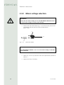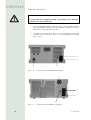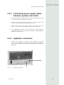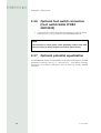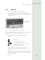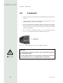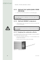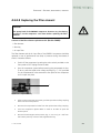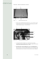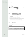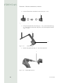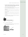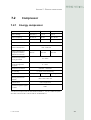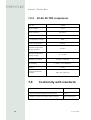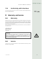
1
Operating Manual
MASTERPULS MP100
TABLE OF CONTENTS
Inhalt
1
1.1
1.1.1
1.1.2
1.1.3
1.2
1.3
1.3.1
1.3.2
1.3.3
General Information
Introduction
Indications
Contraindications
Side effects
Key
Description of controls and functional elements
MASTERPULS MP 100
Applicator
Optional ENERGY compressor for MASTERPULS MP100 (Optional)
5
5
6
7
7
8
9
9
11
13
2
2.1
2.2
2.3
2.3.1
2.3.2
2.3.3
2.3.4
2.3.5
2.3.6
14
14
14
15
15
16
17
19
19
2.3.7
Installation
Unpacking
Scope of supply
Installation
Applicator holder installation
Mains voltage selection
Connecting the compressed air supply
Connecting power supply cables between systems and socket
Applicator connection
Optional foot switch connection (Foot switch
KARL STORZ 20010230)
Optional potential equalization
20
20
3
3.1
3.2
3.3
3.4
3.5
Operation
General warnings and safety information
Start up
Functional checks
Standard settings
Treatment
21
21
23
25
25
26
4
4.1.1
4.1.2
4.1.3
4.1.4
4.1.2.1
4.1.2.2
4.1.4.2
4.2
4.3
4.4
4.4
Cleaning, maintenance, overhaul
Control unit
Applicator
Optional foot switch (KARL STORZ 20010230)
Optional ENERGY compressor
Emptying the condensate collector
Replacing the filter element
ENERGY compressor mains fuse replacement
Maintenance
Disposal
Repair
Applicator sealing ring replacement
27
27
27
28
28
28
29
33
34
34
34
35
11 301 02 0205
3
TABLE OF CONTENTS
4
4.5
4.6
4.6.1
4.6.2
Replacement of shock absorber in applicator
Overhaul
Content of the overhaul kit
Overhaul instructions
36
36
37
37
5
5.1
Trouble-shooting
Trouble-shooting
41
41
6
6.1.1
6.1.2
6.1.3
6.1.4
Accessories and spare parts
MASTERPULS MP100
Optional ENERGY compressor
Accessories
Documentation
42
42
43
43
43
7
7.1
7.2
7.2.1
7.3
7.2.2
7.4
Technichal specifications
MASTERPULS MP100
Compressor
Energy compressor
Conformity with standards
Sil.Air 50 TDC compressor
Conformity with directives
44
44
45
45
46
46
47
8
8.1
8.2
Warranty and Service
Warranty
Service
47
47
47
11 301 02 0205
CHAPTER 1 - GENERAL INFORMATION
1
General Information
1.1
Introduction
This manual contains warnings, safety instructions and specific operating
instructions in accordance with liability regulations.
CAUTION
Complete or partial failure to observe the instructions, information or
procedures preceded by the term „CAUTION“ may cause injury or fatal
accidents.
ATTENTION
Complete or partial failure to observe the instructions, information or
procedures preceded by the term „ATTENTION“ may cause equipment
damage.
NOTE
Additional information concerning specific features or operating
instructions is preceded by the term „NOTE“.
CAUTION
Before you start using the MASTERPULS MP100 for the first time, please
make sure you have read and understood all information provided in
this operating manual.
Please refer to the separate operating manual prior to any use or
overhaul of the Sil.Air 50 TDC compressor.
Familiarity with the information and instructions contained in this
manual is an essential requirement to ensure efficient and optimal use
of the system, to avoid dangers to persons and to the equipment and to
obtain good treatment results.
Thorough knowledge of the information included in this manual will
also enable you to react promptly and effectively in case of malfunctions
and failures.
11 301 02 0205
5
CHAPTER 1 - GENERAL INFORMATION
The MASTERPULS MP100 is a compressed air operated ballistic shock wave
generator featuring high-precision ballistic components in its applicator for
shock wave generation. The motion and weight of the projectile accelerated by
compressed air produce kinetic energy that is converted into sound energy when
the projectile strikes an unmoved surface (shock transmitter). This acoustic pulse
is transmitted to the target tissue by means of an acoustic impedance adapter
(shock wave coupling cushion) or gel.
NOTE
Medical devices operating on the basis of the above principle are
generally referred to as extracorporeal shock wave systems in modern
medical literature.
1.1.1
Indications
The MASTERPULS MP100 is designed for extracorporeal shock wave therapy.
Indications include:
6
-
calcaneal spur / plantar fascitis
-
muscle trigger points
A sound knowledge of trigger point therapy and trigger point shock wave
therapy (TrST) is required for therapeutic application of the MASTERPULS
MP100 in the field of trigger point shock wave therapy.
shoulder pain with or without calcifications
achillodynia
trochanteric bursitis / proximal iliotibial band friction syndrome
radial/ulnar humeral epicondylitis
patellar tendinopathy
tibial edge syndrome
insertion tendonitis in general
acupuncture
Qualified training in acupuncture and acupuncture shock wave therapy
(AkuST) is required for therapeutic application of the MASTERPULS MP100
in the field of acupuncture.
11 301 02 0205
CHAPTER 1 - GENERAL INFORMATION
1.1.2
Contraindications
Treatment with the STORZ MEDICAL MASTERPULS MP100 is not permitted in
the following cases:
-
coagulation disorders (haemophilia)
use of anticoagulants, especially Marcumar
thrombosis
tumour diseases, carcinoma patients
pregnancy
polyneuropathy in case of diabetes mellitus
acute inflammations / pus focus in the target area
children in growth
cortisone therapy up to 6 weeks before first treatment
CAUTION
Shock waves must not be applied to target areas located above air filled
tissue (lungs), nor to any regions near large nerves, vessels, the spinal
column or head.
1.1.3
Side effects
Treatment with the MASTERPULS MP100 may cause the following side effects:
-
swelling, reddening, haematomas
-
petechiae
pain
skin lesions after previous cortisone therapy
These side effects generally abate after 5 to 10 days.
11 301 02 0205
7
CHAPTER 1 - GENERAL INFORMATION
1.2
Key
Operating manual to be observed!
Applicator connector
Foot switch connector (optional)
Potential equalization
~
AC
I/0
ON/OFF switch
Application pressure in bar (pressure gauge
reading)
Analog setting of application pressure
(control knob)
M
Mode button for mode selection:
single shock / continuous shock
Single shock
Continuous shocks at 5 Hz frequency
Continuous shocks ar 15 Hz frequency /
blinking
Continuous shocks at 10 Hz frequency
∑
Applied shocks in total (digital display)
Fuse
Type B applied part
Air: 5-7bar
8
Compressed air connector
11 301 02 0205
CHAPTER 1 - GENERAL INFORMATION
1.3
Description of controls and
functional elements
1.3.1
MASTERPULS MP 100
1
2
3
4
5
6
10
Abb. 1 - 1
9
8
7
Front view of MASTERPULS MP100
1
2
3
4
5
Pressure gauge indicating selected energy level (application pressure)
Selected shock frequency symbol: single shock
Selected shock frequency symbol: 5 Hz, 10 Hz, 15 Hz
Treatment shock counter (resettable)
Shock counter reset button
6
7
8
Foot switch connector
Applicator connector
Mode button, shock frequency selector button
9 Energy level control knob (application pressure)
10 Mains switch
11 301 02 0205
9
CHAPTER 1 - GENERAL INFORMATION
1
2
3
5
Fig. 1 – 2
1
2
3
4
5
10
4
Rear view of MASTERPULS MP100
Operation shock counter (not resettable)
Mains connector
Fuse holder
Potential equalization connector
Compressed air connector (input)
11 301 02 0205
CHAPTER 1 - GENERAL INFORMATION
1.3.2
Applicator
2
1
3
4
5
6
Fig. 1 – 3
1
2
3
4
5
6
Applicator with connecting cable
Shock transmitter
Shock transmitter screw cap
Trigger button
Locking button
Shock absorber
Applicator connecting cable
Fig. 1 – 4
11 301 02 0205
Shock transmitter with sealing rings
11
CHAPTER 1 - GENERAL INFORMATION
Depending on the therapy to be performed, the applicator can be equipped with
one of the following five shock transmitters:
-
ESWT shock transmitter (Fig. 1 – 5/1) for ESWT therapy: Ø 15 mm
TrST shock transmitter (Fig. 1 – 5/2) for trigger point therapy: Ø 10 mm
AkuST shock transmitter (Fig. 1 – 5/3) for therapeutic shock wave application
in acupuncture: Ø 6 mm (Fig. 1 - 5/3) Ø 6mm
2
1
Fig. 1 – 5
-
3
ESWT, TrST and AkuST shock transmitters
Optional: Focus shock transmitter
Optional: D-Actor shock transmitter
NOTE
Always use an acoustic impedance adapter (shock wave coupling
cushion) (Fig. 1 – 6/1) in order to ensure perfect hygiene during patient
treatment.
1
Fig. 1 – 6
12
Shock transmitter with acoustic impedance adapter
11 301 02 0205
CHAPTER 1 - GENERAL INFORMATION
1.3.3
Optional ENERGY compressor for
MASTERPULS MP100 (Optional)
The ENERGY compressor provides the compressed air supply for the
MASTERPULS MP100 and can be ordered as an option.
1
Fig. 1 – 7
1
Front view of ENERGY compressor
Mains switch
1
2
3
4
Fig. 1 – 8
1
2
3
4
5
6
5
6
Rear view of ENERGY compressor
Compressed air connector (output)
Fuse holder
Mains connector
Connector for mains power link cable (mains output for MASTERPULS
MP100 control system)
Potential equalization connector
Condensate collector
11 301 02 0205
13
CHAPTER 2 - INSTALLATION
2
Installation
2.1
Unpacking
•
Remove the equipment and accessories from the packaging container.
Proceed with extreme caution.
•
Check that all items are included in the packaging container and that
they are not damaged.
•
Contact your supplier or the manufacturer immediately if any items are
missing or damaged. Retain the original packaging, if possible. It may
prove useful for any later equipment transport.
2.2
Scope of supply
The standard scope of supply of the STORZ MEDICAL MASTERPULS MP100
includes the following items:
-
Î6
14
MASTERPULS MP100 (control system)
applicator with accessories (2 shock transmitters, complete applicator
holder, acoustic impedance adapter)
mains cable
mains power link cable
compressed air tube
overhaul kit for applicator overhaul
850 ml gel
user manual (operating manual, system logbook and training records)
Please refer to Section 6 for information on ACCESSORIES AND SPARE PARTS.
11 301 02 0205
CHAPTER 2 - INSTALLATION
2.3
Installation
2.3.1 Applicator holder installation
The applicator can be fitted to the right or left side of the system as desired by
the system user. Owing to the specific shape of the applicator holder and the
location of the bores provided on the side panels of the system, the applicator
holder can be mounted either parallel to the system front (Fig. 2 – 1/1) or in an
inclined position.
•
If you wish to mount the applicator holder parallel to the system front,
fix the holder by tightening both screws (Fig. 2 – 1/).
Fig. 2 – 1
•
If you wish to mount the applicator holder in such a way that it is
inclined towards the front, then use only one screw (Fig. 2 – 2) to fix
the holder, making sure that the bevelled edge of the holder ends at the
front strip of the side panel.
Fig. 2 - 2
•
Mounting position parallel to system front
Inclined mounting position
Regardless of the installation position you choose, make sure that the
smaller holder ring points downwards.
11 301 02 0205
15
CHAPTER 2 - INSTALLATION
2.3.2
Mains voltage selection
ATTENTION
Check that the mains voltage set on the MASTERPULS MP100 matches
the local mains voltage to avoid system damage.
•
Remove the mains fuse holder (Fig. 2 – 3/1) from the rear panel of the
MASTERPULS MP100 and take off the voltage selector
(Fig. 2 – 3/3)
1
2
3
Fig. 2 – 3
Mains fuse holder
NOTE
The MASTERPULS MP100 is set to a local mains voltage of 230 VAC
when delivered.
16
•
Make sure to use only fuses that meet the requirements specified in
Table 2 – 1.
•
Replace the fuses, if necessary.
11 301 02 0205
CHAPTER 2 - INSTALLATION
Mains voltage
Fuse rating
230 / 240 VAC
2 x T 0,2 A L
100 / 120 VAC
2 x T 0,5 A L
Table 2 – 1
Fuse rating
120
100
Insert the voltage selector into the mains fuse holder in such a way
that the mains voltage visible through the glass window on the outside
of the fuse holder (Fig. 2 – 3/2) matches the local mains voltage.
240
230
•
ATTENTION
Check that the fuses installed are rated for the selected voltage!
The mains voltage of the optional compressor cannot be changed. The
compressor is available in three different versions (110 V, 115 V, 220
- 240 V).
2.3.3
Connecting the compressed air
supply
ATTENTION
The compressed air input pressure must be 5.0 - 7.0 bar. If compressors
other than the STORZ MEDICAL ENERGY compressor are used, this
pressure must be checked on the compressed air supply system.
If the pressure exceeds 7.0 bar the system‘s overpressure protection will
be tripped.
The compressed air must be dry, oil-free and filtered to ≤ 5 micron.
Never use CO2 gas for compressed air supply.
11 301 02 0205
17
CHAPTER 2 - INSTALLATION
ATTENTION
If compressed air is supplied through a wall outlet, use a pressure
reducer (max. 7 bar), if necessary.
•
Place the optional ENERGY compressor onto a solid and stable surface.
The MASTERPULS MP100 and the ENERGY compressor may be
positioned on top or beside each other.
•
Connect the compressed air tube to the compressed air connectors
provided on the compressor (Fig. 2 – 5/1) and MASTERPULS MP100
(Fig. 2 – 4/5).
2
3
4
5
Fig. 2 – 4
Connectors on the MASTERPULS MP100
1
2
3
4
Fig. 2 - 5
18
Connectors on the ENERGY compressor
11 301 02 0205
CHAPTER 2 - INSTALLATION
2.3.4
Connecting power supply cables
between systems and socket
•
Connect the mains power link cable to the mains output connector (Fig.
2 – 5/3) provided on the ENERGY compressor.
•
Connect the other end of the mains power link cable to the mains
connector of the MASTERPULS MP100 (Fig. 2 – 4/2).
•
Connect one end of the mains cable to the mains connector
(Fig. 2 – 5/2) of the compressor and the other end to the socket.
•
If the MASTERPULS MP100 is used without the optional ENERGY
compressor, the mains cable is directly connected to the MASTERPULS
MP100 and to the socket.
2.3.5
•
Applicator connection
Connect the applicator cable to the applicator connector
(Fig. 2 – 6/2) provided on the MASTERPULS MP100. Make sure that the
red spots on the cable connector match the red spots on the applicator
connector.
1
Fig. 2 – 6
11 301 02 0205
Applicator connector
2
19
CHAPTER 2 - INSTALLATION
2.3.6
•
Optional foot switch connection
(Foot switch KARL STORZ
20010230)
Connect the foot switch cable (special accessories) to the foot switch
connector (Fig. 2 – 6/1) provided on the MASTERPULS MP100.
NOTE
The optional foot switch (KARL STORZ 20010230) complies with IPX8
rating according to IEC529 (degree of protection against water).
2.3.7
Optional potential equalization
The MASTERPULS MP100 and the ENERGY compressor both feature a potential
equalization connector (see Fig. 2 – 4/4 and Fig. 2 – 5/4). Where necessary,
connections for potential equalization must be made by suitably qualified
personnel.
20
11 301 02 0205
CHAPTER 3 - OPERATION
3
Operation
3.1
General warnings and safety
information
CAUTION
The MASTERPULS MP100 must only be used by suitably qualified and
trained medical personnel.
The MASTERPULS MP100 must only be used for applications approved
by STORZ MEDICAL AG!
To avoid safety hazards, use of the system for applications other than
those specified in Section 1.1.1 INDICATIONS is not allowed!
Unplug the mains cable from the system and compressor before carrying
out cleaning and maintenance work!
Î 1.1.1
Do not use the MASTERPULS or the ENERGY compressor in potentially
explosive environments, i.e. in the presence of a flammable anaesthetic
mixture with air or with oxigen or nitrous oxide.
The optional KARL STORZ foot switch must not be used in potentially
explosive atmospheres according to classification AP as per IEC 60601.
Unplug the applicator cable from the control system before carrying out
cleaning and maintenance work. Do not reconnect the applicator until
it has been completely reassembled!
Do not try to open the system! Risk of electric shocks!
Risk of transmission of microorganisms! Disinfect the applicator after
each use! Refer to chapter 4 CLEANING for details.
Î4
ATTENTION
Check that the installation surfaces have sufficient carrying capacity to
avoid equipment damage!
The system must only be connected to properly earthed and correctly
installed shockproof sockets!
Check that the system is in perfect working order before each use.
Never cover the system when in use!
Make absolutely sure that no liquid can seep into the system housing
or applicator.
11 301 02 0205
21
CHAPTER 3 - OPERATION
ATTENTION
Equipment damage caused by failure to use the system in accordance
with its intended use or by operator errors is not covered by the
warranty.
The MASTERPULS MP100 must only be used with accessories that have
been approved by the system manufacturer. To prevent safety hazards,
unauthorized system modifications are not allowed and will void the CE
mark approval and warranty.
Disposal of the system and its components must be carried out in
accordance with national waste disposal regulations.
NOTE
The MASTERPULS MP100 as well as the ENERGY compressor meets the
requirements of the applicable electromagnetic compatibility (EMC)
standards EN 60601-1-2.
These limits are designed to provide reasonable protection against
harmful interference in a typical medical installation. The equipment
generates, uses and can radiate radio frequency energy and, if not
installed and used in accordance with these instructions, may cause
harmful interference to other devices in the vicinity. However, there is
no guarantee that interference will not occur in a particular installation.
If this equipment does cause harmful interference with other devices,
which can be determined by turning the equipment off and on, the user
is encouraged to try to correct the interference by one or more of the
following measures:
• Reorient or relocate the receiving device
• Increase the separation between the equipment
• Connect the equipment into an outlet on a circuit different from
that to which the other device(s) is connected
• Consult the manufacturer of field service technician for help.
22
11 301 02 0205
CHAPTER 3 - OPERATION
3.2
Start up
•
Switch on the compressor followed by the control system.
•
Use the control knob (Fig. 3 – 1/5) to select an initial value for the shock
application pressure (min. 1.0 bar). The selected value is indicated on the
pressure gauge (Fig. 3 – 1/1).
1
2
3
5
Fig. 3 – 1
4
Application pressure selection on control system
The maximum application pressure is limited to 4 bar. To ensure correct system
operation, a minimum 1.0 bar pressure must be selected.
•
Select the shock frequency by pressing the M (mode) button
(Fig. 3 – 1/4).
single shock
continuous shocks: 5 shocks / sec.
continuous shocks: 10 shocks / sec.
blinking
continuous shocks: 15 shocks / sec., press the
mode button for at least 2 sec.
•
Press the trigger button provided on the applicator (Fig. 3 – 2/2).
•
A single press of the trigger button will cause one shock to be
released.
•
In order to work in continuous shock mode, press and hold the trigger
button or press the locking button (Fig. 3 – 2/1) while at the same time
pressing the trigger button.
11 301 02 0205
23
CHAPTER 3 - OPERATION
•
Unlock the locking button if you wish to disable continuous shock
mode.
1
2
Fig. 3 – 2
24
Trigger button and locking button
11 301 02 0205
CHAPTER 3 - OPERATION
3.3
Functional checks
Perform the following functional checks after the system has been installed:
•
Check the control system and applicator for damage.
•
Start the MASTERPULS MP100.
•
Set the application pressure to 2.0 bar.
•
Reset the treatment shock counter on the front of the control system.
•
Release individual shocks in single shock mode.
•
Release shocks in continuous shock mode (shock frequency 5 Hz ,
10 Hz and 15 Hz).
•
Check that the triggered shocks are correctly counted on the treatment
shock counter on the front of the control system.
•
Select the maximum 4 bar application pressure.
•
Release individual shocks in single shock mode.
•
Release shocks in continuous shock mode (shock frequency 5 Hz ,
10 Hz and 15 Hz).
•
Release shocks by means of the foot switch, if used.
3.4
Standard settings
•
Before each therapy session, press the reset button (Fig. 3 – 1/3) to
reset the treatment shock counter (Fig. 3 – 1/2) provided on the control
system.
•
The number of shocks to be applied for trigger point shock wave therapy
(TrST) and acupuncture shock wave therapy (AkuST) differs from ESWT
treatment. Such therapies must only be performed by suitably qualified
and trained personnel.
•
A total of about 2000 shocks must generally be applied per therapy
session. Please refer to the MASTERPULS MP100 application brochure
for details.
•
Start the therapy at a pressure of 2 bar and a frequency of 5 Hz.
11 301 02 0205
25
CHAPTER 3 - OPERATION
3.5
Treatment
•
Perform treatment as described in the MASTERPULS MP100 application
brochure.
•
Apply a sufficient amount of coupling gel to the patient’s skin in the
coupling area and to the shock transmitter.
•
When using the acoustic impedance adapter, generously apply coupling
gel to both sides of the adapter. Bear in mind that the acoustic
impedance adapter cannot be used if treatment is performed with the
TrST shock transmitter.
•
Fit the acoustic impedance adapter into the mounting groove
(Fig. 3 – 3/1) provided on the shock transmitter screw cap.
1
Fig. 3 – 3
Mounting groove for acoustic impedance adapter
CAUTION
The MASTERPULS MP100 must only be used for applications approved
by STORZ MEDICAL AG!
Î 1.1.1
26
To avoid safety hazards, use of the system for applications other than
those specified in Section 1.1.1 (INDICATIONS) is not allowed!
11 301 02 0205
CHAPTER 4 - CLEANING, MAINTENANCE, OVERHAUL
4
Cleaning, maintenance,
overhaul
4.1 Cleaning
Regular cleaning of the system ensures perfect hygiene and operation of the
MASTERPULS MP100.
CAUTION
Prior to performing any cleaning unplug the mains cable.
4.1.1
•
Control unit
Clean the exterior of the unit with a moist cloth. Use soap water or a
mild cleaning agent.
ATTENTION
Under all circumstances the unit tubes must be protected from intruding
fluids of all kinds.
4.1.2
Applicator
The applicator must be thoroughly cleaned and disinfected after each therapy
session.
•
Remove the acoustic impedance adapter, if necessary.
•
Clean the applicator with soap water to remove the ultrasound coupling
gel.
•
We advise to open the shock transmitter screw cap and to clean the
shock transmitter as well as the screw cap separately.
•
Disinfect the applicator with a surface disinfectant.
•
The acoustic impedance adapter is not suitable for reuse.
11 301 02 0205
27
CHAPTER 4 - CLEANING, MAINTENANCE, OVERHAUL
4.1.3
•
Optional foot switch (KARL STORZ
20010230)
Clean the foot switch with soap water or a mild cleaning agent.
NOTE
The foot switch is classified as IPX8 (degree of protection against water)
according to IEC529.
4.1.4
•
Optional ENERGY compressor
Clean the exterior of the compressor with a wet cloth. Use soap water
or a mild cleaning agent.
ATTENTION
Under all circumstances the unit tubes must be protected from intruding
fluids of all kinds.
4.1.2.1 Emptying the condensate collector
The condensate collector on the rear side of the ENERGY compressor should be
emptied when three quarters full or earlier.
•
Remove the condensate collector (Fig. 4 – 1/1) from the holder on the
rear side of the compressor.
•
Empty the collector and place it back into the holder.
1
Fig. 4 – 1
28
Condensate collector
11 301 02 0205
CHAPTER 4 - CLEANING, MAINTENANCE, OVERHAUL
4.1.2.2 Replacing the filter element
CAUTION
The pump head of the ENERGY compressor becomes very hot during
operation. Let the compressor cool down before replacing the filter
element.
Contents of the filter element replacement kit (Art.-No. 14464):
1 filter element
1 allen key
1 air input filter
The filter element and the air input filter of the ENERGY compressor should be
replaced in case of performance loss (drop of pressure during the release of
shocks. Proceed as follows:
•
Switch off the compressor by setting the mains switch provided on the
front panel to OFF. Unplug the mains cable.
•
Vent the compressor system before removing the compressed air tube.
To do so, press the rapid action safety coupling (Fig. 4 – 2/1) provided
for the compressed air tube towards the rear panel of the compressor
until it snaps into place.
1
Æ
Fig. 4 – 2
System venting
•
After having vented the compressor, pull the rapid action safety coupling
back into its normal position.
•
Remove the compressed air tube from the rapid action safety coupling.
•
Turn the compressor upside down in order to be able to open the
bottom panel.
•
Remove the 4 hexagon socket screws (Fig. 4 – 3/1 to Fig. 4 – 3/4) from
the bottom panel by means of the supplied allen key.
11 301 02 0205
29
CHAPTER 4 - CLEANING, MAINTENANCE, OVERHAUL
1
4
3
Fig 4 – 3
•
2
Opening the bottom panel
Remove the condensate discharge tube (Fig. 4 – 4/1) from the L-type
screwed tube joint of the metal container. While doing so, press the
metal clamping ring (Fig. 4 – 4/2) backwards.
1
2
3
4
5
Fig. 4 – 4
30
Opening the metal container
•
Unscrew the metal container (Fig. 4 – 4/4) from its mounting,
eventually using a pair of pliers. For this purspose, please seize the nut
of the L-type screwed tube joint (Fig. 4 – 4/3).
•
The pressure filter metal container (Fig. 4 – 5/1) is equipped with a
float valve (Fig. 4 – 5/2) and sealing ring (Fig. 4 – 5/3). Make sure that
during removal of the metal container the float valve and sealing ring
remain attached to the container and do not fall into the compressor.
11 301 02 0205
CHAPTER 4 - CLEANING, MAINTENANCE, OVERHAUL
1
2
3
Fig. 4 – 5
•
Metal container with float valve and sealing ring
Screw off the white filter element (Fig. 4 – 6/1) with the black air
current control ring (Fig. 4 - 6/2).
1
2
Fig. 4 – 6
•
Removal of filterelements
Screw the air current control ring (Fig. 4 – 7/2) off the white filter
element. Dispose of the filter element (Fig 4 – 7/1). The air current
control ring will be reused.
1
2
Fig. 4 - 7
White filter element with current control ring
•
Take the new white filter element included in the filter element
replacement kit and screw it into the air control ring .
•
Install the filter element in the bottom of the pressure filter metal
container (Fig. 4 – 6/3) in the compressor.
11 301 02 0205
31
CHAPTER 4 - CLEANING, MAINTENANCE, OVERHAUL
•
If the float valve (Fig. 4 – 8/2) falls out of the new pressure filter metal
container, move it back into its original position by means of tweezers
so that the sealing pin (Fig. 4 – 8/1) is located precisely in the opening
provided inside the metal container.
1
Fig. 4 - 8
2
Float valve with sealing pin
ATTENTION
If the sealing pin is bent or if it is positioned inaccurately, the float valve
installed in the pressure filter metal container may come loose and may
not properly seal off any more!
32
•
Insert the new sealing ring provided for the pressure filter metal
container (Fig. 4 – 5/3) into the cavity on the bottom edge of the
container. Check that the sealing ring fits well. If necessary, moisten
the sealing ring to make sure it cannot fall out.
•
Screw the pressure filter metal container to the holder. Tighten it until
hand-tight.
•
Push the condensate discharge tube into the L-type screwed tube
joint.
•
Unscrew the used air input filter (Fig. 4 - 4/5), preferable using a pair
of pliers, and screw the new air input filter part of the filter element
replacement kit on to mounting.
•
Fasten the bottom panel by means of the 4 screws
•
Fasten the compressed air tube in the rapid action safety coupling.
•
Plug in the mains cable.
11 301 02 0205
CHAPTER 4 - CLEANINIG, MAINTENANCE, OVERHAUL
4.1.4.2 ENERGY compressor mains fuse
replacement
The holder of the mains fuse is located at the rear panel of the compressor (see
Fig. 1 - 8/2).
•
Push the clip of the mains fuse holder (Fig. 4 - 9/1) upwards and take
the holder off the housing.
1
Fig. 4 - 9
•
Mains fuse holder
Pull the old fuses out of the fuse holder (Fig. 4 - 10/1).
1
Fig. 4 - 10
Fuse replacement
•
Replace the fuses.
•
Push the fuse holder back in to the opening until engaged.
11 301 02 0205
33
CHAPTER 4 - CLEANING, MAINTENANCE, OVERHAUL
4.2
Maintenance
Preventive maintenance is not necessarily required. However, regular
maintenance may help to identify possible defects at an early stage and thus
increase the safety and service life of the equipment.
Maintenance services can be ordered from our regional representatives in your
area or directly from STORZ MEDICAL AG.
We recommend that functional and safety checks be performed at least once a
year. National accident prevention regulations and test and inspection intervals
prescribed for medical devices must, of course, be observed.
NOTE
For further details on content and performance of the safety checks
please contact your local dealer.
Perform the following tests in order to ensure perfect functioning of the
MASTERPULS MP100 and the ENERGY compressor.
1. Leakage current test at chassis < 100 µΑ
2. Earth impedance test (incl. applicator housingl) < 0,2 Ohm
(with mains cable)
3. Power consumption test <= rated power
For additional information on the overhaul of the Sil.Air 50 TDC compressor
please refer to the separate operating manual.
4.3
Disposal
When disposing of the present medical device products no special measures
have to be observed. Please proceed in accordance with the national regulations.
After expiration of their life time, dispose the MASTERPULS MP100 and the
ENERGY compressor as electronical scrap.
Additional information about the disposal of the Sil.Air 50 TDC compressor
please find in the separate operating manual.
4.4
Repair
Repair work on defective equipment must only be carried out by personnel
suitably authorized by STORZ MEDICAL. Only original STORZ MEDICAL spare
parts must be used for this purpose.
34
11 301 02 0205
CHAPTER 4 - CLEANING, MAINTENANCE, OVERHAUL
4.4
Applicator sealing ring
replacement
NOTE
The applicator is equipped with a projectile safety catch device in order
to prevent the projectile from exiting in case a shock is released while
shock transmitter as well as shock transmitter screw cap are taken off.
The safety catch is also activated when the shock transmitter screw cap
is not well tightened or the sealing ring between screw cap and shock
transmitter is missing, respectively at the shock transmitter endings two
sealing rings old/new come together.
Once the projectile gets caught by the safety catch, it can be pushed
back into the guide tube using reasonable force.
If this is repeatedly the case or if it is impossible to release the projectile
or if the receptory edge is defectous, the applicator shaft should be
replaced .
The applicator sealing rings must be replaced after about 250,000 shocks or
earlier if leaks are identified on the applicator. Proceed as follows:
•
Switch off MASTERPULS MP100.
•
Unplug the applicator cable from the MASTERPULS MP100.
•
Screw off the shock transmitter screw cap (Fig. 4 – 9/1).
•
Remove both sealing rings (Fig. 4 – 9/2) and dispose of them.
ATTENTION
Make sure that no worn sealing rings are in the screw cap or
applicator!
•
Clean shock transmitter and shock transmitter screw cap from
remaining oil.
•
Fit two new sealing rings to the shock transmitter (Fig. 4 – 9/5).
•
Place the shock transmitter with the new sealing rings into the shock
transmitter screw cap.
•
Firmly screw the shock transmitter screw cap to the applicator.
11 301 02 0205
35
CHAPTER 4 - CLEANING, MAINTENANCE, OVERHAUL
1
2
3
4
5
Fig. 4 – 11
4.5
Sealing ring replacement
Replacement of shock
absorber in applicator
•
Remove the old shock absorber (Fig. 4 – 11/4) with a pointed object
(screwdriver).
•
If necessary, remove remaining adhesive elements.
•
Take the new shock absorber included in the applicator overhaul kit
and remove the protective film from the two adhesive strips.
•
Push the new shock absorber into the cavity on the applicator handle
until it snaps into place in the cavity frame.
4.6
Overhaul
Shock waves are generated mechanically. Due to the effects of friction, the
applicator components are continuously exposed to mechanical stress that will
cause minor wear.
NOTE
The applicator should be overhauled about every 750,000 shocks. Using
the overhaul kit that includes all required wear parts, the applicator can
be overhauled easily and quickly by the user of the equipment.
36
11 301 02 0205
CHAPTER 4 - CLEANING, MAINTENANCE, OVERHAUL
4.6.1 Content of the overhaul kit
Article no.
Product description
13692
ESWT shock transmitter (Ø 15 mm) with sealing rings
13280
Projectile
13271
Guide tube
15558
Sealing rings MP100
13677
Fork wrench (jaw size 22)
13479
Box with protective foam sheets
13272
Shock absorber
The overhaul kit can be ordered from your dealer quoting order number
13460.
4.6.2 Overhaul instructions
NOTE
The applicator is equipped with a projectile safety catch device in order
to prevent the projectile from exiting in case a shock is released while
shock transmitter as well as shock transmitter screw cap are taken off.
The safety catch is also activated when the shock transmitter screw cap
is not well tightened or the sealing ring between screw cap and shock
transmitter is missing, respectively at the shock transmitter endings two
sealing rings old/new come together.
Once the projectile gets caught by the safety catch, it can be pushed
back into the guide tube using reasonable force.
If this is repeatedly the case or if it is impossible to release the projectile
or if the receptory edge is defectous, the applicator shaft should be
replaced .
•
Switch off the MASTERPULS MP100.
•
Unplug the applicator cable from the control system.
•
Place the applicator onto a dry, clean and dust-free surface.
11 301 02 0205
37
CHAPTER 4 - CLEANING, MAINTENANCE, OVERHAUL
•
Screw off the shock transmitter screw cap (Fig. 4 – 12/1).
2
1
Fig. 4 – 12
•
Applicator overhaul
Using the supplied fork wrench (Fig. 4 – 13/1), remove the shaft (Fig.
4 – 13/2) from the applicator and pull it out of the applicator handle
(Fig. 4 – 13/3).
1
2
3
Fig. 4 – 13
•
Shaft removal
Remove the guide tube (Fig. 4 – 14/1) from the shaft.
1
Fig. 4 – 14
38
Guide tube removal
11 301 02 0205
CHAPTER 4 - CLEANING, MAINTENANCE, OVERHAUL
•
A magnet is provided in the applicator handle (Fig. 4 – 13/3) to hold the
projectile. To remove the projectile, hold the applicator handle in such
a way that its opening points downwards. Slightly knock the handle
against the table surface until the projectile falls out.
•
In case the projectile breaks apart due to overloading, projectile
fragments may be located inside the guide tube.
•
Dispose of the worn guide tube and of all worn shock transmitters and
sealing rings.
•
Clean the shaft and shock transmitter screw cap with alcohol. These
parts will be reused.
•
Make sure to place all cleaned components onto a dry, clean and dustfree surface.
•
Take the new guide tube, projectile and sealing rings included in the
overhaul kit.
•
Insert the guide tube (Fig. 4 – 15/3) into the opening in the applicator
handle (Fig. 4 – 15/1) up to the limit stop.
1
2
Fig. 4 – 15
Guide tube and projectile fitting
•
4
Make sure that the guide tube end inserted into the applicator handle is
the one featuring two air slots (Fig. 4 – 16/1).
1
Fig. 4 – 16
11 301 02 0205
Guiding tube air slots
39
CHAPTER 4 - CLEANING, MAINTENANCE, OVERHAUL
•
Insert the new projectile (Fig. 4 - 15/3) into the fitted guide tube.
•
Screw the shaft into the applicator and tighten it by means of the
supplied fork wrench until hand-tight.
•
New shock transmitters come with new sealing rings. Thus, only replace
the sealing ring on the shaft (Fig. 4 - 12/2).
ATTENTION
Make sure that no worn sealing rings are in the shock transmitter
screw cap and on the shaft end!
Î 3.3
40
•
Replace the shock absorber.
•
Screw the screw cap with the required shock transmitter back onto the
shaft.
•
Carry out a functional check of the applicator as described in Section
3.3 (FUNCTIONAL CHECKS).
11 301 02 0205
CHAPTER 5 - TROUBLE-SHOOTING
5
Trouble-shooting
5.1
Trouble-shooting
CAUTION
Unplug the mains cable from the system before you carry out any
maintenance work!
Fault
Possible cause
Corrective actions
System does not work
Power failure
Check the power
supply.
Operating mode LED
not lit
Defective mains fuse
Replace the fuses.
Defective mains plug
Replace the mains
cable.
Defective foot switch
connecting cable
Check the cable and
tube connections
and replace them, if
necessary.
No compressed air
supply
Leaks on applicator
cable or cable not
properly connected
Compressed air tube
not connected or not
correctly fastened with
safety coupling
Check the compressor
air filter and replace it,
if necessary.
Clogged compressor air
filter
No shock wave power
output
No compressed air
supply
Check the compressed
air supply.
Blocked or worn
projectile
Take applicator apart.
Clean the guide tube
and projectile.
Overhaul the applicator.
11 301 02 0205
41
CHAPTER 6 - ACCESSORIES AND SPARE PARTS
6
Accessories and spare parts
6.1.1
MASTERPULS MP100
Holder, complete
13701
Compressed air tube
Compressed air tube for compressor, 1 m long
13463
Compressed air tube for compressor, 3 m long
13447
Compressed air tube for central compressed air
supply
13464
Mains cable
Mains cable CEE 7 Europe, 4 m long
(for control system or SMAG compressor)
13455
IEC coupling, 1 m long
(between control system and compressor)
13546
Applicator
Ø 15 mm ESWT shock transmitter set
13476
Ø 10 mm TrST shock transmitter set
13457
Ø 6 mm AkuST shock transmitter set
13458
Ø 20 mm D-Actor shock transmitter set
13459
Ø 15 mm Focus shock transmitter set
15100
Applicator shaft
14615
Applicator shaft with notch
15236
Overhaul
42
Applicator overhaul kit
13460
D- actor overhaul kit
13477
11 301 02 0205
CHAPTER 6 - ACCESSORIES AND SPARE PARTS
6.1.2
Optional ENERGY compressor
Filter replacement set
14464
Insulating pad
14463
6.1.3
Accessories
Gel bottle set (10 bottles)
13473
MASTERPULS MP100 transport suitcase
(for control system or Energy compressor or Sil.Air 50
TDC compressor)
13472
MASTERPULS MP100 transport suitcase
(for control system or compressor)
11608
MASTERPULS MP100 Trolley
13471
MASTERPULS MP100 Trolley with compressor covering
15149
Foot switch (KARL STORZ 20010230) incl. connection
cable
10103
Acoustic impedance adapter
13470
F- Meter
15323
6.1.4
Documentation
MASTERPULS MP100 user manual
German/English/French
11 301 02 0205
13833
43
CHAPTER 7 - TECHNICAL SPECIFICATIONS
7
Technichal specifications
7.1
MASTERPULS MP100
Operating modes
single shock, continuous shock 5 Hz /
10 Hz /15 Hz
Energy selection
continuously adjustable
Max. sound pulse amplitude
14,3 MPa
Mains input voltage
100 / 120 / 230 / 240VAC ~ +10%
Mains frequency
50 / 60Hz
Mains fuse
230 / 240VAC : 2 x T 0,2 A L
100 / 120VAC : 2 x T 0,5 A L
Power consumption
40 VA
Compressed air supply
5 - 7 bar
Compressed air output
Max. 4 bar
Ambient temperature during
operation
10 – 40°C
Ambient temperature during
storage and transport
0 – 60°C
Ambient air pressure
500 hPa - 1060 hPa
Air humidity
5 – 95%, non condensing
Control system weight
5,2 kg
Applicator weight
0,44 kg
Housing dimensions (wxhxd)
305 x 155 x 233 mm
Classification
Class I equipment
Protection against ingress of
water
IPX0
This device complies with the standards EN 60601-1, C22.2 Nr. 601.1-M90 and
UL std N0 60601-1.
44
11 301 02 0205
CHAPTER 7 - TECHNICAL SPECIFICATIONS
7.2
Compressor
7.2.1
Energy compressor
Art. No.
13465
13466
13476
Mains voltage
220-230 V
115 V
100 V
Mains frequency
50 / 60 Hz
60 Hz
50 / 60 Hz
Mains fuse
T 5 A L (SB)
T 6,3 A L (SB) T 6,3 A L (SB)
Compressed air output
6 bar
Power consumption
Power consumption:
compressor without
additional consumer
max. 1225 VA
450 VA
500 VA
500 VA
Ambient temperature
during operation
10 – 40°C
Ambient temperature
during storage and
transport
0 – 60°C
Ambient air pressure
500 hPa - 1060 hPa
Air humidity
Weight
Housing dimensions
(wxhxd)
Classification
Protection against ingress
of water
5 – 95%, non-condensing
10,9 kg
10,2 kg
10,2 kg
305 x 155 x 233 mm
class I equipment
IPX0
This device complies with the standards EN 60601-1, art. No 13466 complies
also with C22.2 Nr. 601.1-M 90 and UL std N0 60601-1.
11 301 02 0205
45
CHAPTER 7 - TECHNICAL DATA
7.2.2
Sil.Air 50 TDC compressor
Art. No.
14588
Mains voltage
230 V
Mains frequency
50 / 60 Hz
Mains fuse
T 2,4 A L (SB)
Compressed air output
8 bar
Power consumption
340 VA
Ambient temperature
during operation
10-30°C
Ambient temperature
during storage
-10 - (+)40°C
Ambient air pressure
500 hPa - 1060 hPa
Air humidity
5 - 95% , non condensing
Weight
22 kg
Housing dimensions
(wxhxd)
7.3
380 x 330 x 290 mm
Conformity with standards
EN 60601-1
46
- Type of protection against electric shocks:
class 1
- Degree of protection against electric shocks:
type B applied part
11 301 02 0205
CHAPTER 8 - WARRANTY AND SERVICE
7.4
Conformity with directives
This medical product bears the CE mark in accordance with the Medical Device
Directive (MDD) 93/42/EEC.
8
Warranty and Service
8.1
Warranty
During the two years‘ warranty period from the date of delivery of the product
to the end customer, defects will be remedied at no charge to the customer
upon the customer furnishing adequate proof that the defect is due to defects
in material or workmanship. Shipping costs and risk of loss of returned products
shall be borne by the customer.
Please complete the attached warranty card and return it as soon as possible to
the address below:
STORZ MEDICAL AG
Unterseestrasse 47
8280 Kreuzlingen
Switzerland
ATTENTION
Any unauthorized opening, repair or modification of the system will
relieve the manufacturer of its liability and responsibility for safe
system operation and will automatically void the warranty even before
the end of the warranty period.
8.2
Service
Should you have any further questions or require additional information, please
feel free to call your dealer.
11 301 02 0205
47