1
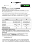
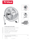
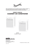
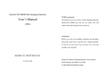
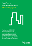
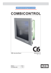
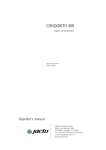
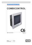
USER MANUAL
INSTRUCTIONS FOR MOUNTING
STAVOKLIMA v.o.s
1
DITRONIC-MANUAL
REGULATOR AND SYSTEM DESCRIPTION
Regulator Ditronic and Ditronic plus is processor regulator intended for air curtains
control. The regulator is intended only for wall mounting for basic environment
without a humidity.
Button ON/OFF
Fan button (listing up)
+ button (listing right)
Heating button (listing down)
- button (listing left)
ENTER button (confirmation and
entering the setting part)
Icon of time regime activation
Icon of the door position (door contact)
Setting of fan grade
Icon of heating regime activation
Icon of external contact or remote control
connection
Icon of parallel air curtain connection (y)
Medium temperature / outlet air
signalisation
Heating grade setting
Icon of associated failure
Requested / room temperature
signalisation
Icon of automatic regime activation
Icon of keyboard lock
Technical conditions for the regulator running:
max. environment temperature 35°C / degree of prote ction IP 20
running voltage of the regulator 12V DC
running unit voltage 230V(400V) - 50Hz (if not ordered differently)
STAVOKLIMA v.o.s
2
DITRONIC-MANUAL
REGULATOR UNPACKING, MOUNTAING
The regulator Ditronic (plus) is delivered as a set with the room sensor,
shortened manual for quick service, user manual and mounting
accessories (connectors, screws) and mounting model. Firstly check the
correctness of the cabel* (recommended cabel is UTP - 8 leads; for
example ROLINE U125H424-A etc.), afterwards you enclose the model to
fit the anchorage screws, mark the holes for drilling. Mind the right
placement of the cable, as it is marked on the model. Afterwards drill the
holes o8 for connectors and fit the connectors with screws according to the
enclosed model (pic. 1). The screws screw up to the wall almost complete
with a distance of cca. 1,5 mm for steady fitting of the regulator anchorage
plate (pic. 2).
!!! Place the cabel always into the protective pipe !!!
* cabel type can be different according to the habbits of each country and distributor
pic. 1 - model
pic. 2 - anchorage plate
Shorten the cabel afterwards ( 8 leads) for the distance of 10 cm from the wall
and fit the end of the cabel. Mind the right fitting of the wires see pic. 3 (the
same on the both ends of the cabel). Before fitting the regulator on the wall,
plug in the connector into the regulator socket. Place the cabel in that way, that
it won´t overhang the outline of the anchorage plate. Slide on the regulator with
the anchorage plate on the screws and movement down you will finish the
mounting. To secure the regulator against steeling, you can secure the screws
by fully tightening up (pic. 4).
pic. 3 - connector connection 8 PIN
STAVOKLIMA v.o.s
3
DITRONIC-MANUAL
pic. 4 - regulator placement on the wall
pic. of the regulator
mounting on the wall and
event. securing the
screws with the key
Attention !!! Before regulator connection (connection under voltage) check the
righteness of all cabels in the unit electronic. Also check the rightness of the
preliminary element according to the project documentation.
STAVOKLIMA v.o.s
4
DITRONIC-MANUAL
SHORTENED INSTRUCTIONS FOR QUICK CONTROL
ON - OFF
With the button ON-OFF you can switch ON/OFF the unit. The setting of the fan and
heating grade will be saved afterwards and unchanged. This button is superior
before all other functions incl. the keyboard lock.
FAN
You can choose the fan grade via the buttons "+" and "-" ; selected grade
is indicated by the symbol " _ " , after 1 sec it will be saved automatically
into the memory.
HEATING
You can choose the heating grade (for water heated version - control by
electrothermic valve /if it is used/ ; for electric version control of electric
heater) via the buttons "+" and " -" ; selected grade is indicated by the
symbol " _ " , after 1 sec it will be saved automatically into the memory.
The heating is activated only if it is needed from the achieved
temperatures.
REMOTE RADIO CONTROL
This function is active only if it was permited in the user level. It allows to
remote control the unit ON/OFF wireless (key-rack). Active contact is
indicated via lighting icon, disconnection by this contact - blinking icon.
Activation of this function eliminates the control via external contact.
SUPERIOR SYSTEM - BMS
This function is active only if it was permited in the user level (UU). All the
hand controls (fan and heating buttons) is blocked. All the setting are
controled by superior system BMS. If there was activated in "UU" the
button BMS-hand, it is possible to switch off the system BMS for a short
time and control the unit in hand mode. The hand mode activation is made
by pressing the button " - " for 5 s. Active control BMS is indicated via
lighting icon, control in hand mode - blinking icon.
STAVOKLIMA v.o.s
5
DITRONIC-MANUAL
PARALEL UNIT(S)
The system automatically supports the paralel connection of other units to
one control. If other unit is connected into the control electronic, the icon
"master/ slave" is activated. All paralle "slave" units follows the unit
"Master". Protective functions on the units "slave" are active autonomously.
KEYBOARD LOCK
Against undesirable change-over or unit control it is possible to lock the
keyboard. Locking and unlock is made by pressing the buttons "+" and "-"
for 6 s at the same time. The lock activation is indicated via light up icon.
For the safety reason the button "ON/OFF" is not brought to the lock.
HEAT UP REGIME
This function is active only if it was permitted in the user level. It allows
casual covering of the losses in the room (immediate heating). By pressing
the button " - " for 5 s, + ENTER it will activate the heat up regime for the
time setted in the UU. By pressing any button it will change over to
standard regime.
TEMPERATURE OF OUTLET AIR
This icon signals the air temperature coming out of the unit. From this sensor is also
activated the anti-frost protection of the heat exchanger. The sensor also restricts
the minimum outlet temperature.
STAVOKLIMA v.o.s
6
DITRONIC-MANUAL
DOOR
This icon is active only if it was setted in the user level of the unit control by
the door (door contact). The icon signals the door position (closed/open).
After the door closing, the unit will be switched off (with time delay), if the
automatic regime "A" was not activated.
TIME REGIME
This icon is active only if the clock and the switch times were
setted. If the unit is in setted time period, when it should work, this
icon is lighted up on the display.
REAL TIME AND THE DAY OF THE WEEK
The regulator allows to control the unit according to the week time regime. The
regime selects in the user mode (access via button ENTER). There are 2 control
possibilities available, namely 1-7 or 1-5 and 6-7, where the small number means
the day of the week (1=Monday; 7 = Sunday). The time regime is setted always in 24
hour regime.
EXTERNAL CONTACT
This function is active only if it was permited in the user level. It allows
external control (permission to switching on) from the superior place. If the
contact is off, the unit can not be switched on. Active contact is signed via
lighting icon, disconnection by this contact - blinking icon. Activation of this
function eliminates to control the unit via remote radio control..
ANTI-FROST PROTECTION
This icon is activated automatically. In the factory settings it is setted on
10°C. At the water heated version is the anti-frost protection watched in 2
places (heat exchanger and space) and it is two-phase. Reaching the antifrost temperature it will light up the icon of anti-frost protection and the
failure relay will be connect. If the temperature still falls down, the acoustic
warning signal is active. At the electro version is watched only the anti-frost
protection of the room.
STAVOKLIMA v.o.s
7
DITRONIC-MANUAL
AUTOMATIC REGIME
This function is active only if it was permited in the user level. It allows
automatic operation according to the door position (door contact). If the
door is closed, while activation of this function the unit switch over into the
min. heating and fan grades automatically. Repeat door opening it will
switch over into the setted grades. Active regime is signaled via lighting
icon.
ASSOCIATED FAILURE
The system picks out any failure of the unit (the communication, motor
failure, sensor failure, anti-frost protection etc.). If the failure comes, the
icon lights up and the failure relay connects for signalisation.
ROOM AND MEDIUM TEMPERATURE
This icon signals the room temperature, where the unit is installed.
This icon signals the medium temperature coming into the unit. This icon is
active only at the water heated version.
REQUESTED TEMPERATURE
The regulator offers in "user mode (UU)" selection of two possible
temperatures, according to which the unit will be controled (outlet sensor or
room sensor). The device controls the setted temperature in "UU". Via
buttons "+" and "-" it is possible to make the temperature correction.
STAVOKLIMA v.o.s
8
DITRONIC-MANUAL
USER LEVEL - MANUAL
The settings in the user level allow to use lots of other additional functions,
which are not accesible to the basic level. Because there are mostly
important technological changes in the functions and unit running, we
recommend that a qualified and trained person will work with this level.
Entry and exit (level escape) is done by longer pressing the butten ENTER.
Entry into the control line is done by pressing the butten "ENTER",
selection (change) is done by "+" and "-" and saving again via "ENTER".
1
WEEKLY SWITCHING CLOCK
The regulator offers the possibility to control the unit according to the time
regime selected by the user. The current time and switching time you can
set see underneath of the chapter. If you want to control the unit according
to the time regime choose "ON".
2
WEEKLY SWITCHING CLOCK - SETTING
If you have on the line "1" chosen the weekly clock "ON" you can set or change the
current time - choose "YES". The time is setted in 24h regime. At least 1x in 6
months check the time reality. If you set the time once, it is saved in the regulator
memory automatically (event. after the failure of current it it will download the right
time). This line is active only if you have choosen to control the unit according to the
time clock (line 1).
3
TIME SETTING - CLOCK
Here you can set (change) the real time - HOUR. This line is active
only if you have choosen to control the unit according to the time
clock (line 1).
4
TIME SETTING - MINUTES
Here you can set (change) the real time - MINUTES. This line is active only
if you have choosen to control the unit according to the time clock (line 1).
STAVOKLIMA v.o.s
9
DITRONIC-MANUAL
5
DAY IN A WEEK SETTING
Here you can set (change) the real day in a week. Monday = 1 / Sunday =
7. This line is active only if you have choosen to control the unit according
to the time clock (line 1).
6
SETTING OF THE WEEK SWITCHING SELECTION
Options for switching clock you can choose the same for all days (option 17 ON) or separately for working days and separately for days 6,7 (1-5,6-7,
ON). Monday = 1 / Sunday = 7. This line is active only if you have choosen
to control the unit according to the time clock (line 1).
7
CONTROLLING SENSOR SELECTION
For temperature regulation you can choose from 2 sensors. Room sensor
or sensor of outelt air.
8
PRE-SETTING OF REQUIRED TEMPERATURE
Here you can set the required temperature from selected type of sensor (line 7). This
temperature can be corrected with the buttons "+" and "-". After unit switching off it will download
again the pre-setted temperature without the correction.
9
ROOM SENSOR CORRECTION
If you were not able to place the sensor ideally because of the architectonic
or space reasons and the sensor measures distorted data, you have the
possibility to shift the meassured temperature +, - °C through this
correction. It is also necessary to use this correction while excessive
sunshine or sensor cooing. See page 17
STAVOKLIMA v.o.s
10
DITRONIC-MANUAL
10
SUPERIOR SYSTEM (BMS)
This option is when required to control the unit from superior system. You
can use 3-grade control of fan and heater as a standard. Further linked
control possibilities (0-10V) has to set authorized technician and it is not a
part of this user level (it is not mentioned in the price list - see price list of
service works). These entries are freepotential contacts. Mind to always
switch on only 1.grade of the heater and fan capacity. When choosing this
function you will loose manual control above the regulator (the unit will be
fully controlled via BMS expect the button HOTKEY (line 11). Active regime
BMS is signaled via lighted icon. BMS connection is made in the unti
electronic and it is obvious from the delivered documentation. Max contact
load is 24V/3A/AC-15.
11
HAND CONTROL AT THE SYSTEM BMS
For the case, that it will be necessary to cut off the unit for a short-term
from BMS, you can allow the "hand control" at BMS. This function is active
only if the regime BMS is allowed. Change into hand regime is possible
when pressing the button " -" for 2 s. Afterwards you can control the unit in
hand regime, without dependence on BMS. Next pressing of " -" will cause
fully change to BMS regime (deactivation of hand regime). Hand regime at
BMS is signaked via lighted icon.
12
SOUND
Setted fan and heater grades are acoustically signaled. 1-grade = 1x
sound. You can switch off the sound throug the option "OFF".
13
KEYBOARD LOCK
You can lock the keyboard for the case of not willing to control the regulator. If you
wish to lock the keyboard, choose "ON". After the time of 3s and none change has
been made in the basic level, the keyboard will lock. Unlock and back lock you can
make when pressing the buttons "+" and "-" for 2s at the same time. For the safety
purpose the only button "ON/OFF" is still active, even the keyboard is locked.
STAVOKLIMA v.o.s
11
DITRONIC-MANUAL
14
EXTERNAL CONTACT
This function allows external control (switch on allowance) from the
superior place. If the contact (free potential contact) is switched off,
the unit can not be switched on. Active contact is signaled via
lightened icon, disconnection - blinking icon. Activation of this
function eliminate to control the unit via remote radio control. Max.
contact loading 24V/3A/AC-15.
15
REMOTE RADIO CONTROL
This function allows remote control of the unit ON/OFF wireless . Active
contact is signaled via lightened icon, disconnection with this contact blinking icon. Activation of this function eliminate to control the unit via
external contact. Mind the right channel settings (switch DIP) of the
receiving part of the control (placed in the unit). The remote control is not a
standard part of the delivery (optional).
16
DOOR CONTACT
This function allows to control the unit according to the door position (door
contact). The icon signaled the door position (closed/open). After the door
close the unit will switch off (with time delay), if the automatic regime
wasn´t activated " A "(line 21). It is a free potential contact. As a contact
you can use a contact of the electronic of the automatic door shifting or
mechanicla or magnetical door contact (delivered as an accessorie when
requested). Max. contact loading 24V/3A/AC-15.
17
DOOR CONTACT POSITION
If your selected door contact (door position) doesn´t correspond to the icon
signalling it is necessary to choose the reverse stage of this contact.
Change of the switching contact will lead to the right contact position to the
regulator icon. This setting is active only, if the door contact was allowed
(line 16).
STAVOKLIMA v.o.s
12
DITRONIC-MANUAL
18
TIME DELAY OF THE DOOR CONTACT
Concerning the unit lifetime and because of the reason of steady unit
running it is sensible to choose the optimal time delay of the unit after the
door close (switch off the door contact). Don´t set the time too short,
recommended time is 60s (see factory settings). Range of setting 30-240s
step 5s. This setting is active only in that case, that the door contact was
allowed (line 16).
19
HEAT UP REGIME
For the case, that it will be necessary to cover with the air curtain also casual heating
losses, there is an inbuilt function into the regulator of heat up regime. When
activating this function the unit will be switch on at maximum fan and heating
capacity, which the unit allows. Heat up regime is running for the time setted in the
line 20. When pressing the button "Heating" for 5s you will activate the heat up
regime. Afterwards it is necessary to confirm this option with the button "ENTER".
Deactivation that means return into the previous setting you can make via any
button.
20
TIME OF HEAT UP REGIME
If you have allowed the heat up regime of the unit you can set the time for
how long will the heat up regime work. Range of setting 3-15min step
0,5min.
21
AUTOMATIC REGIME OF THE UNIT
This function allows automatic running of the uni according to the door position (door
contact). When the door is closed and the function is activated the unit will
automatically switch over into the min. grade of heating and fan. Repeated door
opening will cause switch over into the setted grades. Active regime is signaled via
blinking icon. The door contact will automatically release and set, if you will choose A
="ON".
STAVOKLIMA v.o.s
13
DITRONIC-MANUAL
22
SWITCHING OFF THE HEATING REGIME - WINTER/SUMMER
For the economic purposes lots of moder heating systems don´t have the
preparation (heating) of the heating medium in the summer time. If you
don´t use such a system and you require DON´T HEAT in the summer
time while sudden temperature drop choose the regime SUMMER =
"OFF". The heating will be passive (expect the anti-frost protection) in this
regime.
23
ANTI-FROST PROTECTION
There is an inbuilt anti-frost protection (PO) because of the possibility of
exchanger freezing (only at water heated versions). When achieving this
temperature it will switch on the relay failure outlet in the unit electronic and this
will cause the valve opening (only if the electrothermic valve is used). If the
temperature still drops the fan will be switched off and the acoustic signal about
danger is active.The regulator watches also the anti-frost room temperature as
standard. Setting for water heated version: setted temperature of PO of the
heat exchanger - see regulator line, PO room temperature = value +3°C
automatically. Setting for electro version: setted temperature of room PO - see
regulator line. In the air curtains connected in the system Master/Slave is the
PO watched autonomously at each air curtain. You can change some
parametres in the service technicians level. Ask the authorized service of the
producer. (it is not included in the price - see price list of service works).
24
SWITCH ON TIME - REGIME 1÷5 ; HOURS
Time setting "HOURS" SWITCH ON for the selection "1-5".This line is active
only, if you have choosen the control according to the time clock (line 1).
25
SWITCH ON TIME - REGIME 1÷5 ; MINUTES
Time setting "MINUTES" SWITCH ON for the selection "1-5".This line is
active only, if you have choosen the control according to the time clock
(line 1).
STAVOKLIMA v.o.s
14
DITRONIC-MANUAL
26
SWITCH OFF TIME - REGIME 1÷5 ; HOURS
Time setting "HOURS" SWITCH OFF for the selection "1-5".This line is
active only, if you have choosen the control according to the time clock
(line 1).
27
SWITCH OFF TIME - REGIME 1÷5 ; MINUTES
Time setting "MINUTES" SWITCH OFF for the selection "1-5".This line is
active only, if you have choosen the control according to the time clock
(line 1).
28
SWITCH ON TIME - REGIME 6; HOURS
Time setting "HOURS" SWITCH ON for the selection "6".This line is active
only, if you have choosen the control according to the time clock (line 1).
29
SWITCH ON TIME - REGIME 6; MINUTES
Time setting "MINUTES" SWITCH ON for the selection "6".This line is
active only, if you have choosen the control according to the time clock
(line 1).
30
SWITCH OFF TIME - REGIME 6; HOURS
Time setting "HOURS" SWITCH OFF for the selection "6".This line is
active only, if you have choosen the control according to the time clock
(line 1).
31
SWITCH OFF TIME - REGIME 6; MINUTES
Time setting "MINUTES" SWITCH OFF for the selection "6".This line is
active only, if you have choosen the control according to the time clock
(line 1).
32
SWITCH ON TIME - REGIME 7; HOURS
Time setting "HOURS" SWITCH ON for the selection "7".This line is active
only, if you have choosen the control according to the time clock (line 1).
STAVOKLIMA v.o.s
15
DITRONIC-MANUAL
33
SWITCH ON TIME - REGIME 7; MINUTES
Time setting "MINUTES" SWITCH ON for the selection "7".This line is
active only, if you have choosen the control according to the time clock
(line 1).
34
SWITCH OFF TIME - REGIME 7; HOURS
Time setting "HOURS" SWITCH OFF for the selection "7".This line is
active only, if you have choosen the control according to the time clock
(line 1).
35
SWITCH OFF TIME - REGIME 7; MINUTES
Time setting "MINUTES" SWITCH OFF for the selection "7".This line is
active only, if you have choosen the control according to the time clock
(line 1).
36
SWITCH ON TIME - REGIME 1÷7 ; HOURS
Time setting "HOURS" SWITCH ON for the selection "1-7".This line is
active only, if you have choosen the control according to the time clock
(line 1).
37
SWITCH ON TIME - REGIME 1÷7 ; MINUTES
Time setting "MINUTES" SWITCH ON for the selection "1-7".This line is
active only, if you have choosen the control according to the time clock
(line 1).
38
SWITCH OFF TIME - REGIME 1÷7 ; HOURS
Time setting "HOURS" SWITCH OFF for the selection "1-7".This line is
active only, if you have choosen the control according to the time clock
(line 1).
39
SWITCH OFF TIME - REGIME 1÷7 ; MINUTES
Time setting "MINUTES" SWITCH OFF for the selection "1-7".This line is
active only, if you have choosen the control according to the time clock
(line 1).
40
STANDARD FACTORY SETTINGS
Option for overwriting the memory into the first setting = factory setting.
STAVOKLIMA v.o.s
16
DITRONIC-MANUAL
REMOVAL OF EASY BREAK-DOWNS
the unit
fails to
heat
too high temperature against required
check
aerating system, not sufficient medium temperature
check
electrothermic valve failure (if it is used)
check, exchanging
disconnection of anti-damage thermostat
find out the cause
the unit disconnected or faulty sensor
indicates anti-frost protection
a failure faulty thermocontact or motor (if it is used)
the regulator
doesn´t react
to the buttons
the regulator
doesn´t react,
display
doesn´t light
check, exchanging
find out the cause
check, exchanging
locked keyboard
unblock
activated system BMS
adjust, check
failure of regulator processor
reset (switching off/voltage
switch on)
not functional air curtain´s current supply
check, exchanging
not functional fuse in the unit´s electronic
check, exchanging
not functional baterie in the Ditronic regulator
check, exchanging
error in the regulator´s processor when reseting the
programm (LED green lights constantly)
reset (switching off/voltage
switch on)
MASTER-SLAVE SYSTEM
The regulators Ditronic support as standard the connection possibility of other
parallel devices. Under the condition for their function is the right connection and
respecting the same types of air curtains and their regulating systems (it is not
possible to combine water heated and electro units). All accessories (room sensor,
regulator Ditronic, external or door contacts, BMS connection) are always connected
to the MASTER unit. The SLAVE units behave as chain the same as MASTER. At
the air curtains SLAVE is series inbuilt automatic protective functions (it is not
controlled via air curtain MASTER).
STAVOKLIMA v.o.s
17
DITRONIC-MANUAL
connection cabel Ditronic 8 -PIN
connection cabel MASTER/SLAVE 6 -PIN
ROOM SENSOR - Ni 1000
The sensor is intended for mounting on the wall. It is possible to mount it on
common boxes. The cabel can be brought from the back part (through the plaster).
Placement: on the internal side of the heated or air-conditioned space. Don´t mount
into the niches, shelves, behind the curtains, abouve or near the the heating
elements. Don´t put the device against direct sunshine. Tighten the install tube of the
connection cabel to avoid possible failure while meassuring the temperature caused
by the air draught. Keep the permitted conditions of surrounding environment.
DITRONIC PLUS - USB
The regulator Ditronic is produced also in the version DITRONIC PLUS.
This kind of regulator allows to configurate the setting via USB port and
PC. There is delivered a configuration software to DITRONIC PLUS, which
is a part of the delivery. The cabel USB is not a part of the delivery. This
version is very advantageous especially when repeated standard settings
for one building or groupe of customers. The connector USB is inbuilt in
the wall regulator (not in the air curtain´s electronic).
SAFETY NOTICE
All electrical work should be carried out in accordance with current
regulations in given country and according to ČSN 12 2002 and other
linked rules. At any service intervention the unit must be disconnect.
Connection and earthing of electric unit or its parts has to correspond
especially with ČSN 332190, 332000-5-51, 33 2000-5-54. All electrical
investigations must be performed by a qualified electrician according to the
notice §6 ČBU No.50/78 law.
STAVOKLIMA v.o.s
18
DITRONIC-MANUAL
Electro investigations must be performed by a qualified person according
to ČSN 34 3205 and notice No. 50-51/1979 law. Electro connections make
exactly according to the delivered wiring diagrams. Don´t forget to do the
corresponding protective earthing. Always think over the suitability of
recommended cable connections with regard to fire section of the building,
protective distance, fuse and stage of the building electro installation.
Do all connections of prepared cables to the grips according to the applied
electro documentation, afterwards check the connections, earthing and
finally switching on the power supply.
SERVICE - BRIEFLY
Before all maintenance on the unit it is necessary to switch off the power
supply. Current injury danger.
Correcponding wiring diagram you will find in the unit. Wiring diagram for
individual delivered product is valid, but it can be modified as optional or
from production causes according to the specified request.
Mounting and all electrical investigations must be performed by a qualified
electrician according to the notice §6 ČBU No.50/78 law or according to the
valid regulations and normatives in given country. Also the medium connection
must be performed by a qualified company.
If the regulator Ditronic will be eventually damaged, it is not necessary to switch off the
unit. Disconnect only the current supply of the unit and demount the regulator from the
wall. Afterwards disconnect the cabel connector (the connector is easy to slide out) and
make the reverse connection. Don´t forget, that you have to do again the configuration for
your choosen setting.
In case of electronic failure in the unit, it is always necessary to disconnect
any voltage. Demounting of the control you will do when releasing all
connected connectors and disconnecting the earth conductors (it is not
necessary to disconnect the cabels from the terminal of connector s
counterparts, only to push out from the cap).
STAVOKLIMA v.o.s
19
DITRONIC-MANUAL
Make inquiries at the producer or distributor about the servicing contract.
You will achieve by this a regular service and a perfect care of your bought
unit.
All the units are tested and carefully checked by the producer before the
expedition. The most common faults come from misunderstandings of the
function or wrong connection. That´s why keep exactly the producer
regulations, you will prevent a difficult faults searching. Don´t try to run the
unit under different connections - the unit can run in a short-time as you
want and expect, but this may cause irreversible losses and damages.
There is no guarantee due to this operation.
STAVOKLIMA v.o.s, HORNI 22
HORNÍ 22
CZ 37004 - ČESKÉ BUDĚJOVICE
WWW.STAVOKLIMA.EU
STAVOKLIMA v.o.s
20
DITRONIC-MANUAL