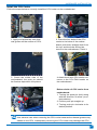
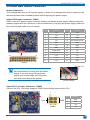
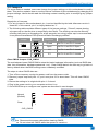
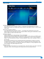
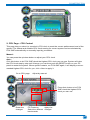
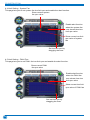
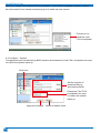
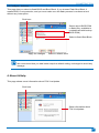
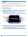
1
H61MXV/H67MXV Series
Motherboard
User’s Manual
Statement:
This manual is the intellectual property of Foxconn, Inc. Although the infor-
mation in this manual may be changed or modified at any time, Foxconn does not obligate itself to inform the user of these changes.
Trademark:
All trademarks are the property of their respective owners.
Version:
User’s Manual V1.3 for H61MXV/H67MXV Series motherboard.
Symbol description:
Note:
Refers to important information that can help you to use motherboard better, and tells you how to avoid problems.
CA
UT
IO
N
Caution:
Indicating a potential risk of hardware damage or physical injury may exist.
WEEE:
The use of this symbol indicates that this product may not be treated as household waste. By ensuring this product is disposed of correctly, you
will help prevent potential negative consequences for the environment
and human health, which could otherwise be caused by inappropriate waste
handling of this product. For more detailed information about recycling of
this product, please contact your local city office, your household waste
disposal service or the shop where you purchased this product.
More information:
If you want more information about our products, please visit:
http://www.foxconnchannel.com
© All rights reserved.
All trade names are registered trademarks of respective manufacturers listed.
All images are for reference only, please refer to the physical motherboard for specific features.
Declaration of conformity
HON HAI PRECISION INDUSTRY COMPANY LTD
66 , CHUNG SHAN RD., TU-CHENG INDUSTRIAL DISTRICT,
TAIPEI HSIEN, TAIWAN, R.O.C.
declares that the product
Motherboard H61MXV/H67MXV Series
is in conformity with
(reference to the specification under which conformity is declared in
accordance with 89/336 EEC-EMC Directive)
■ EN 55022: 1998/A2: 2003 Limits and methods of measurements of radio disturbance characteristics of information technology equipment
■ EN 61000-3-2/:2000 Electromagnetic compatibility (EMC)
Part 3: Limits
Section 2: Limits for harmonic current emissions
(equipment input current <= 16A per phase)
■ EN 61000-3-3/A1:2001 Electromagnetic compatibility (EMC)
Part 3: Limits
Section 2: Limits of voltage fluctuations and flicker in low voltage supply systems for equipment with rated current <= 16A
■ EN 55024/A2:2003 Information technology equipment-Immunity characteristics limits and methods of measurement
Signature : Printed Name : James Liang Place / Date : TAIPEI/2012
Declaration of conformity
Trade Name:
Model Name:
Responsible Party:
Address:
Telephone:
Facsimile:
Equipment Classification:
Type of Product:
Manufacturer:
Address:
FOXCONN
H61MXV/H67MXV Series
PCE Industry Inc.
458 E. Lambert Rd.
Fullerton, CA 92835
714-738-8868
714-738-8838
FCC Class B Subassembly
Motherboard
HON HAI PRECISION INDUSTRY
COMPANY LTD
66 , CHUNG SHAN RD., TU-CHENG
INDUSTRIAL DISTRICT, TAIPEI HSIEN, TAIWAN, R.O.C.
Supplementary Information:
This device complies with Part 15 of the FCC Rules. Operation is subject to the following two
conditions : (1) this device may not cause harmful interference, and (2) this device must accept
any interference received, including interference that may cause undesired operation.
Tested to comply with FCC standards.
Signature : Date : 2012
CA
UT
IO
N
Installation Precautions
■
■
Electrostatic discharge (ESD) is the sudden and momentary electric current that flows between two objects at different electrical potentials. Normally it comes out as a spark which will quickly damage your electronic equipment. Please wear an electrostatic discharge (ESD) wrist strap when handling components such as a motherboard, CPU or memory.
Ensure that the DC power supply is turned off before installing or removing CPU, memory, expansion cards or other peripherals. It is recommended to unplug the AC power cord from the power supply outlet. Failure to unplug the power supply cord may result in serious damage to your system.
Please carefully read the following procedures to install your computer :
■ It is suggested to select high-quality, certified fans in order to avoid damage to the motherboard and CPU due to high temperature. Never turn on the computer if the CPU fan is not properly installed.
■ We cannot guarantee that your system can operate normally when your CPU is overclocked. Normal operation depends on the overclocking capacity of your device.
■ If there is any, when connecting USB, audio, 1394a, RS232 COM, IrDA or
SPDIF cables to the internal connectors on the motherboard, make sure their pinouts are matching with the connectors on the motherboard. Incorrect
connections might damage the motherboard.
■ When handling the motherboard, avoid touching any metal leads or connectors.
■ If there is a PCI Express X16 graphics card installed in your system, we
recommend using a 24-pin ATX power supply to get the best performance.
■ Before turning on the power, please make sure the power supply AC input
voltage setting has been configured to the local standard.
■ To prevent damage to the motherboard, do not allow screws to come in contact with the motherboard circuit or its components. Also, make sure there are no leftover screws or metal components placed on the motherboard or within the computer casing.
■ If you are uncertain about any installation steps or have a problem related to the use of the product, please consult a certified computer technician.
Technical Support
Website: http://www.foxconnchannel.com
Support Website: http://www.foxconnsupport.com
Worldwide online contact Support: http://www.foxconnsupport.com/inquiry.aspx
CPU Support List: http://www.foxconnsupport.com/cpusupportlist.aspx
Memory, VGA Compatibility List: http://www.foxconnsupport.com/complist.aspx
Table of Contents
Chapter 1 Product Introduction
1-1 Product Specifications.............................................................................2
1-2 Layout.....................................................................................................4
1-3 Back Panel Connectors...........................................................................5
Chapter 2 Hardware Installation
2-1 Install the CPU and CPU Cooler.............................................................7
Install the CPU...........................................................................................7
Install the CPU Cooler...............................................................................9
2-2 Install the Memory.................................................................................10
Dual Channel Memory Configuration.......................................................10
Installing a Memory.................................................................................. 11
2-3 Install an Expansion Card.....................................................................12
2-4 Install other Internal Connectors...........................................................13
2-5 Jumpers................................................................................................17
Chapter 3 BIOS Setup
Enter BIOS Setup........................................................................................20
F-Center......................................................................................................23
Smart BIOS..............................................................................................23
Fox Intelligent Stepping...........................................................................24
CPU Configuration...................................................................................25
Performance Tuning.................................................................................26
Advanced....................................................................................................29
North Bridge.............................................................................................29
ME Subsystem.........................................................................................30
Onboard Device Configuration.................................................................31
SATA Configuration .................................................................................32
Super IO Configuration............................................................................33
Trusted Computing...................................................................................34
Network Stack..........................................................................................35
Boot.............................................................................................................36
CSM parameters......................................................................................37
Power..........................................................................................................38
Health..........................................................................................................39
Security.......................................................................................................40
Save & Exit..................................................................................................41
Chapter 4 CD Instruction
4-1 Install driver and utility...........................................................................43
1. Install Driver.........................................................................................43
2. Install Utility..........................................................................................44
4-2 FOX ONE..............................................................................................45
1. Main Page............................................................................................46
2. CPU Page - CPU Control.....................................................................49
3. Frequency Page - Frequency Control (Optional).................................52
4. Limit Setting.........................................................................................52
5. Voltage Page - Voltage Control (Optional)...........................................55
6. Fan Page - Fan Control.......................................................................55
4-3 FOX LiveUpdate....................................................................................56
1. Local Update........................................................................................56
2. Online Update......................................................................................58
3. Configure.............................................................................................61
4. About & Help........................................................................................63
4-4 FOX LOGO...........................................................................................64
4-5 FOX DMI...............................................................................................65
4-6 Smart charger.......................................................................................65
Chapter 1 Product Introduction
Thank you for buying Foxconn H61MXV/H67MXV Series
motherboard. Foxconn products are engineered to maximize computing power, providing only what you need for
break-through performance.
This chapter includes the following information:
■ Product Specifications
■ Layout
■ Back Panel Connectors
PRODUCT INTRODUCTION
1-1 Product Specifications
2
CPU
Support Intel® Ivy Bridge/Sandy Bridge LGA1155 Processors
Max processor power up to 95W
For the latest CPU information, please visit:
http://www.foxconnsupport.com/cpusupportlist.aspx
Chipset
Intel® H61(H61MXV/H61MXV-LE)
Intel® H67(H67MXV)
Memory
2 x 240-pin DDR3 DIMMs
Support up to 16GB of system memory
Dual channel DDR3 1600(Ivy Bridge)/1333/1066MHz architecture
Expansion Slots
1 x PCI Express X16 slot
- Support PCI Express Gen2 5GT/S data rate (Sandy Bridge)
- Support PCI Express Gen3 8GT/s data rate (Ivy Bridge)
2 x PCI Express X1 slot
- Support PCI Express Gen2 5GT/S data rate
Storage
Intel® H61 chipset: (H61MXV/H61MXV-LE)
- 4 x SATA 2.0 connectors (3Gb/s data transfer rate)
Intel® H67 chipset: (H67MXV)
- 2 x SATA 2.0 connectors (3Gb/s data transfer rate)
- 2 x SATA 3.0 connectors (6Gb/s data transfer rate)
LAN
Realtek 8111E Gigabit LAN chip
Support 10/100/1000Mbps
Audio
Realtek ALC662 audio chip
- High Definition Audio
- 2/4/5.1-channel
- Support Jack-Sensing function
USB
Support up to 10 x USB 2.0 ports (6 rear panel ports, 2 onboard USB
headers supporting 4 extra ports)
Support USB 2.0 protocol up to 480Mb/s
Internal
Connectors
1 x 24-pin ATX power connector
1 x 4-pin ATX 12V power connector
4 x SATA 2.0 connectors(H61MXV/H61MXV-LE)
2 x SATA 2.0 connectors+2 x SATA 3.0 connectors(H67MXV)
2 x USB 2.0 headers
1 x CPU fan header (4-pin)
1 x System fan header (4-pin)
1 x Front panel header
1 x Front Audio header
1 x CD_IN header
1 x SPDIF_OUT header
1 x INTR header
1 x COM2 header
1 x TPM header
1 x LPT header
PRODUCT INTRODUCTION
1 x Clear CMOS header
1 x ME header
Back Panel
Connectors
1 x PS/2 mouse port
1 x PS/2 keyboard port
1 x VGA port
1 x DVI-D port
6 x USB 2.0 ports
1 x COM port (H61MXV/H67MXV)
1 x RJ-45 LAN port
3 x Audio ports
Hardware Monitor
System voltage detection
CPU/System temperature detection
CPU/System fan speed detection
CPU overheating warning
CPU/System fan speed control
Green Function
Support ACPI (Advanced Configuration and Power Interface)
Support S0 (normal), S1 (power on suspend), S3 (suspend to RAM), S4
(suspend to disk), S5 (soft - off)
Support EuP function
Bundled Software
FOX ONE
FOX LiveUpdate
FOX LOGO
FOX DMI
Smart Charger
Operating System
Support for Microsoft® Windows® 8/7/XP
Form Factor
Micro ATX Form Factor, 9.6 inches x 7.8 inches (24.4cm x 19.8cm)
3
PRODUCT INTRODUCTION
1-2 Layout
6
5
4
3
2
1
7
8
22
9
21
10
11
20
12
19
13
14
15
1. 4-pin ATX 12V Power Connector
2. SYS_FAN1 Header
3. PCI Express X16 Slot
4. Clear CMOS Header
5. PCI Express X1 Slot
6. CD_IN Header
7. Front Audio Header
8. SPDIF_OUT Header
9. Front USB 2.0 Header
10. TPM Header
11. ME Header
12. Front Panel Header
16
17
18
13. SATA 2.0 Connector
14. SATA 2.0 Con nector(H61MXV/H61MXV-LE)
SATA 3.0 Connector(H67MXV)
15. Chipset: Intel® H61(H61MXV/H61MXV-LE)
Chipset: Intel® H67(H67MXV)
16. 24-pin ATX Power Connector
17. LPT Header
18. INTR Header
19. COM2 Header
20. DDR3 DIMM Slot
21. CPU_FAN Header
22. LGA1155 CPU Socket
The above motherboard layout is for reference only, please refer to the physical
motherboard for detail.
4
PRODUCT INTRODUCTION
1-3 Back Panel Connectors
Serial Port (Optional)
PS/2 Mouse Port
5
1
RJ-45 LAN Port
7
Line In
Line Out
Microphone In
2
3
PS/2 Keyboard Port
DVI-D Port
4
6
8
VGA Port
USB 2.0 Ports
Audio Ports
1. PS/2 Mouse Port
Use the upper port to connect a PS/2 mouse.
2. PS/2 Keyboard Port
Use the lower port to connect a PS/2 keyboard.
3. DVI-D Port
The DVI-D port supports DVI-D specification. Connect a monitor that supports DVI-D
connection to this port.
4. VGA Port
To connect with external display devices, such as monitor or LCD display.
5. Serial Port
This is output of RS232 COM1 port.
6. USB 2.0 Ports
The USB port supports the USB 2.0/1.1 specification. Use this port for USB devices such as an USB keyboard/mouse, USB printer, USB flash drive and etc.
7. RJ-45 LAN Port
The Ethernet LAN port provides Internet connection at up to 10/100/1000Mb/s data rate.
LAN Type
Left: Active
Status
Off
1000M
Green
Blinking
Right: Link
Description
No Link
Data
Activity
Status
Description
Off
No Link
Off
10Mb/s Connection
Green
100Mb/s Connection
Orange
1000Mb/s Connection
Active Link
LEDLED
8. Audio Ports
For the definition of each audio port, please refer to the table below :
Port
Blue
Green
Pink
2-channel
4-channel
5.1-channel
Rear Speaker Out*
Line In
Rear Speaker Out*
Line Out
Front Speaker Out
Front Speaker Out
Microphone In
Microphone In
Center/Subwoofer Out*
* : Please refer to Chapter 4, and install the Realtek audio driver (in CD) to assign the audio
output ports for different applications of 2/4/5.1 channels. The fundamental audio outputs are
depicted in the table above.
5
Chapter 2
Hardware Installation
This chapter introduces the hardware installation process, including the installation of the CPU, memory, power supply, slots, pin headers and the mounting of clear
CMOS. Caution should be exercised during the installation of these modules. Please refer to the motherboard
layout prior to any installation and read the contents in
this chapter carefully.
This chapter includes the following information :
■ Install the CPU and CPU Cooler
■ Install the Memory
■ Install an Expansion Card
■ Install other Internal Connectors
■ Jumpers
HARDWARE INSTALLATION
2-1 Install the CPU and CPU Cooler
Read the following guidelines before you begin to install the CPU :
■ Make sure that the motherboard supports the CPU.
■ Always turn off the computer and unplug the power cord from the power supply before installing the CPU to prevent hardware damage.
■ Locate the pin one of the CPU. The CPU cannot be inserted if oriented
incorrectly. (Or you may locate the notches on both sides of the CPU and
alignment keys on the CPU socket.)
■ Apply an even and thin layer of thermal grease on the surface of the CPU.
■ Do not turn on the computer if the CPU cooler is not installed, otherwise
overheating and damage of the CPU may occur.
■ Set the CPU host frequency in accordance with the CPU specifications. It is not recommended that the system bus frequency be set beyond hardware
specifications since it does not meet the standard requirements for the
peripherals. If you wish to set the frequency beyond the standard specifications, please do so according to your hardware specifications including the CPU, graphics card, memory, hard drive, etc.
Hyper-Threading Technology System Requirements:
(Go to Intel's website for more information about the Hyper-Threading Technology)
■ An Intel® CPU that supports HT Technology
■ A chipset that supports HT Technology
■ An operating system that is optimized for HT Technology
■ A BIOS that supports HT Technology and has it enabled
Install the CPU
Locate the alignment keys on the motherboard CPU socket and the notches on the CPU.
LGA1155 CPU Socket
Alignment Key
Pin-1 corner of
the CPU Socket
LGA1155 CPU
Notch
Pin-1 triangle
marking of CPU
7
HARDWARE INSTALLATION
Follow the steps to install the CPU onto the CPU socket :
Before installing the CPU, make sure to turn off the computer and unplug the power
cord from the power outlet to prevent damage to the CPU.
1. Release the CPU socket lever.
2. Lift the metal cover on the CPU
socket.
3. Remove protective socket cover.
4. Check pin one marking (triangle)
with the pin one corner of the CPU
socket, align the CPU notches with
the socket alignment keys and gently
put the CPU onto the socket.
5. When CPU is properly seated, replace the metal cover and push the
CPU socket lever back to its locked
position.
8
HARDWARE INSTALLATION
Install the CPU Cooler
Follow the steps below to correctly install the CPU cooler on the motherboard.
1. Apply and spread an even thermal grease on the surface of CPU.
2. Place the four bolts of the CPU
cooler to the holes of the motherboard, push them straight down from
the top, and the bolts will be fastened on the motherboard. That's it.
3. Check the solder side of the
motherboard, the push pin should
be fixed as depicted in the picture.
4. Attach the 4-wire CPU cooler connector to the CPU FAN header on
the motherboard .
3
2
1
Release bolts of CPU cooler from
motherboard :
1. Turning the push pin (bolt) along
with the direction of arrow (counterclockwise).
2. Pull the push pin straight up.
3. Turning push pin clockwise to its
default position.
Use extreme care when removing the CPU cooler because the thermal grease may
adhere to the CPU. Inadequately removing the CPU cooler may damage the CPU.
9
HARDWARE INSTALLATION
2-2 Install the Memory
Read the following guidelines before you begin to install the memory :
■ Make sure that the motherboard supports the memory. It is recommended that memory of the same capacity, brand, speed, and chips be used, and please select Dual channel first to achieve optimum performance.
■ Always turn off the computer and unplug the power cord from the power outlet before installing the memory to prevent hardware damage.
■ Memory modules have a foolproof design. A memory module can be installed in only one direction. If you are unable to insert the memory, switch the direction.
Dual Channel Memory Configuration
Channel 0 : DIMM1, Channel 1 : DIMM2,
The combinations of DIMM modules are :
DIMM1
DIMM2
DS/SS
-
Single Channel
-
DS/SS
Dual Channel
DS/SS
DS/SS
Single Channel
(DS : Double Side, SS : Single Side, - : No Memory)
10
HARDWARE INSTALLATION
Installing a Memory
96-Pin
144-Pin
If you take a look at front side of memory module, it has asymmetric pin counts on both sides
separated by a notch in the middle, so it can only fit in one direction. Follow the steps below to
correctly install your memory modules into the sockets.
Notch
Step 1:
Spread the clips at both ends of the memory socket. Place the memory module onto the socket, then
put your fingers on top edge of the module, and
push it down firmly and seat it vertically into the
memory socket.
Step 2:
The clips at both ends of the socket will snap into
place when the memory module is securely inserted.
11
HARDWARE INSTALLATION
2-3 Install an Expansion Card
■ Make sure the motherboard supports the expansion card.
■ Always turn off the computer and unplug the power cord from the power outlet
before installing an expansion card to prevent hardware damage.
PCI Express X16
PCI Express X1
Follow the steps below to correctly install your expansion card in the expansion slot.
1. Locate an expansion slot that supports your card. Remove the metal slot cover from the
chassis back panel.
2. Align the card with the slot, and press down on the card until it is fully seated in the slot.
3. Make sure the metal contacts on the card are completely inserted into the slot.
4. Secure the card's metal bracket to the chassis back panel with a screw.
5. After installing all expansion cards, replace the chassis cover.
6. Turn on your computer. If necessary, go to BIOS Setup to make any required BIOS changes for your expansion card(s).
7. Install the driver provided with the expansion card in your operating system.
Installing and Removing a PCI Express X16 Graphics Card :
• Installing a Graphics Card:
Gently insert the graphics card into the PCI Express X16 slot.
Make sure the graphics card is locked by the latch at the end
of the PCI Express X16 slot.
• Removing the Card:
Push the latch at the end of the PCI Express X16 slot to release the card and then pull the card straight up from the slot.
12
HARDWARE INSTALLATION
2-4 Install other Internal Connectors
Power Connectors
This motherboard uses an ATX power supply. In order not to damage any device, make sure all
the devices have been installed properly before applying the power supply.
24-pin ATX Power Connector : PWR1
PWR1 is the ATX power supply connector. Make sure that the power supply cable and pins are
properly aligned with the connector on the motherboard. Firmly plug the power supply cable into
the connector and make sure it is secure.
24
12
13
PWR1
1
Pin #
Definition
Pin #
1
3.3V
13
Definition
3.3V
2
3.3V
14
-12V
3
GND
15
GND
4
+5V
16
PS_ON(Soft On/Off)
5
GND
17
GND
6
+5V
18
GND
7
GND
19
GND
8
Power Good
20
NC
9
+5V SB(Stand by +5V)
21
+5V
10
+12V
22
+5V
11
+12V
23
+5V
12
3.3V
24
GND
Pin No. 24
We recommend you using a 24-pin power
supply. If you are using a 20-pin power
supply, you need to align the ATX power
connector according to the picture.
20-Pin Power
4-pin ATX 12 V Power Connector : PWR2
Connect the ATX 12V power supply to PWR2 and provides power to the CPU.
3
1
+12V
GND
Pin #
Definition
1
GND
2
GND
4 2
3
+12V
PWR2
4
+12V
13
HARDWARE INSTALLATION
CD_IN Header: CD_IN
CD_IN is a Sony standard audio connector, it can be
connected to a CD/DVD-ROM drive through a CD/
DVD audio cable.
CD_L GND CD_R
1
CD_IN
Audio Header: F_AUDIO
The audio header supports HD Audio standard. It
provides the Front Audio output choice.
A_MIC2_L
A_MIC2_R
A_LINE2_R
SENSE_SEND
A_LINE2_L
1 2
9 10
AUD_GND
PRESENCEJ
SENSE1_RETURN
EMPTY
SENSE2_RETURN
F_AUDIO
USB Headers : F_USB1/2
In addition to the USB ports on the rear panel, this
product also provides 10-pin USB headers on its
motherboard. By connecting through USB cables
with them, user can quickly expand another USB
ports on the front panel.
VCC
DD+
GND
EMPTY
1 2
9 10
F_USB1/2
VCC
DD+
GND
GND
1
GND
TX+
TXGND
RXRX+
GND
Serial ATA 2.0 Connectors: SATA_1/2/3/4
These connectors are used to connect with
SATA 2.0 Hard Disk drives or optical disk devices.
Serial ATA 3.0 Connectors: SATA_1/2(H67MXV)
These connectors are used to connect with
SATA 3.0 Hard Disk drives.
Chassis Intrusion Alarm Header : INTR
The header can be connected to a security switch on
the chassis. The system can detect the chassis intrusion through the function of this connector. If eventually the chassis is closed, the system will send a
message out.
14
SATA_1/2/3/4
1
GND
TX+
TXGND
RXRX+
GND
SATA_1/2
INTRUDERJ
1
GND
INTR
HARDWARE INSTALLATION
Front Panel Header: FP1
This motherboard includes one header for connecting the
front panel switch and LED Indicators.
Hard Disk LED Header(HDD-LED)
Connect to the chassis front panel IDE indicator LED.
It indicates the active status of the hard disks. This
2-pin header is directional with +/- sign.
HDD-LED
+
1
2
-
+
PWR-LED
-
RESET-SW
NC
PWR-SW
9 10
FP1
EMPTY
Reset Switch (RESET-SW)
Attach the header to the Reset switch on the front
panel of the case; the system will restart when the
switch is pressed.
Power LED Header(PWR-LED)
Connect to the power LED indicator on the front panel
of the chassis. The Power LED indicates the system’s
status. When the system is in operation (S0 status),
the LED is on. When the system gets into sleep mode
(S1) , the LED is blinking; When the system is in S3/
S4 sleep state or power off mode (S5), the LED is off.
This 2-pin header is directional with +/- sign.
Power Switch Header(PWR-SW)
Connect to the power button on the front panel of
the chassis. Push this switch allows the system to be
turned on and off rather than using the power supply
button.
COM Header: COM2
This motherboard supports one serial RS232 COM port
for legacy compatibility. User must purchase another
RS232 cable with a 9-pin D-sub connector at one end
to connect with the external RS232 device and another
end with 10-pin female connector to connect with COM1
header in the motherboard.
SPDIF OUT Header: SPDIF_OUT
The header is used for SPDIF output.
DCD
SOUT
GND
RTS
RI
1
1 2
9 10
COM2
SIN
DTR
DSR
CTS
EMPTY
+5V
EMPTY
SPDIF_OUT
GND
SPDIF_OUT
15
HARDWARE INSTALLATION
TPM Header: TPM
The TPM (Trusted Platform Module) provides the ability
to the PC to run applications more secure and to make
transactions and communication more trustworthy. To
utilize this function, you should purchase additional
device and install it.
LCLK
LFRAMEn
LRESETn
LAD3
VDD
LAD0
NC_1
NC_2
GND
LPCPDn
1 2
19 20
GND
EMPTY
NC_3
LAD2
LAD1
GND
NC_4
SERIRQ
CLKRUNin
NC_5
TPM
Fan Headers : CPU_FAN, SYS_FAN1
There are two main fan headers on this motherboard.
The fan speed can be controlled and monitored in
“Health” section of the BIOS Setup. These fans can be
automatically turned off after the system enter S3, S4
and S5 sleeping states.
1
GND
POWER
SENSE
CONTROL
CPU_FAN/SYS_FAN1
LPT Header: LPT
The header supports parallel port which can be connected to a printer or a scanner. System usually assign
IRQ7 as it’s default interrupt request and the parallel
port has three operation mode: [SPP], [EPP], [ECP].
Strobe
Data it [0]
Data it [1]
Data it [2]
Data it [3]
Data it [4]
Data it [5]
Data it [6]
Data it [7]
ACK
Busy
Paper End
Select
1 2
25 26
LPT
16
Auto Feed
Error
INIT
SLCT IN
Ground
Ground
Ground
Ground
Ground
Ground
Ground
Ground
Empty
HARDWARE INSTALLATION
2-5 Jumpers
For some features needed, users can change the jumper settings on this motherboard to modify
them. This section explains how to use the various functions of this motherboard by changing the
jumper settings. Users should read the following content carefully prior to modifying any jumper
setting.
Description of Jumpers
1. For any jumper on this motherboard, pin 1 can be identified by the bold silkscreen next to it.
However, in this manual, pin 1 is simply labeled as “1”.
2. The following table explains different types of the jumper settings. "Closed" means placing
a jumper cap on the two pins to temporarily short them. The shorting can also be done by
touching two pins by a screwdriver for a few seconds, but using jumper cap is recommended.
It can prevent hazardous ESD (Electrical Static Discharge) problem.
Jumper
Diagram
Definition
Description
1
Closed
Set Pin 1 and Pin 2 closed
1
Open
Set Pin 1 and Pin 2 Open
1
1-2
Set Pin 1 and Pin 2 closed
1
2-3
Set Pin 2 and Pin 3 closed
1
1
Clear CMOS Jumper: CLR_CMOS
The motherboard uses CMOS RAM to store the basic hardware information (such as BIOS data,
date, time information, hardware password...etc.). Clear CMOS data is the fast way to go back to
factory default when the BIOS settings were mistakenly modified.
The steps to clear CMOS data are :
1. Turn off the computer, unplug the power cord from the power outlet.
2. Remove jumper cap from pins 1-2, put it onto pins 2-3 to short them. This will clear CMOS data.
3. Return the setting to its original with pins 1-2 closed.
4. Plug in the power cord to your computer and turn it on.
5. Go to BIOS Setup to configure new system as described in next chapter.
Normal
(Default)
Clear
1
2
3
1
2
3
CA
UT
IO
N
CLR_CMOS
■ Disconnect the power cable before clearing CMOS.
■ Do not clear the CMOS while the system is turned on.
17
HARDWARE INSTALLATION
Intel® ME Jumper: PCH_ME_ENABLE
This motherboard uses PCH_ME_ENABLE jumper to enable or disable Intel® Management
Engine function.
Intel® Management Engine (ME) is an embedded microcontroller located in Intel chipset. It provides latest IT management features such as Intel® AMT, that allows to improve management of
corporate assets.
Set the jumper to pins 1-2, you can enable the Intel® Management Engine function.
Set the jumper to pins 2-3, you can disable the Intel® Management Engine function.
Enable
(Default)
Disable
1
2
3
1
2
3
CA
UT
IO
N
PCH_ME_ENABLE
18
Before flashing BIOS ROM, you need to set PCH_ME_ENABLE jumper to pins 2-3 first. Chapter 3
BIOS Setup
This chapter tells how to change system settings through
the BIOS Setup menus. Detailed descriptions of the
BIOS parameters are also provided.
You have to run the Setup Program when the following
cases occur:
1. An error message appears on the screen during the
system Power On Self Test (POST) process.
2. You want to change the default CMOS settings.
This chapter includes the following information :
■ Enter BIOS Setup
■ Main
■ F-Center
■ Advanced
■ Boot
■ Power
■ Health
■ Security
■ Save & Exit
BIOS SETUP
Enter BIOS Setup
The BIOS is the communication bridge between hardware and software, correctly setting up the
BIOS parameters is critical to maintain optimal system performance. Power on the computer,
when the message "Press <DEL> to enter Setup, <F7> to Boot Menu" appears at the bottom
of the screen, you can press <DEL> key to enter Setup.
We do not suggest that you change the default values in the BIOS Setup, and we
shall not be responsible for any damage which resulted from the change you made.
Use the arrow right/left keys or click the menu tag to select a specific function and go to the
submenu. Each function is explained below:
Main It displays the basic system configuration, such as CPU Name, memory size, system date, time
and so on. They all can be viewed or set up through this menu.
F-Center
The advanced system features can be set up through this menu.
Advanced
The values for the chipset can be changed through this menu, and the system performance can
be optimized.
Boot
Boot features can be set up through this menu. You can set the boot device priority here.
Power
All the items related with Green function features can be setup through this menu.
Health
This setup enables you to read/change fan speeds, and displays temperatures and voltages of
your CPU/System.
Security
The Administrator/User password can be set up through this menu to prevent unauthorized
use of your computer. If you set a password, the system will ask you to key in correct password
before boot or access to Setup.
Save&Exit
The optimal performance settings can be loaded through this menu. However, it may offer better performance in some ways (such as less I/O cards, less memory ...etc.), still, it may cause
problem if you have more memory or I/O cards installed. It means, if your system loading is
heavy, set to optimal default may sometimes come out an unstable system. What you need now
is to adjust BIOS setting one by one, trial and error, to find out the best setting for your current
system. You also can save or discard the changes and exit BIOS setup here.
20
BIOS SETUP
Main
Main
F-center
Advanced
Boot
Power
Health
Security
System Date
System Time
[Wed 09/18/2012]
[09:35:03]
Access Level
Model Name
ME Version
BIOS Version
Build Date and Time
Administrator
H61MXV/H61MXV-LE/H67MX
8.1.0.1248
C12F1D04
09/13/2012 15:51:02
Halt On
CPU Brand Name:
Genuine Intel(R) CPU @ 3.00GHz
Total Memory MAC Address
Save&Exit
Set the Date. Use Tab to
switch between Date
elements.
[All, but keyboard]
2048 MB (DDR3 1333)
D0-27-88-A5-97-7B
→ ←: Select Screen
↑ ↓/Click: Select Item
Enter/Dbl Click: Select
+/-: Change Opt.
F1: General Help
F2: Previous Values
F3: Optimized Defaults
F4: Save & Exit
ESC/Right Click: Exit
Version 2.14.1219. Copyright (C) 2012 American Megatrends, Inc.
► System Date
<weekday><month><date> <year> format.
Day—weekday from Sun. to Sat., this message is automatically displayed by BIOS (Read
Only).
Month—month from 1 to 12.
Date—date from 1 to 31.
Year—year, set up by users.
Use [ENTER], [TAB] or [SHIFT-TAB] to select a field. Use [+] or [-] to input the value.
► System Time
This item allows you to configure the desired time. Use [ENTER], [TAB] or [SHIFT-TAB] to
select a field. Use [+] or [-] to input the value.
The three fields of the setting are <hour> : <minute> : <second> respectively.
► Access Level
It displays your current access level. If you enter system with a user password, it will display
“User”. If no password is set or you enter system with administrator password, this item will
display “Administrator”.
► Model Name
This item shows the model name of this product.
► ME Version
It displays the current ME version.
► BIOS Version
It displays the current BIOS version. User can check this information and discuss with the
field service people if a BIOS upgrade is needed.
► Build Date and Time
This item shows the BIOS building date and time.
► Halt On
This category determines whether or not the computer will stop if an error is detected during
powering up.
[All Errors]: All errors can result in system halt.
21
BIOS SETUP
[No Errors]: No error can result in system halt.
[All, but keyboard]: All errors but keyboard can result in system halt.
► CPU Brand Name
It displays the current CPU name.
► Total Memory
This item displays the total memory size. The size is depending on how many memory modules are installed in your system before powering on.
► MAC Address
This item displays the onboard LAN MAC address.
22
BIOS SETUP
F-Center
Main
F-center
Advanced
Boot
Power
Health
Security
Fox Control Center
Super BIOS Protect
▶
▶
▶
▶
Save&Exit
Super BIOS Protection
Settings
[Enabled]
Smart BIOS
Fox Intelligent Stepping
CPU Configuration
Performance Tuning
→ ←: Select Screen
↑ ↓/Click: Select Item
Enter/Dbl Click: Select
+/-: Change Opt.
F1: General Help
F2: Previous Values
F3: Optimized Defaults
F4: Save & Exit
ESC/Right Click: Exit
Version 2.14.1219. Copyright (C) 2012 American Megatrends, Inc.
► Super BIOS Protect
To protect the system BIOS, there is a BIOS write-protection mechanism provided to prevent
BIOS FLASH tool being improperly used to update BIOS or the vicious virus(such as CHI,
etc.) rewriting BIOS setup.
► Smart BIOS/Fox Intelligent Stepping/CPU Configuration/Performance Tuning
Press <Enter> to go to relative submenu.
Smart BIOS
Main
F-center
Advanced
Boot
Power
Smart BIOS
Smart Power LED
Smart Boot Menu
Health
Security
Save&Exit
Smart Power LED Settings
[Disabled]
[Enabled]
→ ←: Select Screen
↑ ↓/Click: Select Item
Enter/Dbl Click: Select
+/-: Change Opt.
F1: General Help
F2: Previous Values
F3: Optimized Defaults
F4: Save & Exit
ESC/Right Click: Exit
Version 2.14.1219. Copyright (C) 2012 American Megatrends, Inc.
23
BIOS SETUP
► Smart Power LED
Smart Power LED is a feature built on your motherboard to indicate different states during
Power-On Self-Test (POST). The LED is located at the front panel, and it displays POST
state by different long-short blinking intervals. You can always leave this state enabled.
►Smart Boot Menu
When PC starts, it will ask you to press [Del] key to enter setup or press [F7] key to enter
smart boot menu. If [Disabled] is selected, then pressing [F7] has no function. This also prevents user without password trying to get into your computer through smart boot menu.
Fox Intelligent Stepping
Main
F-center
Spread Spectrum
Advanced
Boot
Power
Health
[Enabled]
Security
Save&Exit
Spread Spectrum Settings
→ ←: Select Screen
↑ ↓/Click: Select Item
Enter/Dbl Click: Select
+/-: Change Opt.
F1: General Help
F2: Previous Values
F3: Optimized Defaults
F4: Save & Exit
ESC/Right Click: Exit
Version 2.14.1219. Copyright (C) 2012 American Megatrends, Inc.
► Spread Spectrum
If you enabled this function, it can significantly reduce the EMI (Electromagnetic Interference)
generated by the system, so to comply with FCC regulation. But if overclocking is activated,
you had better disable it.
24
BIOS SETUP
CPU Configuration
Main
F-center
Advanced
Boot
Power
Health
Security
Save&Exit
Intel AES-NI
CPU Configuration
CPU Brand Name:
Intel(R) CPU @ 3.00GHz
L1 Data Cache
L1 Code Cache
L2 Cache
L3 Cache
Processor Stepping
Max CPU Speed
Min CPU Speed
CPU Speed
Processor Cores
Intel HT Technolony
Intel VT-x Technolony
Intel SMX Technolony
32 KB x 4
32 KB x 4
256 KB x 4
6144 KB
6
3000 MHz
1600 MHz
3000 MHz
4
Not Supported
Supported
Not Supported
Intel AES-NI
Intel XD Bit
Limit CPUID Maximum
Intel Virtualization Technolony
CPU C3 Report
CPU C6 Report
[Enabled]
[Enabled]
[Disabled]
[Disabled]
[Enabled]
[Enabled]
→ ←: Select Screen
↑ ↓/Click: Select Item
Enter/Dbl Click: Select
+/-: Change Opt.
F1: General Help
F2: Previous Values
F3: Optimized Defaults
F4: Save & Exit
ESC/Right Click: Exit
Version 2.14.1219. Copyright (C) 2012 American Megatrends, Inc.
► Intel AES-NI
This item is used to disable or enable Advanced Encryption Standard feature.
► Intel XD Bit
This item is used to enable/disable the Execute Disable Bit feature.
Intel’s Execute Disable Bit functionality can help prevent certain classes of malicious buffer
overflow attacks when combined with a supporting operating system.
► Limit CPUID Maximum
This item is used to enable or disable CPUID maximum value limit configuration.
Set [Enabled] : the maximum CPUID is 3.Set [Disabled] for WinXP.
► Intel Virtualization Technology (Appears only when CPU supports)
Virtualization (i.e. Intel® Vanderpool Technology) allows a platform to run multiple operating
systems and applications in independent partitions or “containers.” One physical computer
system can function as multiple “virtual” systems. Vanderpool Technology can help improve
future virtualization solutions. This item will be displayed only when the CPU is supporting
this feature and the setting is used to enable or disable it.
► CPU C3 Report
This item is used to enable or disable CPU C3 (ACPI C2) report to OS.
► CPU C6 Report
This item is used to enable or disable CPU C6 (ACPI C3) report to OS.
► Hyper-Threading (Appears only when CPU supports)
This item is used to enable or disable the Hyper-Threading Technology feature.
25
BIOS SETUP
Performance Tuning
Main
F-center
Advanced
Boot
Power
Health
Security
▶CPU Configuration
▶North Bridge Configuration
Save&Exit
CPU Configuration
→ ←: Select Screen
↑ ↓/Click: Select Item
Enter/Dbl Click: Select
+/-: Change Opt.
F1: General Help
F2: Previous Values
F3: Optimized Defaults
F4: Save & Exit
ESC/Right Click: Exit
Version 2.14.1219. Copyright (C) 2012 American Megatrends, Inc.
► CPU Configuration/North Bridge Configuration
Press <Enter> to go to relative submenu.
CPU Configuration
Main
EIST
Turbo Mode
F-center
Advanced
Boot
Power
[Enabled]
[Enabled]
Health
Security
Save&Exit
Enhanced Intel SpeedStep
Technology
→ ←: Select Screen
↑ ↓/Click: Select Item
Enter/Dbl Click: Select
+/-: Change Opt.
F1: General Help
F2: Previous Values
F3: Optimized Defaults
F4: Save & Exit
ESC/Right Click: Exit
Version 2.14.1219. Copyright (C) 2012 American Megatrends, Inc.
► EIST
You can enable or disable the EIST (Processor Power Management, PPM) through this item.
26
CA
UT
IO
N
BIOS SETUP
Enhanced Intel SpeedStep® technology (EIST) allows the system to dynamically
adjust processor voltage and core frequency, which can result in decreased average
power consumption and decreased average heat production. There are some
system requirements must be met, including CPU, chipset, motherboard, BIOS and
operation system. Please refer to Intel Website for more information.
►Turbo Mode
Turbo mode allows processor cores to run faster than its marked frequency in specific condition.
North Bridge Configuration
Main
F-center
Advanced
Boot
Power
Health
Memory Multiplier Configuration
Performance Memory Profiles
XMP Profile 1
XMP Profile 2
[Automatic]
Not Supported
Not Supported
Security
Save&Exit
The selection of
Performance Memory
Profiles which impacts
memory sizing behavior.
Intel Graphics Configuration
Graphics Core Ratio Limit
Graphics Voltage(1/256)
21
0
→ ←: Select Screen
↑ ↓/Click: Select Item
Enter/Dbl Click: Select
+/-: Change Opt.
F1: General Help
F2: Previous Values
F3: Optimized Defaults
F4: Save & Exit
ESC/Right Click: Exit
Version 2.14.1219. Copyright (C) 2012 American Megatrends, Inc.
► Performance Memory Profiles
This item is used to select performance memory profile.
Options:[Automatic], [Manual], [XMP Profile 1], [XMP Profile 2].
[Automatic]- Configuration database of using performance memory profile.
[Manual]- Configuration database of using performance memory profile. The next submenu
will appear when select this item.
[XMP Profile 1]-Configuration database of using XMP timing profile 1.
[XMP Profile 2]- Configuration database of using XMP timing profile 2.
The following items appear only when the option is set to “Manual”.
► Memory Clock Multiplier
This item is used to set the memory clock multiplier.
► Memory Multiplier
This item is used to set the memory multiplier.
► tCL
The number of memory clocks it takes a DRAM to return data after the read CAS_L is asserted depends on the memory clock frequency. The value that BIOS programs into the memory
controller is a function of the target clock frequency. The target clock frequency is determined
27
BIOS SETUP
from the supported CAS latencies at given clock frequencies of each DIMM.
► tRP
This item allows you to select the row precharge time (in clock cycles).
► tRCD
This item allows you to select a delay time (in clock cycles) between the CAS# and RAS#
strobe signals.
► tRAS
This item allows you to set the minimum RAS# active time (in clock cycles).
► tWR
This item allows you to select the write recovery time (in clock cycles).
► tRFC
Refresh to Refresh or Refresh to Active command interval.
► tWTR
This item allows you to select a delay time (in clock cycles) between sending the last data
from a write operation to the memory and issuing a read command.
► tRRD
This item allows you to select a delay time (in clock cycles) between the RAS# and RAS#
strobe signals.
► tRTP
Internal READ Command to PRECHARGE Command delay
► tFAW
This item allows you to specify the time window in which four activates are allowed the same
rank.
► Graphics Core Ratio Limit
This item is used to set the graphics care ratio limit.
► Graphics Voltage(1/256)
This item is used to set the graphics voltage.
28
BIOS SETUP
Advanced
Main
▶
▶
▶
▶
▶
▶
▶
F-center
Advanced
Boot
Power
Health
Security
North Bridge
ME Subsystem
Onboard Device Configuration
SATA Configuration
Super IO Configuration
Trusted Computing
Network Stack
Save&Exit
North Brigde Parameters
→ ←: Select Screen
↑ ↓/Click: Select Item
Enter/Dbl Click: Select
+/-: Change Opt.
F1: General Help
F2: Previous Values
F3: Optimized Defaults
F4: Save & Exit
ESC/Right Click: Exit
Version 2.14.1219. Copyright (C) 2012 American Megatrends, Inc.
►North Bridge/ME Subsystem/Onboard Device Configuration/SATA Configuration/Super IO
Configuration/Trusted Computing/Network Stack
Press <Enter> to go to relative submenu.
North Bridge
Main
F-center
Advanced
Boot
Power
Health
Security
North Bridge Configuration
Memory Information Total Memory
2048 MB (DDR3 1333)
Memory Slot1
Not Present
Memory Slot2
2048 MB (DDR3 1333)
Memory Configuration
Integrated Graphics
UMA Frame buffer Size
Initate Graphic Adapter
VT-d
IGD Multi-Monitor
DVMI/FIXED Memory
Save&Exit
Keep IGD enabled based on
the setup options.
[Auto]
[256M]
[Auto]
[Disabled]
[Disabled]
[256MB]
→ ←: Select Screen
↑ ↓/Click: Select Item
Enter/Dbl Click: Select
+/-: Change Opt.
F1: General Help
F2: Previous Values
F3: Optimized Defaults
F4: Save & Exit
ESC/Right Click: Exit
Version 2.14.1219. Copyright (C) 2012 American Megatrends, Inc.
► Total Memory
This item displays the current using memory information.
► Memory Slot 1/2
These items display the memory size installed on each slot.
► Integrated Graphics
29
BIOS SETUP
This item is used to set the mode of the Integrated Graphics.
►UMA Frame buffer Size
Allocates system memory for use as video memory to ensure the most efficient use of available resources for maximum 2D/3D graphics performance.
This is a memory allocation method addition to the Unified Memory Architecture (UMA)
concept, wherein a static amount of page-locked graphics memory is allocated during driver
initialization. This fixed amount of memory will provide the user with a guaranteed graphics
memory at all times, and will no longer be available to the OS.
► Initial Graphic Adapter
This item is used to select which graphics controller is used as the primary boot device.
► VT-d
This item is used to enable or disable the VT-d feature. Intel® Virtualization Technology for
Directed I/O (VT-d) can help end users improve security and reliability of the systems and
also improve performance of I/O devices in virtualized environment. ► IGD Multi-Monitor
This item is used to enable or disable the IGD Multi-Monitor by internal graphics device.
► DVMT/FIXED Memory
This item is used to select DVMT/FIXED Memory size used by Internal Graphics Device.
ME Subsystem
Main
F-center
Advanced
Boot
Power
Health
Security
Save&Exit
Intel ME Subsystem Configuration
ME Version
8.1.0.1248 → ←: Select Screen
↑ ↓/Click: Select Item
Enter/Dbl Click: Select
+/-: Change Opt.
F1: General Help
F2: Previous Values
F3: Optimized Defaults
F4: Save & Exit
ESC/Right Click: Exit
Version 2.14.1219. Copyright (C) 2012 American Megatrends, Inc.
► ME firmware Version
It displays the current ME version.
30
BIOS SETUP
Onboard Device Configuration
Main
F-center
Advanced
Boot
Power
Onboard Device Configuration
Onboard LAN Controller
Onboard LAN PXE OpROM
Onboard USB Controller
Legacy USB Support
Azalia HD Audio Controller
[Enabled]
[Disabled]
[Enabled]
[Enabled]
[Enabled]
Health
Security
Save&Exit
Enable/Disable Onboard
LAN Controller.
→ ←: Select Screen
↑ ↓/Click: Select Item
Enter/Dbl Click: Select
+/-: Change Opt.
F1: General Help
F2: Previous Values
F3: Optimized Defaults
F4: Save & Exit
ESC/Right Click: Exit
Version 2.14.1219. Copyright (C) 2012 American Megatrends, Inc.
► Onboard LAN Controller
This item is used to enable or disable the onboard LAN controller.
► Onboard LAN PXE OpROM
This item is used to enable or disable onboard LAN PXE option ROM.
► Onboard USB Controller
This item is used to enable or disable the onboard USB controller.
► Legacy USB Support
This item is used to enable the support for USB devices on legacy OS. If you have a USB
keyboard or mouse, set to auto or enabled.
[Enabled]: This option will enable the legacy USB support.
[Disabled]: This option will keep USB devices available only for EFI applications.
[Auto]: This option will disable the legacy support if no USB devices are connected.
► Azalia HD Audio Controller
This item is enable or disable the Azalia HD Audio Controller.
31
BIOS SETUP
SATA Configuration
Main
F-center
Advanced
Boot
Power
Health
SATA Configuration
SATA Controller(s)
Onboard SATA Mode
▶SATA Port1: Not Present
▶SATA Port2: Not Present
▶SATA Port3: Not Present
▶SATA Port4: Not Present
[Enabled]
[Native IDE]
Security
Save&Exit
Enable or disable SATA
Device.
→ ←: Select Screen
↑ ↓/Click: Select Item
Enter/Dbl Click: Select
+/-: Change Opt.
F1: General Help
F2: Previous Values
F3: Optimized Defaults
F4: Save & Exit
ESC/Right Click: Exit
Version 2.14.1219. Copyright (C) 2012 American Megatrends, Inc.
► SATA Controller(s)
This item is used to enable or disable the onboard SATA controller.
► Onboard SATA Mode
This item is used to set the operating mode of your SATA ports.
[Native IDE] - This configures the SATA ports to support native IDE mode.
[AHCI] - The Advanced Host Controller Interface (AHCI) specification describes the register
level interface for a Host Controller for Serial ATA. The specification includes a description of
the hardware/software interface between system software and the host controller hardware.
AHCI provides more advanced features including SATA features, but some SATA drives may
not support AHCI, unless they are labeled with AHCI support in its specification.
If your motherboard supporting AHCI, and you have a SATA device, which also supports
AHCI, then you can select IDE option to have fair performance (only PATA, SATA level), or
you can select AHCI to get its best performance.
► SATA Port1/SATA Port2/SATA Port3/SATA Port4
Press <Enter> to go to its submenu. This item is used to show the SATA Device information.
32
BIOS SETUP
Super IO Configuration
Main
F-center
Advanced
Boot
Power
Super IO Configuration
Super IO Chip
▶Serial Port 0 Configuration
▶Serial port 1 Configuration
▶Parallel Port Configuration
IT8728
Health
Security
Save&Exit
Set Parameters of Serial
Port 0 (COMA)
→ ←: Select Screen
↑ ↓/Click: Select Item
Enter/Dbl Click: Select
+/-: Change Opt.
F1: General Help
F2: Previous Values
F3: Optimized Defaults
F4: Save & Exit
ESC/Right Click: Exit
Version 2.14.1219. Copyright (C) 2012 American Megatrends, Inc.
Serial Port 0 Configuration
► Serial Port
This item is used to enable or disable the serial port (COM).
► Device Settings
This item shows the resource assigned to the serial port.
► Change Settings
This item is used to select an optimal settings for Super IO device.
Serial Port 1 Configuration
► Serial Port
This item is used to enable or disable the serial port (COM).
► Device Settings
This item shows the resource assigned to the serial port.
► Change Settings
This item is used to select an optimal settings for Super IO device.
Parallel Port Configuration
► Parallel Port
This item is used to enable or disable the parallel port (LPT/LPTE).
► Device Settings
This item shows the resource assigned to the parallel port.
► Change Settings
This item is used to select an optimal settings for Super IO device.
► Device Mode
This item is used to change the printer port mode.
33
BIOS SETUP
Trusted Computing
Main
F-center
Advanced
Boot
Power
TPM Configuration
TPM SUPPORT
[Disabled]
Current TPM Status Information
NO TPM Hardware
Health
Security
Save&Exit
Enable or Disable TPM
support. O.S. will not
show TPM. Reset of
platform is required.
→ ←: Select Screen
↑ ↓/Click: Select Item
Enter/Dbl Click: Select
+/-: Change Opt.
F1: General Help
F2: Previous Values
F3: Optimized Defaults
F4: Save & Exit
ESC/Right Click: Exit
Version 2.14.1219. Copyright (C) 2012 American Megatrends, Inc.
► TPM SUPPORT
This item is used to decide whether to support TPM (Trusted Platform Module) device function. Default option is [Disabled]. If you want to support TPM, first you need to install a TPM
device on the motherboard and set this item to [Enabled], then save changing and reset your
computer, otherwise the operation system can not show the relative information.
34
BIOS SETUP
Network Stack
Main
Network stack
F-center
Advanced
Boot
Power
[Disabled]
Health
Security
Save&Exit
Enable or Disable UEFI
Network stack.
→ ←: Select Screen
↑ ↓/Click: Select Item
Enter/Dbl Click: Select
+/-: Change Opt.
F1: General Help
F2: Previous Values
F3: Optimized Defaults
F4: Save & Exit
ESC/Right Click: Exit
Version 2.14.1219. Copyright (C) 2012 American Megatrends, Inc.
► Network stack
This item is used to enable or disable UEFI Network stack.
The UEFI(Unified Extensible Firmware Interface)Network Stack implements the TCP/IP
network interfaces such as SNP, MNP,ARP, IP, UDP, DHCP, MTFTP, and TCP.
35
BIOS SETUP
Boot
Main
F-center
Advanced
Boot Configuration
Bootup Numlock State
Quiet Boot
Fast Boot
Interrupt 19 Capture
▶ CSM parameters
Set
1st
2nd
3rd
4th
5th
6th
7th
8th
Boot Priorities
Boot
Boot
Boot
Boot
Boot
Boot
Boot
Boot
Boot
Power
Health
Security
[On]
[Enabled]
[Enabled]
[Enabled]
[Hard Disk]
[Optical Disk]
[USB Floppy]
[USB CD/DVD]
[USB Hard Disk]
[USB KEY:Foxconn MS...]
[Network]
[UEFI: Foxconn MS U...]
▶ USB Key Drive BBS Priority
▶ UEFI Boot Drive BBS Priority
Save&Exit
Select the keyboard
NumLock state
→ ←: Select Screen
↑ ↓/Click: Select Item
Enter/Dbl Click: Select
+/-: Change Opt.
F1: General Help
F2: Previous Values
F3: Optimized Defaults
F4: Save & Exit
ESC/Right Click: Exit
Version 2.14.1219. Copyright (C) 2012 American Megatrends, Inc.
► Bootup Numlock State
This item defines if the keyboard Num Lock key is active when your system is started. The
available settings are: On (default) and Off.
► Quiet Boot
This item is used to enable/disable the quiet boot.
[Disabled] : Displays the normal POST messages.
[Enabled] : Displays OEM customer logo instead of POST messages.
► Fast Boot
While Enabled, this option allows BIOS to skip certain tests while booting, this will shorten the
time needed to boot the system.
► Interrupt 19 Capture
Enable this item can allow Option ROMs to trap Interrupt 19.
► CSM parameters
Press <Enter> to go to relative submenu.
► Set Boot Priorities
These items are used to set the system boot order.
► Hard Disk Drive BBS Priorities / CD/DVD ROM Drive BBS Priorities/USB Floppy Drive BBS Priorities / USB CD/DVD ROM Drive BBS Priorities / USB Hard Disk Drive BBS Priorities / USB
KEY Drive BBS Priorities / NETWORK Device BBS Priorities / UEFI Boot Drive BBS Priorities
These items appear only when the devices are available. Use this items to specify the boot
device priority sequence of the detected devices.
36
BIOS SETUP
CSM parameters
Main
F-center
Advanced
Launch CSM
Boot option filter
Launch PXE OpROM policy
Launch Storage OpROM policy
Launch Video OpROM policy
Other PCI device ROM priority
Boot
Power
Health
[Always]
[UEFI and Legacy]
[Do not launch]
[Legacy only]
[Legacy only]
[Legacy OpROM]
Security
Save&Exit
This option controls if
CSM will be launched
→ ←: Select Screen
↑ ↓/Click: Select Item
Enter/Dbl Click: Select
+/-: Change Opt.
F1: General Help
F2: Previous Values
F3: Optimized Defaults
F4: Save & Exit
ESC/Right Click: Exit
Version 2.14.1219. Copyright (C) 2012 American Megatrends, Inc.
► Launch CSM
This item controls if CSM will be launched.
► Boot option filter
This item controls what devices system can boot to.
► Launch PXE OpROM policy
This item controls the execution of UEFI and Legacy PXE OpROM.
► Launch Storage OpROM policy
This item controls the execution of UEFI and Legacy storage OpROM.
► Launch Video OpROM policy
This item controls the execution of UEFI and Legacy Video OpROM.
► Other PCI device ROM priority
This item is used to specify the PCI device ROM Priority.
37
BIOS SETUP
Power
Main
F-center
Advanced
Boot
Power
Health
ACPI Sleep State
[S3]
[Enabled]
[Enabled]
[Enabled]
[Disabled]
[Disabled]
[Disabled]
[Enabled]
[Power Off]
Resume By PS2 Keyboard
Resume By PS2 Mouse
Resume By USB Device(s)
Resume By PCIE Device(s)
Resume By Onboard LAN
Resume By RTC
Energy-using Products
Restore AC Power Loss
Security
Save&Exit
Select the highest ACPI
sleep state the system
will enter when the
SUSPEND button is pressed.
→ ←: Select Screen
↑ ↓/Click: Select Item
Enter/Dbl Click: Select
+/-: Change Opt.
F1: General Help
F2: Previous Values
F3: Optimized Defaults
F4: Save & Exit
ESC/Right Click: Exit
Version 2.14.1219. Copyright (C) 2012 American Megatrends, Inc.
► ACPI Sleep State
This item is used to set the energy saving mode of the ACPI function. When you select “S1
(POS)” mode, the power is always on and computer can be resumed at any time. When
you select “S3 (STR)” mode, the power will be down after a period of time. The status of the
computer before it entering STR will be saved in memory, and the computer can quickly
return to previous state when the STR function wakes.
► Resume by PS2 Keyboard
This item is used to enable/disable the PS2 keyboard to generate a wake up.
► Resume by PS2 Mouse
This item is used to enable/disable the PS2 mouse to generate a wake up.
► Resume by USB Device(s)
This item is used to enable/disable the USB device(s) to generate a wake up.
► Resume by PCIE Device(s)
This item is used to enable or disable the PCI Express device to generate a wake up.
► Resume by Onboard LAN
This item is used to enable or disable the onboard LAN to generate a wake up.
► Resume by RTC
This item is used to enable or disable RTC alarm event to generate a wake up.
RTC is system real time clock.
► Energy-using Products This item is used to enable or disable the EuP(Energy-using Products) feature. When enable, the suspend power of the chipset will be cut off in S5 suspend mode in order to reduce
the power consumption of motherboard.
Enabled: S1/S3/S4 is normal, S5 wake up only by pressing the power button.
Disabled: Normal ACPI function.
► Restore AC Power Loss This item is used to set which state the PC will take with when it resumes after an AC power
38
BIOS SETUP
loss.
Health
Main
F-center
Advanced
Power
Health
[Disabled] :
:
:
:
:
:
:
:
:
CPU Temperature
System Temperature
CPU Fan Speed
System Fan Speed
CPU Vcore
DRAM Voltage
+12V SYS
+5V SYS
VBAT
CPU Warning Temperature
CPU Shutdown Temperature
CPU Smart Fan Control
System Smart Fan Control
Boot
Case Open Warning
+39 ˚C
+30 ˚C
3600 RPM
N/A
+0.948 V
+1.572 V
+11.868 V
+5.125 V
+3.024 V
[Disabled]
[Disabled]
[Disabled]
[Disabled]
Security
Save&Exit
Enabled Case Open Warning
and open chassis,
Intrusion Alarm will
appear. If don’t enter
bios setup and disabled
Case Open Warning one
time, Instrusion Alarm
don’t clear, it will
appear all the time.
→ ←: Select Screen
↑ ↓/Click: Select Item
Enter/Dbl Click: Select
+/-: Change Opt.
F1: General Help
F2: Previous Values
F3: Optimized Defaults
F4: Save & Exit
ESC/Right Click: Exit
Version 2.14.1219. Copyright (C) 2012 American Megatrends, Inc.
► Case Open Warning
This item is used to enable or disable case open warning function.
► CPU Warning Temperature
This option is used to set the warning temperature for the system. When the temperature of
CPU is higher than the set value, the motherboard will send out warning information.
► CPU Shutdown Temperature
This item is used to set the system temperature upper limit. When the temperature exceeds
the set value, the system will shut down automatically.
This function works only when your operating system is supporting ACPI.
►CPU Smart Fan Control
This option is used to enable or disable CPU smart fan function. Default value is [Disabled].
► System Smart Fan Control
This option is used to enable or disable system smart fan function. Default value is
[Disabled].
39
BIOS SETUP
Security
Main
F-center
Advanced
Boot
Power
Health
Security Configuration
Administrator Password User Password Not Installed
Not Installed
Administrator Password
HDD BootSector Write [Normal]
System Mode state
Secure Boot state
Setup
Disabled
Secure Boot
Secure Boot Mode
[Enabled]
[Standard]
Security
Save&Exit
Set Administrator
password.The password must
be 1 to 20 characters long.
→ ←: Select Screen
↑ ↓/Click: Select Item
Enter/Dbl Click: Select
+/-: Change Opt.
F1: General Help
F2: Previous Values
F3: Optimized Defaults
F4: Save & Exit
ESC/Right Click: Exit
Version 2.14.1219. Copyright (C) 2012 American Megatrends, Inc.
► Administrator Password
This item is used to install or change administrator password.
After you input administrator password, it then will ask you to confirm the password.
► User Password
This item is used to install or change user password.
Only when there exists a Administrator password, then this setting can be activated.
► Security option
To protect the BIOS from being changed by the unauthorized users, there is a security option
provided for your choice. Only when there exists a Administrator password, then this setting
can be activated.
[setup]:A password will be required to enter the BIOS.(Only check password when enter
setup)
[Always]:A password will be required to enter both the system and BIOS. (Always check
password)
► HDD BootSector Write
This item is used to enable or disable writes to Hard Disk Sector 0.
► Secure Boot
This item is used to enable or disable the secure boot control.
► Secure Boot Mode
This item is used to set the secure boot mode.
The detailed parameter submenus will appear when you select “Custom” Mode.
40
BIOS SETUP
Save & Exit
Main
F-center
Advanced
Save Changes and Reset
Discard Changes and Reset
Restore Defaults
Boot
Power
Health
Security
Save&Exit
Reset the system after
saving the changes.
Boot Override
Foxconn CF USB2.0 Reade9144
UEFI: Foxconn MS USB2.0 Reade9144
→ ←: Select Screen
↑ ↓/Click: Select Item
Enter/Dbl Click: Select
+/-: Change Opt.
F1: General Help
F2: Previous Values
F3: Optimized Defaults
F4: Save & Exit
ESC/Right Click: Exit
Version 2.14.1219. Copyright (C) 2012 American Megatrends, Inc.
► Save Changes and Reset
If you select this option and press <Enter>, a message will be displayed in the screen.
Select [Yes] to save your changes and reset computer, select [No] or <ESC> to return to the
main menu.
► Discard Changes and Reset
If you select this option and press <Enter>, a message will be displayed in the screen.
Select [Yes] to exit setup utility and reset computer without saving your modifications, select
[No] or <ESC> to return to the main menu.
► Restore Defaults
Optimal defaults are the best settings of this motherboard.
Always load the Optimal defaults after updating the BIOS or after clearing the CMOS values.
Select this option and press Enter, it will pop out a dialogue box to let you load the defaults.
Select <Yes> and then press <Enter> to load the defaults. Select <No> and press <Enter>, it
will not load.
By this default, BIOS have set the optimal performance parameters of system to improve
the performances of system components. But if the optimal performance parameters to be
set cannot be supported by your hardware devices (for example, too many expansion cards
were installed), the system might fail to work.
► Boot Override
BIOS auto detect the presence of connected devices, select the device you want to boot from
and press <Enter>, then the system will directly boot from the selected devices.
41
Chapter 4
CD Instruction
The utility CD that comes with the motherboard contains
useful software and several utility drivers that enhance
the motherboard features.
This chapter includes the following information:
■ Install driver and utility
■ FOX ONE
■ FOX LiveUpdate
■ FOX LOGO
■ FOX DMI
■ Smart Charger
CD INSTRUCTION
4-1 Install driver and utility
1. Install Driver
Use these options to install all the drivers for your system. You must click "Intel Chipset Driver"
to install it first. After that, you can click “One Click Setup” and then choose the items you want
to install, or you can click on each individual driver to install it manually.
Manual Installation Step
by Step
Automatic Installation
by One Click
Drop to System Tray
Exit the program
Visit Foxconn's
website
Show Utilities
Show Drivers
Browse CD
View User’s Manual
Choose the items you
want to Install
43
CD INSTRUCTION
2. Install Utility
Use these options to install additional software programs. And click “User’s Manual“ button to
view the product manual.
The Driver and Utility items displayed above represent a Windows 7 based system.
The appearance may change with different Operating Systems.
44
CD INSTRUCTION
4-2 FOX ONE
FOX ONE is a powerful utility for easily modifying system settings. It also allows users to monitor various temperature values, voltage values, frequencies and fan speeds at any time.
With FOX ONE, you can :
■ Modify system performance settings, such as the CPU and memory bus speeds, CPU voltages, fan speeds, and other system performance options.
■ Monitor hardware temperatures, voltages, frequencies and fan speeds.
Supporting Operating Systems :
■ Windows XP (32-bit and 64-bit)
■ Windows 7 (32-bit and 64-bit)
■ Windows 8 (32-bit and 64-bit)
Depending on hardware support, voltage monitoring and Fox Intelligent Stepping
features are optional and only supported in some models. If the option is selectable,
it also means the feature is supported.
■ Voltage Monitoring is supported only in FOX ONE Premium & Deluxe products.
■ Fox Intelligent Stepping is supported only in FOX ONE Deluxe products.
Using FOX ONE :
The very first time you run FOX ONE, F.I.S. Calibration function (FOX Intelligent
Stepping) will require you to calibrate the CPU’s loading. Click “OK” to proceed
and start the Utility. F.I.S. is a feature of FOX ONE, which can automatically adjust your CPU
clock based on your current system loading.
Before you running the FOX ONE program, the system parameters (such as CPU
clock, voltage...etc.) are controlled by BIOS settings. After you run FOX ONE, it will
take over, and the controlling right will be transferred to FOX ONE. Later, if you exit
FOX ONE, then BIOS control will be back again.
45
CD INSTRUCTION
1. Main Page
Show CPU
Information
Toolbar
Alert Lamp
Switch Button
Skin Button
Exit
Minimum
Configuration
Homepage
Monitor Frequency/Voltage/Fan
speed/Temperature value
Toolbar
Use the toolbar to navigate to other pages.
Alert Lamp
When the system is in healthy state, the color of alert lamp is green. When the system is in
abnormal state, the alert lamp color is red.
Switch Button
Click this button, it will simplify the whole FOX ONE control panel to a smaller information bar
(i.e. Simple Mode) as depicted below, you can drag this bar to any place on your screen to help
you monitoring system status.
Exit FOX ONE
Click here to go back to
FOX ONE full screen
Click here will drop the FOX ONE to Windows system tray
Skin Button
There are more choices of FOX ONE screen panels. Click this button, you can select your
favorite skin (FOX ONE Panel).
46
CD INSTRUCTION
Click the new skin
picture to select
the new skin
Apply the changes
Cancel the changes
Exit
Click this button to exit the program.
Minimum
Click this button to drop the FOX ONE to Windows system tray located at the lower right corner
of your screen.
Homepage
Click this button to visit Foxconn motherboard website :
http://www.foxconnchannel.com
Configuration
1). Monitor interval (ms) :
This is to define the interval of different messages of system settings which are to be displayed
on Simple Mode screen. Minimum value is 1 second.
47
CD INSTRUCTION
2). Simple Mode :
To select which message of system settings are to be displayed in the Simple Mode. Messages
such as CPU frequency, voltage...etc., they can be displayed one by one in Simple Mode.
3). F.I.S. Calibration (FOX Intelligent Stepping, Optional)
This function will re-calibrate the CPU's loading, and it may take several minutes to proceed.
The FOX ONE calibration process will apply different loadings to your CPU, record PWM IC
voltage together with the CPU clock running at these loadings, so it can define and estimate
within a particular range of system loading, what the CPU clock should be.
Step 1 : Click Calibration icon, a message pops out to ask for continue. Select Yes.
Step 2 : After data is collected, it will ask you to restart your computer now.
Later on, when the FOX ONE program is activated, and F.I.S. feature (in CPU Page) is also
enabled, FOX ONE will automatically adjust your CPU clock according to your system loadings.
(Loadings are like Power Gaming, Data Mining...etc.)
48
CD INSTRUCTION
2. CPU Page - CPU Control
This page lets you select (or overclock) CPU clock to meet the current performance level of the
system. The fastest and suitable CPU clock running for current system can be calculated by
FOX ONE automatically or manually input by yourselves.
Manual :
You can press the up/down button to adjust your CPU clock.
Auto :
Click this button to let FOX ONE check the highest CPU clock you can use. System will raise
the CPU clock step by step until it hangs, you can then push the RESET button on your PC
panel to restart the system. When system restarts, run FOX ONE again, it will display a recommended highest CPU clock for you, click <Yes> to apply it.
Go to CPU page
Adjust by manual
Press Auto button to let FOX
ONE check the highest CPU
clock you can use.
Reset the
changes
Apply the
FIS Features:
Select the different changes
benchmarks
49
CD INSTRUCTION
A message informs you to
push RESET button later if the
system hangs finally.
Click Yes to continue.
You can see the system is raising CPU clock until the system
hangs.
Push RESET button on the front
panel of your system to restart
the computer.
Run FOX ONE program again,
it will inform you the previous
test found that 255MHz is the
recommended CPU clock for
your system.
Click Yes to apply it to your
system.
50
CD INSTRUCTION
Now, your system is running at
a CPU clock of 255MHz.
FOX Intelligent Stepping (F.I.S., Optional)
Select FOX Intelligent Stepping will allow your system to automatically adjust your CPU clock
rate based on different system loadings. For example, if you select Power Gaming, CPU clock
will be driven to run at its maximum speed. While in Energy Saving, CPU will lower down its
speed to a minimum. The four benchmarks - Power Gaming, Data Mining, Office and Energy
Saving, the references of their system loading were calculated and defined in the FIS Calibration option of Configuration menu. Select Auto, CPU will automatically adjust its clock according
to current system loading.
51
CD INSTRUCTION
3. Frequency Page - Frequency Control (Optional)
This page lets you set memory and PCI Express frequencies by manual.
Go to Freq. page
Close this page
Select the option
you want to set
Adjust by manual
Reset the changes
Apply the changes
4. Limit Setting
4.1 Limit Setting - CPU Temperature
This page lets you to set CPU high limit temperature and enable the alert function.
Go to Limit
Setting page
Show current CPU
temperature value
Enable alert function
when the CPU
temperature is higher
than high limit value
Show current high
limit value of the CPU
temperature
Set high limit by
dragging the lever
52
CD INSTRUCTION
4.2 Limit Setting - System Temperature
This page lets you to set system high limit temperature and enable the alert function.
Show current system
temperature value
Enable alert function
when the system
temperature is higher
than high limit value
Show current high
limit value of system
temperature
Set high limit by
dragging the lever
4.3 Limit Setting - CPU Fan
This page lets you to set CPU fan low limit rpm and enable the alert function.
Show current CPU
fan rpm value
Enable alert function
when the CPU fan runs
slower than the low
limit rpm value
Show current low limit
rpm value of CPU fan
Set low limit rpm by
dragging the lever
53
CD INSTRUCTION
4.4 Limit Setting - System Fan
This page lets you to set system fan low limit rpm and enable the alert function.
Show current system
fan rpm value
Enable alert function
when the system fan
runs slower than low
limit rpm value
Show current low limit
rpm value of system
fan
Set low limit rpm by
dragging the lever
4.5 Limit Setting - FAN1 Fan
This page lets you to set FAN1 fan low limit rpm and enable the alert function.
Show current FAN1
fan rpm value
Enable alert function
when the FAN1 fan
runs slower than low
limit rpm value
Show current low limit
rpm value of FAN1 fan
Set low limit rpm by
dragging the lever
54
CD INSTRUCTION
5. Voltage Page - Voltage Control (Optional)
This page lets you set CPU voltage, memory voltage and North Bridge voltage manually. CPU
voltage can be stepped up/down by a unit of 12.5mV, while memory is 0.05V/step, and North
Bridge is 0.04V/step.
Go to Voltage page
Select the option
you want to set
Adjust by manual
Reset the changes
Apply the changes
6. Fan Page - Fan Control
This page lets you enable Smart Fan function or set the fan speed by manual.
When Smart Fan is selected, you must use a 4-pin CPU cooler in your system.
Go to Fan page
Enable or disable
smart fan function
Set fan speed by
dragging the lever
Apply the changes
55
CD INSTRUCTION
4-3 FOX LiveUpdate
FOX LiveUpdate is a useful utility to backup and update your system BIOS, drivers and utilities
by local or online.
Supporting Operating Systems :
■ Windows XP (32-bit and 64-bit)
■ Windows 7 (32-bit and 64-bit)
■ Windows 8 (32-bit and 64-bit)
Please set the BIOS setting “BIOS Write Protect” or “Super BIOS Protect” to
[Disabled] when running this application.
1. Local Update
1-1 Local Update - BIOS Information
This page lets you know your system BIOS information.
Link to website
Minimum
Exit
Toolbar
Show current
BIOS information
*** : Please refer to the physical motherboard for detail.
1-2 Local Update - Backup
This page can backup your system BIOS. You can click “Backup”, and key in a file name, then
click “Save” to finish the backup operation. The extension of this backup file is ".BIN" for Award
BIOS and ".ROM" for AMI BIOS. Make sure you can remember the file name together with the
directory which it is stored, prevented that you may need them to recover your BIOS later.
56
CD INSTRUCTION
Key in a BIOS name
Click here
1-3 Local Update - Update
This page helps you to update your BIOS from a local file. After click “Update”, An alert message will be displayed to ensure if you really want to continue, click “Yes” to confirm. A setup
wizard will guide you to load a local BIOS file to finish the operation. You must remember from
which directory to load your new BIOS file (with an extension of ".BIN" for Award BIOS, ".ROM"
for AMI BIOS) before the setup wizard starts.
FOX LiveUpdate can automatically backup old BIOS before update. This feature
can be enabled in the "Configure-System" setup. Please refer to "ConfigureSystem" section for more detail. The default backup directory is C:\LiveUpdate_
Temp, but the backup file name will be automatically generated. It is hard to find it
out from a backup directory, and we recommend you using Explorer to check date/
time message of this backup file to find it out and write its name down to remember
it.
57
CD INSTRUCTION
2. Online Update
2-1 Online Update - Update BIOS
This page lets you update your system BIOS from Internet. Click “Start”, it will search the new
BIOS from Internet. Then follow the wizard to finish the update operation.
Click here
Current information
Search new BIOS
from Internet
Select BIOS to update
Browse detailed
information
Update BIOS
Close the window
2-2 Online Update - Update Driver
This page lets you update your system drivers from Internet. Click “Start”, it will search the new
drivers from Internet. Then follow the wizard to finish the update operation.
Click here
Current information
Search new drivers
from Internet
58
CD INSTRUCTION
Select the driver to update
Browse detailed
information
Install the selected
driver
Close the window
2-3 Online Update - Update Utility
This page lets you update utilities from Internet. Click “Start”, it will search the new utilities from
Internet. Then follow the wizard to finish the update operation.
Click here
Current information
Search new utilities
from Internet
Select the utility to update
Browse detailed
information
Install the selected
utility
Close the window
59
CD INSTRUCTION
2-4 Online Update - Update All
This page lets you update your system drivers from Internet. Click “Start”, it will search all new
BIOS/drivers/utilities from Internet. Then follow the wizard to finish the update operation.
Click here
Current information
Search all new BIOS/
drivers/utilities from
Internet
Browse detailed
BIOS information
Browse detailed
driver information
Browse detailed
utility information
Close the window
60
CD INSTRUCTION
3. Configure
3-1 Configure - option
This page lets you set auto search options. After you enable the auto search function, FOX
LiveUpdate will start its searching from Internet and if any qualified item found, it will pop out a
message on the task bar to inform you to do the next step.
Click here
Set auto
search options
Set auto search
the latest
FOX LiveUpdate
Select search
which kind of
versions
Apply the changes
Reset to default value
Double click on the icon as show below, you can see the detailed information.
Double click here
61
CD INSTRUCTION
When you enable "Auto Search FOX LiveUpdate", if your FOX LiveUpdate version is older, it
will auto search from internet and prompt you to install the new version.
Prompt you to
install the new
FOX LiveUpdate
3-2 Configure - System
This page lets you set the backup BIOS location and determine if the FOX LiveUpdate can auto
run when the system starts up.
Click here
Set the location of
download files or
auto backup BIOS
Determine if the FOX
LiveUpdate can auto
run when the system
starts up
Apply the changes
62
Reset to default value
CD INSTRUCTION
3-3 Configure - Advance
This page lets you select to flash BIOS and Boot Block. If you choose Flash Boot Block, it
means BIOS is not protective, and you must make sure the flash process is continuous and
without any interruption.
Click here
Select which BIOS ROM
to flash(Only available to
motherboard with backup
BIOS ROM )
Select to flash Boot Block
Apply the changes
Reset to default value
We recommend that you had better keep the default setting unchanged to avoid any
damage.
4. About & Help
This page shows some information about FOX LiveUpdate.
Click here
Show information about
FOX LiveUpdate
63
CD INSTRUCTION
4-4 FOX LOGO
FOX LOGO is a simple and useful utility to backup, change and delete the boot time Logo. The
boot Logo is the image that appears on screen during POST (Power-On Self-Test).
You can prepare a JPG image (1024x768) file, then use FOX LOGO to open it and change the
boot time Logo. Boot time Logo will be displayed if you enable the "Quiet Boot" setting in BIOS.
Supporting Operating Systems:
■ Windows XP (32-bit and 64-bit)
■ Windows 7 (32-bit and 64-bit)
■ Windows 8 (32-bit and 64-bit)
Please set the BIOS setting “BIOS Write Protect” or “Super BIOS Protect” to
[Disabled] when running this application.
Main screen
Backup
Change
Minimize
Website
About
CA
UT
IO
N
Delete
Exit
64
When you change Logo or delete current Logo, the system will flash BIOS file
automatically. During this time, please DO NOT shut down the application and the
system, or the motherboard will be damaged seriously.
CD INSTRUCTION
4-5 FOX DMI
FOX DMI is a full Desktop Management Interface viewer, and it provides three DMI data formats: Report, Data Fields and Memory Dump.
With DMI information, system maker can easily analyze and troubleshoot your motherboard if
there is any problem occurred.
Supporting Operating Systems :
■ Windows XP (32-bit and 64-bit)
■ Windows 7 (32-bit and 64-bit)
■ Windows 8 (32-bit and 64-bit)
Please operate this utility as the comments shows.
Click here to select the
type you want to view
Click here to select the DMI
Data format you need
4-6 Smart charger
Smart Charger is used for iPad recharging ,and when connected,an icon will appear
on the right bottom corner of the PC screen.
65