Download Foxconn H61MXV motherboard

Transcript
H61MXV/H67MXV
Series Motherboard
User’s Manual
Statement:
This manual is the intellectual property of Foxconn, Inc. Although the information in this manual may be changed or modified at any time, Foxconn does not obligate itself to inform the user of these changes.
Trademark:
All trademarks are the property of their respective owners.
Version:
User’s Manual V1.0 for H61MXV/H67MXV Series motherboard.
CA
UT
IO
N
Symbol description:
!
Caution: refers to important information that can help you to use motherboard better, and tells you how to avoid problems.
NING
AR
!
W
Warning: indicating a potential risk of hardware damage or physical injury
may exist.
WEEE:
The use of this symbol indicates that this product may not be treated as household
waste. By ensuring this product is disposed of correctly, you will help prevent potential
negative consequences for the environment and human health, which could other-
wise be caused by inappropriate waste handling of this product. For more detailed information about recycling of this product, please contact your local city office, your household waste disposal service or the shop where you purchased this product.
More information:
If you want more information about our products, please visit Foxconn’s website: http://www.foxconnchannel.com
© All rights reserved.
All trade names are registered trademarks of respective manufacturers listed.
All images are for reference only, please refer to the physical motherboard for specific features.
Declaration of conformity
HON HAI PRECISION INDUSTRY COMPANY LTD
66 , CHUNG SHAN RD., TU-CHENG INDUSTRIAL DISTRICT,
TAIPEI HSIEN, TAIWAN, R.O.C.
declares that the product
Motherboard H61MXV/H67MXV
is in conformity with
(reference to the specification under which conformity is declared in
accordance with 89/336 EEC-EMC Directive)
■ EN 55022: 1998/A2: 2003 Limits and methods of measurements of radio disturbance characteristics of information technology equipment
■ EN 61000-3-2/:2000 Electromagnetic compatibility (EMC)
Part 3: Limits
Section 2: Limits for harmonic current emissions
(equipment input current <= 16A per phase)
■ EN 61000-3-3/A1:2001 Electromagnetic compatibility (EMC)
Part 3: Limits
Section 2: Limits of voltage fluctuations and flicker in low voltage supply systems for equipment with rated current <= 16A
■ EN 55024/A2:2003 Information technology equipment-Immunity characteristics limits and methods of measurement
Signature : Printed Name : James Liang Place / Date : TAIPEI/2011
Declaration of conformity
Trade Name:
Model Name:
Responsible Party:
Address:
Telephone:
Facsimile:
Equipment Classification:
Type of Product:
Manufacturer:
Address:
FOXCONN
H61MXV/H67MXV
PCE Industry Inc.
458 E. Lambert Rd.
Fullerton, CA 92835
714-738-8868
714-738-8838
FCC Class B Subassembly
Motherboard
HON HAI PRECISION INDUSTRY
COMPANY LTD
66 , CHUNG SHAN RD., TU-CHENG
INDUSTRIAL DISTRICT, TAIPEI HSIEN, TAIWAN, R.O.C.
Supplementary Information:
This device complies with Part 15 of the FCC Rules. Operation is subject to the following
two conditions : (1) this device may not cause harmful interference, and (2) this device
must accept any interference received, including interference that may cause undesired
operation.
Tested to comply with FCC standards.
Signature : Date : 2011
Installation Precautions
NING
AR
!
W
■ Electrostatic discharge (ESD) is the sudden and momentary electric current that flows between two objects at different electrical potentials. Normally it comes out as a spark which will quickly damage your electronic equipment. Please wear an electrostatic discharge (ESD) wrist strap when handling components such as a motherboard, CPU or memory.
■ Ensure that the DC power supply is turned off before installing or removing CPU, CA
UT
IO
N
memory, expansion cards or other peripherals. It is recommended to unplug the AC power cord from the power supply outlet. Failure to unplug the power supply cord may result in serious damage to your system.
!
Please carefully read the following procedures to install your computer :
■ It is suggested to select high-quality, certified fans in order to avoid damage to the motherboard and CPU due to high temperature. Never turn on the computer if the CPU fan is not properly installed.
■ We cannot guarantee that your system can operate normally when your CPU is over
clocked. Normal operation depends on the overclocking capacity of your device.
■ If there is any, when connecting USB, audio, 1394a, RS232 COM, IrDA or S/PDIF cables to the internal connectors on the motherboard, make sure their pinouts are matching with the connectors on the motherboard. Incorrect connections might damage the motherboard.
■ When handling the motherboard, avoid touching any metal leads or connectors.
■ If there is a PCI Express x16 graphics card installed in your system, we recommend using a 24-pin ATX power supply to get the best performance.
■ Before turning on the power, please make sure the power supply AC input voltage setting has been configured to the local standard.
■ To prevent damage to the motherboard, do not allow screws to come in contact with the motherboard circuit or its components. Also, make sure there are no leftover screws or metal components placed on the motherboard or within the computer casing.
■ If you are uncertain about any installation steps or have a problem related to the use of the product, please consult a certified computer technician.
Table of Contents
Chapter 1 Product Introduction
Product Specifications...............................................................................2
Layout.......................................................................................................4
Back Panel Connectors.............................................................................5
Chapter 2 Hardware Install
Install the CPU and CPU Cooler...............................................................8
Install the Memory................................................................................... 11
Install an Expansion Card.......................................................................13
Install other Internal Connectors.............................................................14
Jumpers...................................................................................................18
Chapter 3 BIOS Setup
Enter BIOS Setup....................................................................................21
Main.........................................................................................................22
Advanced................................................................................................24
Chipset....................................................................................................31
Boot.........................................................................................................34
Power......................................................................................................35 Health......................................................................................................37
Security...................................................................................................38
Save & Exit..............................................................................................39
Chapter 4 CD Instruction
Utility CD content....................................................................................41
Install driver and utility.............................................................................42
FOX ONE
Main Page.........................................................................................45
CPU Control......................................................................................49
Frequency Control.............................................................................51
Limit Setting......................................................................................52
Voltage Control..................................................................................54
Fan Control.......................................................................................55
FOX LiveUpdate
Local Update.....................................................................................56
Online Update...................................................................................58 Configure . ........................................................................................61
About & Help.....................................................................................63
FOX LOGO..............................................................................................64
FOX DMI.................................................................................................65
Chapter 5 RAID Configuration
RAID Configuration Introduction.............................................................68
Intel® Matrix Storage Manager...............................................................70
Create a RAID Driver Diskette................................................................71
BIOS Configuration.................................................................................73
Create RAID in BIOS..............................................................................73
Install a New Windows XP....................................................................102
Technical Support :
Support
Website :
http://www.foxconnchannel.com
Support Website :
http://www.foxconnsupport.com
Worldwide online contact Support :
http://www.foxconnsupport.com/inquiry.aspx
CPU Support List :
http://www.foxconnsupport.com/cpusupportlist.aspx
Memory, VGA Compatibility List :
http://www.foxconnsupport.com/complist.aspx
Thank you for buying Foxconn H61MXV/H67MXV Series motherboard. Foxconn products are engineered to maximize computing
power, providing only what you need for break-through performance.
With advanced overclocking capability and a range of connectivity
features for today multi-media computing requirements, H61MXV/
H67MXV enables you to unleash more power from your computer.
This chapter includes the following information:
■ Product Specifications
■ Layout
■ Back Panel Connectors
1
1-1 Product Specifications
CPU
Support LGA1155 socket Intel® CPU, Max processor power up to 95W
For the latest CPU information, please visit:
http://www.foxconnsupport.com/cpusupportlist.aspx
Chipset
Intel® H61 (H61MXV)
Intel® H67 (H67MXV)
Memory
2 x 240-pin DDR3 DIMMs
Support up to 8GB of system memory
Dual channel DDR3 1800(oc*)/1600(oc*)/1333/1066MHz architecture
(oc*: overclocking)
Expansion Slots
1 x PCI Express x16 slot
2 x PCI Express x1 slots
Storage
4 x SATA 2.0 connectors (H61MXV)
2 x SATA 2.0 connectors, 2 x SATA 3.0 connectors (H67MXV)
SATA 2.0 connectors support up to 300MB/s data transfer rate
SATA 3.0 connectors support up to 600MB/s data transfer rate
Support RAID 0, 1, 5 and 10 (H67MXV)
Support hot plug and NCQ (Native Command Queuing )
LAN
Realtek RTL8111E Gigabit LAN chip
(Co-lay Realtek RTL8105E 10/100Mb/s LAN chip)
Audio
Realtek ALC662 (Co-lay ALC888S) audio chip:
- High Definition Audio
- 2/4/5.1-channel audio ports (7.1-channel audio ports for option)
- Support for S/PDIF Out
- Support Jack-Sensing function
USB
H61/H67 chipset:
- Support up to 10 x USB 2.0 ports (6 rear panel ports, 2 onboard USB
headers supporting 4 extra ports)
- Support USB 2.0 protocol up to 480Mb/s
- Support hot plug
Back Panel
1 x PS/2 mouse port
1 x PS/2 keyboard port
1 x VGA port
1 x Serial port
1 x DVI-D port
6 x USB 2.0 ports
1 x RJ-45 LAN port
5.1-channel Audio ports (7.1-channel audio ports for option)
Connectors
Internal Connectors
1 x 24-pin ATX main power connector
1 x 4-pin ATX 12V power connector
4 x SATA 2.0 connectors (H61MXV)
(Continued on the next page)
2 x SATA 2.0 connectors, 2 x SATA 3.0 connectors (H67MXV)
2 x USB 2.0 connectors (supporting 4 x USB devices)
1 x CPU fan header (4-pin)
1 x System fan header (4-pin)
1 x Front panel connector
1 x CD_IN connector
1 x Front Audio connector
1 x SPDIF_OUT connector
1 x Buzzer (Co-lay Speaker connector)
1 x Chassis intrusion alarm header
1 x COM connector
1 x TPM connector
1 x LPT connector
Hardware Monitor
System voltage detection
CPU/System temperature detection
CPU/System fan speed detection
CPU overheating warning
CPU/System fan speed control
PCI Express x1
Support PCI Express Gen2 5GT/S data rate;
Low power consumption and power management features
PCI Express x16
Support PCI Express Gen2 5GT/S data rate;
Low power consumption and power management features
Green Function
Support ACPI (Advanced Configuration and Power Interface)
Support S0 (normal), S1 (power on suspend), S3 (suspend to RAM),
S4 (suspend to disk), S5 (soft - off)
Support EuP function
Bundled Software
FOX ONE
FOX LiveUpdate
FOX LOGO
FOX DMI
Operating System
Support for Microsoft® Windows® 7/Vista/XP/UBUNTU
Form Factor
Micro ATX Form Factor, 9.6 inches x 7.8 inches (24.4cm x 19.8cm)
1
Internal Connectors
1-2 Layout
1
6
5
4
3
2
1
7
8
9
22
10
21
11
12
20
13
19
14
15
16
17
1. 4-pin ATX 12V Power Connector
2. SYS_FAN1 Header
3. PCI Express x16 Slot
4. Clear CMOS Jumper
5. PCI Express x1 Slot
6. CD_IN Connector
7. Front Audio Connector
8. Buzzer (Speaker Connector)
9. SPDIF_OUT Connector
10. Front USB Connectors
11. TPM Connector
18
12. PCH_ME_ENABLE Jumper
13. Front Panel Connectors
14. SATA Connector
15. Chipset: Intel® H61/H67
16. 24-pin ATX Power Connector
17. LPT Connector
18. Chassis intrusion alarm header (INTR)
19. COM2 Connector
20. DDR3 DIMM Slots
21. CPU_FAN Header
22. LGA1155 CPU Socket
Note : The above motherboard layout is for reference only, please refer to the physical motherboard for detail.
1-3 Back Panel Connectors
Serial Port
LAN Port
1
5
8
1
PS/2 Mouse Port
Line In
Line Out
Microphone In
2
3
PS/2 Keyboard Port DVI-D Port
4
6
VGA Port
7
USB 2.0 Ports
Audio Ports
1. PS/2 Mouse Port
Use the upper port (green) to connect a PS/2 mouse.
2. PS/2 Keyboard Port
Use the lower port (purple) to connect a PS/2 keyboard.
3. DVI-D Port
The DVI-D port supports DVI-D specification. Connect a monitor that supports DVI-D connection to this port.
4. VGA Port
To connect with external display devices, such as monitor or LCD display.
5. Serial Port
This is output of RS232 COM port.
6. USB 2.0 Ports
The USB port supports the USB 2.0/1.1 specification. Use this port for USB devices such as an USB keyboard/mouse, USB printer, USB flash drive and etc.
7. Audio Ports
For the definition of each audio port, please refer to the table below :
Port
2-channel
4-channel
5.1-channel
Blue
Line In
Rear Speaker Out*
Rear Speaker Out*
Green
Line Out
Front Speaker Out
Front Speaker Out
Pink
Microphone In
Microphone In
Center/Subwoofer Out*
* : Please refer to Chapter 4, and install the Realtek audio driver (in CD) to assign the audio
output ports for different applications of 2/4/5.1 channels. The fundamental audio outputs are
depicted in the table above.
1
8. RJ-45 LAN Port
The Ethernet LAN port provides Internet connection at up to 10/100/1000Mb/s data rate.
LAN Type
100M
Left: Active
Status
Description
Status
Off
No Link
Off
No Link
Data Activity
Orange
10/100Mb/s Connection
No Link
Off
No Link
Off
10Mb/s Connection
Green
100Mb/s Connection
Orange
1000Mb/s Connection
Green
Blinking
Off
1000M
Right: Link
Green
Blinking
Data Activity
Description
Active
LED
Link
LED
This chapter introduces the hardware installation process, including the installation of the CPU, memory, power supply, slots, pin
headers and the mounting of jumpers. Caution should be exercised
during the installation of these modules. Please refer to the motherboard layout prior to any installation and read the contents in this
chapter carefully.
This chapter includes the following information :
■ Install the CPU and CPU Cooler
■ Install the Memory
■ Install an Expansion Card
■ Install other Internal Connectors
■ Jumpers
Please visit the following website for more supporting information about your motherboard.
CPU Support List:
http://www.foxconnsupport.com/cpusupportlist.aspx
Memory, VGA Compatibility List:
http://www.foxconnsupport.com/complist.aspx
2-1 Install the CPU and CPU Cooler
2
CA
UT
IO
N
!
Read the following guidelines before you begin to install the CPU :
■ Make sure that the motherboard supports the CPU.
■ Always turn off the computer and unplug the power cord from the power supply before installing the CPU to prevent hardware damage.
■ Locate the pin one of the CPU. The CPU cannot be inserted if oriented incorrectly. (Or you may locate the notches on both sides of the CPU and alignment keys on the CPU socket.)
■ Apply an even and thin layer of thermal grease on the surface of the CPU.
■ Do not turn on the computer if the CPU cooler is not installed, otherwise overheating and damage of the CPU may occur.
■ Set the CPU host frequency in accordance with the CPU specifications. It is not recommended that the system bus frequency be set beyond hardware specifications since it does not meet the standard requirements for the peripherals. If you wish to set the frequency beyond the standard specifications, please do so according to your hardware specifications including the CPU, graphics card, memory, hard drive, etc.
■
■
■
■
Hyper-Threading Technology System Requirements:
(Go to Intel's website for more information about the Hyper-Threading Technology)
An Intel® CPU that supports HT Technology
A chipset that supports HT Technology
An operating system that is optimized for HT Technology
A BIOS that supports HT Technology and has it enabled
Install the CPU
Locate the alignment keys on the motherboard CPU socket and the notches on the CPU.
LGA1155 CPU Socket
Alignment Key
Pin-1 corner of the CPU Socket
LGA1155 CPU
Notch
Pin-1 triangle
marking of CPU
CA
UT
IO
N
Follow the steps to install the CPU onto the CPU socket :
!
Before installing the CPU, make sure to turn off the computer and unplug the power cord from the power outlet to prevent damage to the CPU.
2
1. Release the CPU socket lever.
2. Lift the metal cover on the CPU
socket.
3. Remove protective socket cover.
4. Check pin one marking (triangle)
with the pin one corner of the CPU
socket, align the CPU notches with
the socket alignment keys and gently
put the CPU onto the socket.
5. When CPU is properly seated, replace the metal cover and push the
CPU socket lever back to its locked
position.
Install the CPU Cooler
2
Follow the steps below to correctly install the CPU cooler on the motherboard.
1. Apply and spread an even thermal grease on the surface of CPU.
2. Place the four bolts of the CPU
cooler to the holes of the motherboard, push them straight down from
the top, and the bolts will be fastened on the motherboard. That's it.
3. Check the solder side of the
motherboard, the push pin should
be fixed as depicted in the picture.
4. Attach the 4-wire CPU cooler connector to the CPU FAN header on
the motherboard .
Release bolts of CPU cooler from
motherboard :
1.Turning the push pin (bolt) along
with the direction of arrow (counterclockwise).
2. Pull the push pin straight up.
3. Turning push pin clockwise to its
default position.
3
2
1
CA
UT
IO
N
!
Use extreme care when removing the CPU cooler because the thermal grease may adhere to the CPU. Inadequately removing the CPU cooler may damage the CPU.
10
CA
UT
IO
N
2-2 Install the Memory
!
Dual Channel Memory Configuration
This motherboard provides two DDR3 memory sockets and supports Dual Channel Technology.
When memory is installed, the BIOS will automatically check the memory in your system.
Two DDR3 memory sockets are divided into two channels:
Channel 0 : DIMM1, Channel 1 : DIMM2,
The combinations of DIMM modules are :
DIMM1
DIMM2
Single Channel
DS/SS
-
Single Channel
-
DS/SS
CA
UT
IO
N
Dual Channel
DS/SS
DS/SS
(DS : Double Side, SS : Single Side, - : No Memory)
!
It is recommended that memory of the same capacity, brand, speed, and chips be
used and please select dual channel first to achieve optimum performance.
11
2
Read the following guidelines before you begin to install the memory :
■ Make sure that the motherboard supports the memory. It is recommended that memory of the same capacity, brand, speed, and chips be used.
■ Always turn off the computer and unplug the power cord from the power outlet before installing the memory to prevent hardware damage.
■ Memory modules have a foolproof design. A memory module can be installed in only one direction. If you are unable to insert the memory, switch the direction.
!
144-Pin
Before installing a memory module, make sure to turn off the computer and unplug the power cord from the power outlet to prevent damage to the memory module. Be sure to install DDR3 DIMMs on this motherboard.
96-Pin
2
CA
UT
IO
N
Installing a Memory
Notch
If you take a look at front side of memory module, it has asymmetric pin counts on both sides separated by a notch in the middle, so it can only fit in one direction. Follow the steps below to correctly
install your memory modules into the sockets.
Step 1:
Spread the clips at both ends of the memory socket.
Place the memory module onto the socket, then put
your fingers on top edge of the module, and push
it down firmly and seat it vertically into the memory
socket.
Step 2:
The clips at both ends of the socket will snap into
place when the memory module is securely inserted.
12
CA
UT
IO
N
2-3 Install an Expansion Card
!
PCI Express x16
PCI Express x1
Follow the steps below to correctly install your expansion card in the expansion slot.
1. Locate an expansion slot that supports your card. Remove the metal slot cover from the chassis back panel.
2. Align the card with the slot, and press down on the card until it is fully seated in the slot.
3. Make sure the metal contacts on the card are completely inserted into the slot.
4. Secure the card's metal bracket to the chassis back panel with a screw.
5. After installing all expansion cards, replace the chassis cover.
6. Turn on your computer. If necessary, go to BIOS Setup to make any required BIOS changes for
your expansion card(s).
7. Install the driver provided with the expansion card in your operating system.
Installing and Removing a PCI Express x16 Graphics Card :
• Installing a Graphics Card:
Gently insert the graphics card into the PCI Express x16 slot.
Make sure the graphics card is locked by the latch at the end of
the PCI Express x16 slot.
• Removing the Card:
Push the latch at the end of the PCI Express x16 slot to release
the card and then pull the card straight up from the slot.
13
2
■ Make sure the motherboard supports the expansion card. Carefully read the manual that came with your expansion card.
■ Always turn off the computer and unplug the power cord from the power outlet before
installing an expansion card to prevent hardware damage.
2-4 Install other Internal Connectors
24-pin ATX Power Connector : PWR1
PWR1 is the ATX power supply connector. Make sure that the power supply cable and pins are
properly aligned with the connector on the motherboard. Firmly plug the power supply cable into
the connector and make sure it is secure.
24
12
CA
UT
IO
N
2
Power Connectors
This motherboard uses an ATX power supply. In order not to damage any device, make sure all
the devices have been installed properly before applying the power supply.
!
13
PWR1
1
Pin #
Definition
Pin #
1
3.3V
13
Definition
3.3V
2
3.3V
14
-12V
3
GND
15
GND
4
+5V
16
PS_ON(Soft On/Off)
5
GND
17
GND
6
+5V
18
GND
7
GND
19
GND
8
Power Good
20
NC
9
+5V SB(Stand by +5V)
21
+5V
10
+12V
22
+5V
11
+12V
23
+5V
12
3.3V
24
GND
Pin No. 24
We recommend you using a 24-pin power supply. If you are using a 20-pin power supply, you need to align the ATX power connector according to the picture. 20-Pin Power
4-pin ATX 12 V Power Connector : PWR2
Connect the 8-pin ATX 12V power supply to PWR2 and provides power to the CPU.
3 1
+12V
GND
4 2
PWR2
14
Pin #
Definition
1
GND
2
GND
3
+12V
4
+12V
Audio Connector : CD_IN
CD_IN is a Sony standard audio connector, it can be
connected to a CD/DVD-ROM drive through a CD/
DVD audio cable.
CD_L GND CD_R
1
CD_IN
1 2
9 10
AUD_GND
PRESENCEJ
SENSE1_RETURN
EMPTY
SENSE2_RETURN
F_AUDIO
USB Connectors : F_USB1/2
In addition to the USB ports on the rear panel, this
product also provides 10-pin USB headers on its
motherboard. By connecting through USB cables
with them, user can quickly expand another USB
ports on the front panel.
1
VCC
DD+
GND
EMPTY
2
VCC
DD+
GND
GND
9 10
F_USB1/2
Serial ATA Connectors : SATA_1/2/3/4
The Serial ATA connector is used to connect with
SATA Hard Disk or CD devices which support this
feature. Serial ATA II interface allows up to 300MB/s
data transfer rate.
1
GND
TX+
TXGND
RXRX+
GND
SATA_1/2/3/4
Chassis Intrusion Alarm Header : INTR
The connector can be connected to a security switch
on the chassis. The system can detect the chassis
intrusion through the function of this connector. If
eventually the chassis is closed, the system will send
a message out.
15
INTRUDERJ
1
GND
INTR
2
Audio Connector : F_AUDIO
The audio connector supports HD Audio standard. It
provides the Front Audio output choice.
A_MIC2_L
A_MIC2_R
A_LINE2_R
SENSE_SEND
A_LINE2_L
2
Front Panel Connector : FP1
This motherboard includes one connector for connecting
the front panel switch and LED Indicators.
Hard Disk LED Connector (HDD-LED)
Connect to the chassis front panel IDE indicator LED.
It indicates the active status of the hard disks. This 2pin connector is directional with +/- sign.
HDD-LED
+
1
2
-
RESET-SW
+
PWR-LED
PWR-SW
EMPTY
NC
9 10
FP1
Reset Switch (RESET-SW)
Attach the connector to the Reset switch on the front
panel of the case; the system will restart when the
switch is pressed.
Power LED Connector (PWR-LED)
Connect to the power LED indicator on the front panel
of the chassis. The Power LED indicates the system’s
status. When the system is in operation (S0 status),
the LED is on. When the system gets into sleep mode
(S1) , the LED is blinking; When the system is in S3/
S4 sleep state or power off mode (S5), the LED is off.
This 2-pin connector is directional with +/- sign.
Power Switch Connector (PWR-SW)
Connect to the power button on the front panel of
the chassis. Push this switch allows the system to be
turned on and off rather than using the power supply
button.
COM Connector : COM2
This motherboard supports one serial RS232 COM port
for legacy compatibility. User must purchase another
RS232 cable with a 9-pin D-sub connector at one end to
connect with the external RS232 device and another end
with 10-pin female connector to connect with COM1 connector in the motherboard.
1 2
RLSD
SIN
SOUT
DTR
GND
DSR
RTS
CTS
RI
EMPTY
9 10
COM2
+5V
EMPTY
SPDIF_OUT
GND
S/PDIF OUT Connector : SPDIF_OUT
The connector is used for S/PDIF output.
1
2
3
4
SPDIF_OUT
16
TPM Connector : TPM
The TPM (Trusted Platform Module) provides the ability
to the PC to run applications more secure and to make
transactions and communication more trustworthy. To
utilize this function, you should purchase additional
device and install it.
1 2
LCLK
GND
LFRAMEn
EMPTY
LRESETn
LAD3
NC_3
LAD2
VDD
LAD1
GND
NC_4
SERIRQ
CLKRUNin
LPCPDn
Fan Connectors : CPU_FAN, SYS_FAN1
There are two main fan headers on this motherboard.
The fan speed can be controlled and monitored in
“Health” section of the BIOS Setup. These fans can be
automatically turned off after the system enter S3, S4
and S5 sleeping states.
1
NC_5
19 20
TPM
GND
POWER
SENSE
CONTROL
CPU_FAN/SYS_FAN1
LPT Connector : LPT
The connector supports parallel port which can be
connected to a printer or a scanner. System usually
assign IRQ7 as it’s default interrupt request and the
parallel port has three operation mode: [SPP], [EPP],
[ECP].
1 2
Data it [0]
Auto Feed
Error
Data it [1]
Data it [2]
INIT
SLCT IN
Data it [3]
Data it [4]
Ground
Data it [5]
Ground
Data it [6]
Ground
Data it [7]
Ground
ACK
Ground
Busy
Ground
Paper End
Ground
Strobe
Ground
Empty
Select
25 26
LPT
17
2
LAD0
NC_1
NC_2
GND
2-5 Jumpers
2
For some features needed, users can change the jumper settings on this motherboard to modify
them. This section explains how to use the various functions of this motherboard by changing the
jumper settings. Users should read the following content carefully prior to modifying any jumper
setting.
Description of Jumpers
1. For any jumper on this motherboard, pin 1 can be identified by the bold silkscreen next to it.
However, in this manual, pin 1 is simply labeled as “1”.
2. The following table explains different types of the jumper settings. "Closed" means placing a
jumper cap on the two pins to temporarily short them. The shorting can also be done by touching two pins by a screwdriver for a few seconds, but using jumper cap is recommended. It can
prevent hazardous ESD (Electrical Static Discharge) problem.
Jumper
Diagram
Definition
Description
1
1-2
Set Pin 1 and Pin 2 closed
1
2-3
Set Pin 2 and Pin 3 closed
1
Clear CMOS Jumper: CLR_CMOS
The motherboard uses CMOS RAM to store the basic hardware information (such as BIOS data,
date, time information, hardware password...etc.). Clear CMOS data is the fast way to go back to
factory default when the BIOS settings were mistakenly modified.
The steps to clear CMOS data are :
1. Turn off the computer, unplug the power cord from the power outlet.
2. Remove jumper cap from pins 1-2, put it onto pins 2-3 to short them. This will clear CMOS
data.
3. Return the setting to its original with pins 1-2 closed.
4. Plug in the power cord to your computer and turn it on.
5. Go to BIOS Setup to configure new system as described in next chapter.
Normal
(Default)
Clear
1
2
3
1
2
3
CLR_CMOS
NING
AR
!
W
■
■
Disconnect the power cable before adjusting the jumper settings.
Do not clear the CMOS while the system is turned on.
18
Enable
(Default)
Disable
1
2
3
1
2
3
CA
UT
IO
N
PCH_ME_ENABLE
!
Before flashing BIOS ROM, you need to set PCH_ME_ENABLE jumper to pins 2-3 first. 19
2
Intel® ME Jumper: PCH_ME_ENABLE
This motherboard uses PCH_ME_ENABLE jumper to enable or disable Intel® Management
Engine function.
Intel® Management Engine (ME) is an embedded microcontroller located in Intel chipset. It
provides latest IT management features such as Intel® AMT, that allows to improve management
of corporate assets.
Set the jumper to pins 1-2, you can enable the Intel® Management Engine function.
Set the jumper to pins 2-3, you can disable the Intel® Management Engine function.
This chapter tells how to change system settings through the
BIOS Setup menus. Detailed descriptions of the BIOS parameters are also provided.
You have to run the Setup Program when the following cases
occur :
1.An error message appears on the screen during the system Power On Self Test (POST) process.
2.You want to change the default CMOS settings.
This chapter includes the following information :
■ Enter BIOS Setup
■ Main
■ Advanced
■ Chipset
■ Boot
■ Power
■ Health
■ Security
■ Save & Exit
Since BIOS could be updated some other times, the BIOS information described in this manual is for reference only. We do not guarantee the content of this manual will remain consistent with the newly released BIOS at any given time in the future. Please visit our website for updated manual if it is available.
Enter BIOS Setup
CA
UT
IO
N
The BIOS is the communication bridge between hardware and software, correctly setting up the
BIOS parameters is critical to maintain optimal system performance. Power on the computer,
when the message "Press <DEL> to enter Setup, <F7> to Boot Menu" appears at the bottom of
the screen, you can press <DEL> key to enter Setup.
!
We do not suggest that you change the default values in the BIOS Setup, and we shall not be responsible for any damage which resulted from the change you made. 3
Use the arrow right/left keys to select a specific function and go to the submenu. Each function is
explained below:
Main It displays the basic system configuration, such as CPU Name, memory size, system date,
time and so on. They all can be viewed or set up through this menu.
Advanced
The advanced system features can be set up through this menu.
Chipset
The values for the chipset can be changed through this menu, and the system performance
can be optimized.
Boot
Boot features can be set up through this menu. You can set the boot device priority and enable
"Quiet Boot" feature here.
Power
All the items related with Green function features can be setup through this menu.
Health
This setup enables you to read/change fan speeds, and displays temperatures and voltages of
your CPU/System.
Security
The Administrator/User password can be set up through this menu to prevent unauthorized
use of your computer. If you set a password, the system will ask you to key in correct password before boot or access to Setup.
Save&Exit
The optimal performance settings can be loaded through this menu. However, it may offer better performance in some ways (such as less I/O cards, less memory ...etc.), still, it may cause
problem if you have more memory or I/O cards installed. It means, if your system loading is
heavy, set to optimal default may sometimes come out an unstable system. What you need
now is to adjust BIOS setting one by one, trial and error, to find out the best setting for your
current system. You also can save or discard the changes and exit BIOS setup here.
21
Main
Aptio Setup Utility - Copyright (C) 2010 American Megatrends, Inc.
Main Advanced Chipset Boot Power Health Security Save
& Exit
Main
3
System Date
System Time
Access Level
[Wed 01/01/2011]
[15:09:21]
Administrator
Model Name
ME Version
BIOS Version
Build Date and Time
H61MXV/H67MXV
7.0.0.1164
AC3F1018
01/12/2011 11:03:18
Halt On
CPU Brand Name:
Genuine Intel(R) CPU 0 @ 2.40GHz
Total Memory MAC Address
[All, but keyboard]
1024 MB (DDR3 1333)
00-01-6C-12-34-56 Set the Date. Use Tab to
switch between Date elements.
→ ←: Select Screen
↑ ↓: Select Item
Enter: Select
+/-: Change Opt.
F1: General Help
F2: Previous Values
F3: Optimized Defaults
F4: Save & Exit
ESC: Exit
Version 2.02.1205. Copyright (C) 2010 American Megatrends, Inc.
► System Date
<weekday><month><date> <year> format.
Day—weekday from Sun. to Sat., this message is automatically displayed by BIOS (Read
Only).
Month—month from 1 to 12.
Date—date from 1 to 31.
Year—year, set up by users.
Use [ENTER], [TAB] or [SHIFT-TAB] to select a field. Use [+] or [-] to input the value.
► System Time
This item allows you to configure the desired time. Use [ENTER], [TAB] or [SHIFT-TAB] to
select a field. Use [+] or [-] to input the value.
The three fields of the setting are <hour> : <minute> : <second> respectively.
► Access Level
It displays your current access level. If you enter system with a user password, it will dispaly
“User”. If no password is set or you enter system with administrator password, this item will
dispaly “Administrator”.
► Model Name
This item shows the model name of this product.
► ME Version
It displays the current ME version.
► BIOS Version
It displays the current BIOS version. User can check this information and discuss with the field
service people if a BIOS upgrade is needed.
► Build Date and Time
This item shows the BIOS building date and time.
► Halt On
This category determines whether or not the computer will stop if an error is detected during
powering up.
[All Errors]: All errors can result in system halt.
22
[No Errors]: No error can result in system halt.
[All, but keyboard]: All errors but keyboard can result in system halt.
► CPU Brand Name
It displays the current CPU name.
► Total Memory
This item displays the total memory size. The size is depending on how many memory modules are installed in your system before powering on.
► MAC Address
This item displays the onboard LAN MAC address.
3
23
Advanced
Aptio Setup Utility - Copyright (C) 2010 American Megatrends, Inc.
Main Advanced Chipset Boot Power Health Security Save
& Exit
Advanced
Trusted Computing
CPU Configuration
Performance Tuning
SATA Configuration
Intel IGD SWSCI OpRegion
USB Configuration
Onboard Device Configuration
Trusted Computing (TM)
settings
3
▶
▶
▶
▶
▶
▶
▶
→ ←: Select Screen
↑ ↓: Select Item
Enter: Select
+/-: Change Opt.
F1: General Help
F2: Previous Values
F3: Optimized Defaults
F4: Save & Exit
ESC: Exit
Version 2.02.1205. Copyright (C) 2010 American Megatrends, Inc.
► Trusted Computing/CPU Configuration/Performance Tuning/SATA Configuration/Intel
IGD SWSCI OpRegion /USB Configuration/Onboard Device Configuration
Press <Enter> to go to relative submenu.
Trusted Computing
Aptio Setup Utility - Copyright (C) 2010 American Megatrends, Inc.
Advanced
TPM Configuration
TPM SUPPORT
[Disabled]
Current TPM Status Information
NO TPM Hardware
Enable or Disable TPM
support. O.S. will not show
TPM. Reset of platform is
required.
→ ←: Select Screen
↑ ↓: Select Item
Enter: Select
+/-: Change Opt.
F1: General Help
F2: Previous Values
F3: Optimized Defaults
F4: Save & Exit
ESC: Exit
Version 2.02.1205. Copyright (C) 2010 American Megatrends, Inc.
► TPM SUPPORT
This item is used to decide whether to support TPM (Trusted Platform Module) device function. Default option is [Disabled]. If you want to support TPM, first you need to install a TPM
24
device on the motherboard and set this item to [Enabled], then save changing and reset your
computer, otherwise the operation system can not show the relative information.
CPU Configuration
Aptio Setup Utility - Copyright (C) 2010 American Megatrends, Inc.
Advanced
C1E Support
Hyper-threading
Execute Disable Bit
Intel Virtualization Technology
CPU C6 Report
Package C State limit
[Enabled]
[Enabled]
[Enabled]
[Disabled]
[Enabled]
[No Limit]
→ ←: Select Screen
↑ ↓: Select Item
Enter: Select
+/-: Change Opt.
F1: General Help
F2: Previous Values
F3: Optimized Defaults
F4: Save & Exit
ESC: Exit
Version 2.02.1205. Copyright (C) 2010 American Megatrends, Inc.
► C1E Support (Appears only when CPU supports)
C1E represents Enhanced HALT State. It is a feature which CPU uses to reduce power
consumption when in halt state. C1E drops the CPU’s multiplier and voltage to lower levels
when a HLT (halt) command is issued. This item is used to enable/disable the C1E support.
► Hyper-Threading
This item is used to enable/disable the Hyper-Threading Technology feature.
► Execute Disable Bit
This item is used to enable/disable the Execute Disable Bit feature.
Intel's Execute Disable Bit functionality can help prevent certain classes of malicious buffer
overflow attacks when combined with a supporting operating system.
Execute Disable Bit allows the processor to classify areas in memory by where application
code can execute and where it cannot. When a malicious worm attempts to insert code in the
buffer, the processor disables code execution, preventing damage and worm propagation.
Replacing older computers with Execute Disable Bit-enabled systems can halt worm attacks,
reducing the need for virus-related repairs. By combining Execute Disable Bit with anti-virus,
firewall, spyware removal, e-mail filtering software, and other network security measures, IT
managers can free IT resources for other initiatives.
► Intel Virtualization Technology (Appears only when CPU supports)
Virtualization (i.e. Intel® Vanderpool Technology) allows a platform to run multiple operating
systems and applications in independent partitions or “containers.” One physical compute
system can function as multiple “virtual” systems. Vanderpool Technology can help improve
future virtualization solutions. This item will be displayed only when the CPU is supporting this
feature and the setting is used to enable/disable it.
► CPU C6 Report
This item is used to enable or disable CPU C6(ACPI C3) report to OS.
25
3
CPU Configuration
Genuine Intel(R) CPU 0 @ 2.40GHz EMT64
Supported
Max Processor Speed
2400 MHz
Min Processor Speed
1600 MHz
Processor Speed
2400 MHz
CPU ID
206a2
Microcode Revision
26
Processor Cores
2
Intel HT Technology
Supported
► Package C State limit
It is used to select the C-State mode.
Performance Tuning
CPU Performance Tuning
Aptio Setup Utility - Copyright (C) 2010 American Megatrends, Inc.
Advanced
3
EIST
Turbo Mode
1-Core Ratio
2-Core Ratio
3-Core Ratio
4-Core Ratio
Limit
Limit
Limit
Limit
[Enabled]
[Enabled]
24
24
0
0
Enhance Intel SpeedStep
Technology
→ ←: Select Screen
↑ ↓: Select Item
Enter: Select
+/-: Change Opt.
F1: General Help
F2: Previous Values
F3: Optimized Defaults
F4: Save & Exit
ESC: Exit
Version 2.02.1205. Copyright (C) 2010 American Megatrends, Inc.
CA
UT
IO
N
► EIST Function
You can select the EIST (Processor Power Management, PPM) through this item.
!
Enhanced Intel SpeedStep® technology (EIST) allows the system to dynamically
adjust processor voltage and core frequency, which can result in decreased average
power consumption and decreased average heat production. There are some system
requirements must be met, including CPU, chipset, motherboard, BIOS and operation
system. Please refer to Intel Website for more information.
► Turbo Mode (Display only when CPU supports)
Turbo mode allows processor cores to run faster than its marked frequency in specific condition. It appears only when the “EIST” is enabled.
► 1-Core/2-Core/3-Core/4-Core Ratio Limit (Display only when CPU supports)
When the “Turbo Mode” is enabled, this limit is for 1/2/3/4 core active. 0 means using the factory-configured value.
26
SATA Configuration
Aptio Setup Utility - Copyright (C) 2010 American Megatrends, Inc.
Advanced
SATA Configuration
SATA Mode
(1) IDE Mode. (2) AHCI Mode.
[IDE Mode]
SATA Port1
Not Present
SATA Port2
WDC WD1600AAJS (160.0
SATA Port3
Not Present
SATA Port4
Not Present
Version 2.02.1205. Copyright (C) 2010 American Megatrends, Inc.
► SATA Mode
This item is used to set the operating mode of your SATA ports. Setting options: [IDE Mode];
[AHCI Mode], [RAID Mode](Only H67MXV support this mode).
Intel IGD SWSCI OpRegion
Aptio Setup Utility - Copyright (C) 2010 American Megatrends, Inc.
Advanced
Select DVMT Mode used by
Internal Graphics Device.
Intel IGD SWSCI OpRegion Configuration
DVMT Mode Select
DVMT/FIXED Meory Spread Spectrum Clock
[DVMT Mode]
[256MB]
[Disabled]
→ ←: Select Screen
↑ ↓: Select Item
Enter: Select
+/-: Change Opt.
F1: General Help
F2: Previous Values
F3: Optimized Defaults
F4: Save & Exit
ESC: Exit
Version 2.02.1205. Copyright (C) 2010 American Megatrends, Inc.
► DVMT Mode Select
This item is used to select DVMT Mode used by Internal Graphics Device.
► DVMT/FIXED Meory
This item is used to select DVMT/FIXED Meory size used by Internal Graphics Device.
27
3
→ ←: Select Screen
↑ ↓: Select Item
Enter: Select
+/-: Change Opt.
F1: General Help
F2: Previous Values
F3: Optimized Defaults
F4: Save & Exit
ESC: Exit
► Spread Spectrum Clock
If you enabled this function, it can significantly reduce the EMI (Electro Magnetic Interference)
generated by the system, so to comply with FCC regulation. But if overclocking is activated,
you better disable it.
USB Configuration
Aptio Setup Utility - Copyright (C) 2010 American Megatrends, Inc.
Advanced
Enabled/Disabled All USB
Devices
3
USB Configuration
USB Devices:
2 Hubs
All USB Devices
Legacy USB Support
[Enabled]
[Enabled]
→ ←: Select Screen
↑ ↓: Select Item
Enter: Select
+/-: Change Opt.
F1: General Help
F2: Previous Values
F3: Optimized Defaults
F4: Save & Exit
ESC: Exit
Version 2.02.1205. Copyright (C) 2010 American Megatrends, Inc.
► All USB Devices
This item is used to enable or disable the support for USB devices.
► Legacy USB Support
This item is used to enable the support for USB devices on legacy OS. If you have a USB
keyboard or mouse, set to enabled.
[Enabled]: This option will enable the legacy USB support.
[Disabled]: This option will keep USB devices available only for EFI applications.
[Auto]: This option will disable the legacy support if no USB devices are connected.
28
Onboard Device Configuration
Aptio Setup Utility - Copyright (C) 2010 American Megatrends, Inc.
Advanced
Onboard Device Configuration
Onboard LAN Controller
Onboard LAN PXE OpROM
Audio Configuration
Azalia HD Audio
▶Super IO Configuration
[Enabled]
[Disabled]
[Enabled]
Version 2.02.1205. Copyright (C) 2010 American Megatrends, Inc.
► Onboard LAN Controller
This item is used to enable or disable the onboard LAN controller.
► Onboard LAN PXE OpROM
This item is used to enable or disable onboard LAN boot option ROM.
► Azalia HD Audio
This item is enable oe disable the Azalia HD audio.
► Super IO Configuration
Press <Enter> to go to its submenu.
29
3
→ ←: Select Screen
↑ ↓: Select Item
Enter: Select
+/-: Change Opt.
F1: General Help
F2: Previous Values
F3: Optimized Defaults
F4: Save & Exit
ESC: Exit
Super IO Configuration
Aptio Setup Utility - Copyright (C) 2010 American Megatrends, Inc.
Advanced
Enable or Disable Serial Port
(COM)
3
Super IO Configuration
Super IO Chip
Serial Port 1 Configuration
Serial Port
Device Settings Change Settings
Device Mode
Serial Port 2 Configuration
Serial Port
Device Settings Change Settings
Device Mode
Parallel Port Configuration
Parallel Port
Device Settings Change Settings
Device Mode
IT8728
[Enabled]
IO=3F8h; IRQ=4;
[Auto]
[Standard Serial Po...]
[Enabled]
IO=2F8h; IRQ=3;
→ ←: Select Screen
[Auto]
↑ ↓: Select Item
[Standard Serial Po...]
Enter: Select
+/-: Change Opt.
F1: General Help
[Enabled]
F2: Previous Values
IO=378h; IRQ=5;
F3: Optimized Defaults
[Auto]
F4: Save & Exit
[Standard Parallel...]
ESC: Exit
Version 2.02.1205. Copyright (C) 2010 American Megatrends, Inc.
Serial Port 1/2 Configuration
► Serial Port
This item is used to enable or disable the serial port.
► Device Settings
This item shows the resource assigned to the serial port.
► Change Settings
This item is used to select an optimal settings for the serial port.
► Device Mode
This item is used to change the serial port mode.
Parallel Port Configuration
► Parallel Port
This item is used to enable or disable the parallel port.
► Device Settings
This item shows the resource assigned to the parallel port.
► Change Settings
This item is used to select an optimal settings for the parallel port.
► Device Mode
This item is used to change the parallel port mode.
30
Chipset
Aptio Setup Utility - Copyright (C) 2010 American Megatrends, Inc.
Main Advanced Chipset Boot Power Health Security Save
& Exit
Chipset
▶North Bridge ▶ME Subsystem
North Bridge Parameters
Version 2.02.1205. Copyright (C) 2010 American Megatrends, Inc.
► North Bridge/ME Subsystem
Press <Enter> to go to its submenu.
North Bridge
Aptio Setup Utility - Copyright (C) 2010 American Megatrends, Inc.
Chipset
Memory Information Total Memory
Memory Slot1
Memory Slot2
VT-d
Initate Graphic Adapter
IGD Memory
IGD Multi-Monitor
VT-d Enable/Disable
1024 MB (DDR3 1333)
0 MB (DDR3 1333)
1024 MB (DDR3 1333)
[Disabled]
[PEG/IGD]
[64M]
[Disabled]
→ ←: Select Screen
↑ ↓: Select Item
Enter: Select
+/-: Change Opt.
F1: General Help
F2: Previous Values
F3: Optimized Defaults
F4: Save & Exit
ESC: Exit
Version 2.02.1205. Copyright (C) 2010 American Megatrends, Inc.
► Total Memory
This item displays the current using memory information. ► Memory Slot 1/2
These items display the memory size installed on each slot.
31
3
→ ←: Select Screen
↑ ↓: Select Item
Enter: Select
+/-: Change Opt.
F1: General Help
F2: Previous Values
F3: Optimized Defaults
F4: Save & Exit
ESC: Exit
3
► VT-d
This item is used to enable or disable the VT-d feature. Intel® Virtualization Technology for
Directed I/O (VT-d) can help end users improve security and reliability of the systems and also
improve performance of I/O devices in virtualized environment. ► Initial Graphic Adapter
This item is used to select which graphics controller is used as the primary boot device.
► IGD Memory
This item is used to select the IGD(Integrated Graphics Device) share memory size. Default
value is [64MB].
► IGD Multi-Monitor
This item is used to enable or disable the IGD Multi-Monitor by internal graphics device.
ME Subsystem
Aptio Setup Utility - Copyright (C) 2010 American Megatrends, Inc.
Chipset
Intel ME Subsystem Configuration ME Subsystem Help
ME Version
7.0.0.1135
ME Subsystem
[Enabled]
▶Integrated Clock Chip Configuration
→ ←: Select Screen
↑ ↓: Select Item
Enter: Select
+/-: Change Opt.
F1: General Help
F2: Previous Values
F3: Optimized Defaults
F4: Save & Exit
ESC: Exit
Version 2.02.1205. Copyright (C) 2010 American Megatrends, Inc.
► ME Subsystem
This item is used to enable or disable the ME subsystem.
► Integrated Clock Chip Configuration
Press <Enter> to go to its submenu.
32
Intergrated Clock Chip Configuration
Aptio Setup Utility - Copyright (C) 2010 American Megatrends, Inc.
Chipset
Integrated Clock Chip Configuration ICC OverClocking Lib Version
7.0.0.29
Number of ICC Profiles :
Current ICC Profile Index :
1
0
ICC Enable
ICC Set Clock Enables
Send ICC Lock Registers
Set Profile
Set Profile Index
[Enabled]
[Enabled]
[Enabled]
[Enabled]
0
Integrated Clock Chip
Enabled/Disabled.
Version 2.02.1205. Copyright (C) 2010 American Megatrends, Inc.
► ICC Enable
This item is used to enable or disable the Integrated Clock Chip(ICC).
► ICC Set Clock Enables
This item is used to enable or disable the ICC clock.
► Send ICC Lock Registers
This item is used to enable or disable send ICC lock registers.
► Set Profile
This item is used to enable or disable the ICC profile support.
► Set Profile Index
This item appears only when the Set Profile is enabled, it is used to set ICC profile index.
► ICC OverClocking
Press <Enter> to go to its submenu. It is used to set ICC clock spread spectrum.
Options are: [DIV-1S]; [DIV-2S]; [DIV3]; [DIV4]; [DIV-1NS]; [DIV-2NS].
33
3
→ ←: Select Screen
↑ ↓: Select Item
Enter: Select
+/-: Change Opt.
F1: General Help
F2: Previous Values
F3: Optimized Defaults
F4: Save & Exit
ESC: Exit
▶ICC OverClocking
Boot
Aptio Setup Utility - Copyright (C) 2010 American Megatrends, Inc.
Main Advanced Chipset Boot Power Health Security Save
& Exit
Boot
Boot Configuration Bootup Numlock State
[On]
Select the keyboard NumLock
state
Quiet Boot
[Enabled]
CSM16 Module Version
07.64
Boot Option Priorities
Boot Option #1
[SATA: WDC WD1600AA...]
Hard Drive BBS Priorities
3
→ ←: Select Screen
↑ ↓: Select Item
Enter: Select
+/-: Change Opt.
F1: General Help
F2: Previous Values
F3: Optimized Defaults
F4: Save & Exit
ESC: Exit
Version 2.02.1205. Copyright (C) 2010 American Megatrends, Inc.
► Bootup Numlock State
This item defines if the keyboard Num Lock key is active when your system is started. The
available settings are: On (default) and Off.
► Quiet Boot
This item is used to enable/disable the quiet boot.
[Disabled] : Displays the normal POST messages.
[Enabled] : Displays OEM customer logo instead of POST messages.
► Boot Option Priorities
BIOS auto detect the presence of boot devices, you can configure the priority for boot devices.
If you connect external devices, the following item will appear:
► Boot Option #1/2/3/...
These items are used to set the system boot order.
► CD/DVD ROM Drive BBS Priorities
This item is used to set the system boot order.of the legacy devices in this group.
34
Power
Aptio Setup Utility - Copyright (C) 2010 American Megatrends, Inc.
Main Advanced Chipset Boot Power Health Security Save
& Exit
Power
ACPI Sleep State
Resume By PS2 Keyboard
Resume By PS2 Mouse
Resume By Onboard LAN
Resume By USB Device(s)
Resume By PCIE PME
Resume By RTC
Energy-using Products
Restore AC Power Loss
[S3]
[Enabled]
[Enabled]
[Disabled]
[Enabled]
[Disabled]
[Disabled]
[Enabled]
[Power Off]
Select the highest ACPI sleep
state the system will enter
when the SUSPEND button is
pressed.
Version 2.02.1205. Copyright (C) 2010 American Megatrends, Inc.
► ACPI Sleep State
This item is used to set the energy saving mode of the ACPI function. When you select “S1
(POS)” mode, the power is always on and computer can be resumed at any time. When
you select “S3 (STR)” mode, the power will be down after a period of time. The status of the
computer before it entering STR will be saved in memory, and the computer can quickly return
to previous state when the STR function wakes.
► Resume by PS2 Keyboard
This item is used to enable/disable the PS2 keyboard to generate a wake up.
► Resume by PS2 Mouse
This item is used to enable/disable the PS2 mouse to generate a wake up.
► Resume by Onboard LAN
This item is used to enable/disable the onboard LAN to generate a wake up.
► Resume by USB Device(s)
This item is used to wake up the system by a USB device when it is staying at S3 state.
► Resume by PCIE PME
This item is used to enable/disable the PCI Express device to generate a wake up.
► Resume by RTC
This item is used to enable/disable RTC alarm event to generate a wake up.
RTC is system real time clock.
► RTC Alarm Date(Days)
When Resume by RTC is enabled, select a specific date to generate a wake up.
► RTC Alarm Time(HH:MM:SS)
When Resume by RTC is enabled, select a specific time to generate a wake up.
► Energy-using Products
This item is used to enable/disable the EuP(Energy-using Products) feature. When enable, the
suspend power of the chipset will be cut off in S5 suspend mode in order to reduce the power
consumption of motherboard.
Enabled: S1/S3/S4 is normal, S5 wake up only by pressing the power button.
35
3
→ ←: Select Screen
↑ ↓: Select Item
Enter: Select
+/-: Change Opt.
F1: General Help
F2: Previous Values
F3: Optimized Defaults
F4: Save & Exit
ESC: Exit
3
Disabled: Normal ACPI function.
► Restore AC Power Loss
This item is used to set which state the PC will take with when it resumes after an AC power
loss.
36
Health
Aptio Setup Utility - Copyright (C) 2010 American Megatrends, Inc.
Main Advanced Chipset Boot Power Health Security Save
& Exit
Health
[Disabled] :
:
:
:
:
:
:
:
:
+19 C
+30 C
2008 RPM
N/A
+0.972 V
+1.608 V
+11.971 V
+3.002 V
+3.120 V
[Disabled]
Enabled Case Open Warning and
open chassis, Intrusion Alarm
will appear. If don’t enter
bios setup and disabled Case
Open Warning one time, Intrusion Alarm don’t clear, it will
appear all the time.
→ ←: Select Screen
↑ ↓: Select Item
Enter: Select
+/-: Change Opt.
F1: General Help
F2: Previous Values
F3: Optimized Defaults
F4: Save & Exit
ESC: Exit
Version 2.02.1205. Copyright (C) 2010 American Megatrends, Inc.
► Case Open Warning
This item is used to enable or disable case open warning function.
► CPU Temperature
These items show the current CPU temperature detected automatically by the system.
► System Temperature
These items show the current System temperature detected automatically by the system.
► CPU Fan Speed
This item shows the current CPU Fan speed detected automatically by the system.
► System Fan Speed
This item shows the current North Bridge Fan speed detected automatically by the system.
► CPU Vcore/DRAM Voltage/+12V SYS/+5V SYS/VBAT
These items show the Current CPU Ccore/DRAM/+12V SYS/+5V SYS/VBAt voltage detected
automatically by the system.
► Smart Fan Function
This option is used to enable or disable smart fan function. Default value is [Disabled].
37
3
Case Open Warning
CPU Temperature
System Temperature
CPU Fan Speed
System Fan Speed
CPU Vcore
DRAM Voltage
+12V SYS
+5V SYS
VBAT
Smart Fan Function
Security
Aptio Setup Utility - Copyright (C) 2010 American Megatrends, Inc.
Main Advanced Chipset Boot Power Health Security Save
& Exit
Security
3
Password Description
If ONLY the Administrator’s password is set,
then this only limits access to Setup and is
only asked for when entering Setup.
If ONLY the User’s password is set, then this
is a power on password and must be entered to
boot or enter Setup. In Setup the User will
have Administrator rights.
The password must be 3 to 20 characters long.
Administrator Password
User Password
Set Setup Administrator
Password → ←: Select Screen
↑ ↓: Select Item
Enter: Select
+/-: Change Opt.
F1: General Help
F2: Previous Values
F3: Optimized Defaults
F4: Save & Exit
ESC: Exit
HDD Security Configuration
HDD 0:WDC WD1600AA
Version 2.02.1205. Copyright (C) 2010 American Megatrends, Inc.
► Administrator Password
This item is used to install or change administrator password.
Create New Password
After you input administrator password, it then will ask you to
confirm the password.
Create New Password
► User Password
This item is used to install or change user password.
► HDD Security Configuration
“HDD Security Configuration” appears only when you connect HDD to your system. Press “Enter” to enter into the “HDD Password Configuration” interface, then press “Enter” on “Set HDD
Password” to set, modify and clear HardDisk password. HDD Password need to be installed
for enabling Security.
38
Save & Exit
Aptio Setup Utility - Copyright (C) 2010 American Megatrends, Inc.
Main Advanced Chipset Boot Power Health Security Save
Save & Exit
Reset system setup after saving
Save Changes and Reset the changes.
Discard Changes and Reset Restore Defaults
Boot Override
SATA: WDC WD1600AAJS-22B4A0
Version 2.02.1205. Copyright (C) 2010 American Megatrends, Inc.
► Save Changes and Reset
If you select this option and press <Enter>, a message will be displayed in the screen.
Select [Yes] to save your changes and reset computer, select [No] or <ESC> to return to the
main menu.
► Discard Changes and Reset
If you select this option and press <Enter>, a message will be displayed in the screen.
Select [Yes] to exit setup utility and reset computer without saving your modifications, select
[No] or <ESC> to return to the main menu.
► Restore Defaults
Optimal defaults are the best settings of this motherboard.
Always load the Optimal defaults after updating the BIOS or after clearing the CMOS values.
Select this option and press Enter, it will pop out a dialogue box to let you load the defaults.
Select <Yes> and then press <Enter> to load the defaults. Select <No> and press <Enter>, it
will not load.
By this default, BIOS have set the optimal performance parameters of system to improve the
performances of system components. But if the optimal performance parameters to be set
cannot be supported by your hardware devices (for example, too many expansion cards were
installed), the system might fail to work.
► Boot Override
BIOS auto detect the presence of connected devices, select the device you want to boot from
and press <Enter>, then the system will directly boot from the selected devices.
39
3
→ ←: Select Screen
↑ ↓: Select Item
Enter: Select
+/-: Change Opt.
F1: General Help
F2: Previous Values
F3: Optimized Defaults
F4: Save & Exit
ESC: Exit
The utility CD that came with the motherboard contains useful
software and several utility drivers that enhance the motherboard
features.
This chapter includes the following information:
■ Utility CD content
■ Install driver and utility
■ FOX ONE
■ FOX LiveUpdate
■ FOX LOGO
■ FOX DMI
Note : Because each module is independent, so the section number
will be reorganized and unique to each module, please understand.
Utility CD content
This motherboard comes with one Utility CD. You can simply put it into your CD/DVD-ROM drive,
and the main menu will be displayed on your PC screen to guide you how to install.
1. Install Driver
Use these options to install all the drivers for your system. You should install the drivers in order,
and you need to restart your computer after all the drivers have been installed. B. Intel VGA Driver D. Realtek LAN Driver
B. Intel VGA Driver D. Realtek LAN Driver
2. Software Utilities
Use these options to install additional software programs. FOX ONE is a very powerful user interface program which allows you to change your system setting without going to BIOS. Some auto
features help user to improve (or overclock) your system without being a computer literate.
Items for Windows XP/Vista:
A. FOX ONE
C. FOX LOGO
E. Adobe Acrobat Reader
G. Browser Configuration Utility
Items for Windows 7:
A. FOX ONE
C. FOX LOGO
E. Adobe Acrobat Reader
G. SmartView [For IE8]
B. FOX LiveUpdate
D. FOX DMI
F. Norton Internet Security
B. FOX LiveUpdate
D. FOX DMI
F. Norton Internet Security
41
4
Items for Windows XP/Vista:
A. Intel Chipset Driver
C. Realtek HDA Audio Driver
E. Intel Management Engine Driver
Items for Windows 7:
A. Intel Chipset Driver
C. Realtek HDA Audio Driver
E. Intel Management Engine Driver
Install driver and utility
This motherboard comes with one DVD, after installing the Operating System, you can simply put
it into your DVD-ROM drive, and the main menu will be displayed on your PC screen to guide you
how to install.
1. Driver
4
Use these options to install all the drivers for your system. You must click "Intel Chipset Driver"
to install it first. After that, you can click ”One Click Setup” and then choose the items you want to
install, or you can click on each individual driver to install it manually.
Manual Installation
Step by Step
Automatic Installation
by One Click
Drop to System Tray
Exit the program
Visit Foxconn's
Website
Show Utilities Show Drivers
Browse CD
View the User’s Manual
Choose the items you
want to Install
(Windows XP/Vista)
42
Choose the items you
want to Install
2. Utility
Use these options to install additional software programs. And click “User’s Manual“ button to
view the product manual.
(Windows XP/Vista)
(Windows 7)
43
4
(Windows 7)
FOX ONE
FOX ONE is a powerful utility for easily modifying system settings. It also allows users
to monitor various temperature values, voltage values, frequencies and fan speeds at
any time.
!
4
CA
UT
IO
N
With FOX ONE, you can :
■ Modify system performance settings, such as the CPU and memory bus speeds,
CPU voltages, fan speeds, and other system performance options.
■ Monitor hardware temperatures, voltages, frequencies and fan speeds.
Depending on hardware support, voltage monitoring and Fox Intelligent Stepping
features are optional and only supported in some models. If the option is selectable, it also means the feature is supported.
■ Voltage Monitoring is supported only in FOX ONE Premium & Deluxe products.
■ Fox Intelligent Stepping is supported only in FOX ONE Deluxe products.
Supporting Operating Systems :
■ Windows 2000
■ Windows XP (32-bit and 64-bit)
■ Windows 2003 (32-bit and 64-bit) ■ Windows Vista (32-bit and 64-bit)
■ Windows 7 (32-bit and 64-bit)
Using FOX ONE :
CA
UT
IO
N
The very first time you run FOX ONE, F.I.S. Calibration function (FOX Intelligent
Stepping) will require you to calibrate the CPU’s loading. Click “OK” to proceed
and start the Utility. F.I.S. is a feature of FOX ONE, which can automatically adjust your
CPU clock based on your current system loading.
!
Before you running the FOX ONE program, the system parameters (such as CPU
clock, voltage...etc.) are controlled by BIOS settings. After you run FOX ONE, it will
take over, and the controlling right will be transferred to FOX ONE. Later, if you exit
FOX ONE, then BIOS control will be back again.
44
1. Main Page
Show CPU
Information
Toolbar
Alert Lamp
Switch Button
Skin Button
Minimum
Configuration
Homepage
Monitor Frequency/Voltage/Fan
speed/Temperature value
Toolbar
Use the toolbar to navigate to other pages.
Alert Lamp
When the system is in healthy state, the color of alert lamp is green. When the system
is in abnormal state, the alert lamp color is red.
Switch Button
Click this button, it will simplify the whole FOX ONE control panel to a smaller
information bar (i.e. Simple Mode) as depicted below, you can drag this bar to any
place on your screen to help you monitoring system status.
Exit FOX ONE
Click here to go back to
FOX ONE full screen
Click here will drop the FOX ONE to Windows system tray
45
4
Exit
Skin Button
There are more choices of FOX ONE screen panels. Click this button, you can select
your favorite skin (FOX ONE Panel).
4
Click the new skin
picture to select
the new skin
Apply the changes
Cancel the changes
Exit
Click this button to exit the program.
Minimum
Click this button to drop the FOX ONE to Windows system tray located at the lower
right corner of your screen.
Homepage
Click this button to visit Foxconn motherboard website :
http://www.foxconnchannel.com
46
Configuration
This menu allows you to configure :
1). Monitor interval (ms) :
This is to define the interval of different messages of system settings which are to
be displayed on Simple Mode screen. Minimum value is 1 second.
4
2). Simple Mode :
To select which message of system settings are to be displayed in the Simple
Mode. Messages such as CPU frequency, voltage...etc., they can be displayed one
by one in Simple Mode.
3). F.I.S. Calibration (FOX Intelligent Stepping, Optional)
This function will re-calibrate the CPU's loading, and it may take several minutes
to proceed. The FOX ONE calibration process will apply different loadings to
your CPU, record PWM IC voltage together with the CPU clock running at these
loadings, so it can define and estimate within a particular range of system loading,
what the CPU clock should be.
47
4
Step 1 : Click Calibration icon, a message pops out to ask for continue. Select Yes.
Step 2 : After data is collected, it will ask you to restart your computer now.
Later on, when the FOX ONE program is activated, and F.I.S. feature (in CPU
Page) is also enabled, FOX ONE will automatically adjust your CPU clock
according to your system loadings. (Loadings are like Power Gaming, Data
Mining...etc.)
48
2. CPU Page - CPU Control
This page lets you select (or overclock) CPU clock to meet the current performance
level of the system. The fastest and suitable CPU clock running for current system can
be calculated by FOX ONE automatically or manually input by yourselves.
Go to CPU page
Adjust by manual
Press Auto button to let FOX
ONE check the highest CPU
clock you can use.
Reset the
changes
Apply the
FIS Features :
Select the different changes
benchmarks
A message informs you to
push RESET button later if
the system hangs finally.
Click Yes to continue.
49
4
Manual :
You can press the up/down button to adjust your CPU clock.
Auto :
Click this button to let FOX ONE check the highest CPU clock you can use. System
will raise the CPU clock step by step until it hangs, you can then push the RESET
button on your PC panel to restart the system. When system restarts, run FOX ONE
again, it will display a recommended highest CPU clock for you, click <Yes> to apply it.
4
You can see the system is
raising CPU clock until the
system hangs.
Push RESET button on the
front panel of your system to
restart the computer.
Run FOX ONE program
again, it will inform you
the previous test found
that 255MHz is the
recommended CPU clock for
your system.
Click Yes to apply it to your
system.
Now, your system is running
at a CPU clock of 255MHz.
50
FOX Intelligent Stepping (F.I.S., Optional)
Select FOX Intelligent Stepping will allow your system to automatically adjust your
CPU clock rate based on different system loadings. For example, if you select Power
Gaming, CPU clock will be driven to run at its maximum speed. While in Energy
Saving, CPU will lower down its speed to a minimum. The four benchmarks - Power
Gaming, Data Mining, Office and Energy Saving, the references of their system
loading were calculated and defined in the FIS Calibration option of Configuration
menu. Select Auto, CPU will automatically adjust its clock according to current system
loading.
4
3. Frequency Page - Frequency Control
This page lets you set memory and PCI Express frequencies by manual.
Go to Freq. page
Close this page
Select the option
you want to set
Adjust by manual
Reset the changes
Apply the changes
51
4. Limit Setting
4.1 Limit Setting - CPU Temperature
This page lets you to set CPU high limit temperature and enable the alert function.
Go to Limit
Setting page
Show current CPU
temperature value
4
Enable alert function
when the CPU
temperature is higher
than high limit value
Show current high
limit value of the CPU
temperature
Set high limit by
dragging the lever
4.2 Limit Setting - System Temperature
This page lets you to set system high limit temperature and enable the alert function.
Show current system
temperature value
Enable alert function
when the system
temperature is higher
than high limit value
Show current high
limit value of system
temperature
Set high limit by
dragging the lever
52
4.3 Limit Setting - CPU Fan
This page lets you to set CPU fan low limit rpm and enable the alert function.
Show current CPU
fan rpm value
Enable alert function
when the CPU fan runs
slower than the low
limit rpm value
Set low limit rpm by
dragging the lever
4.4 Limit Setting - System Fan
This page lets you to set system fan low limit rpm and enable the alert function.
Show current system
fan rpm value
Enable alert function
when the system fan
runs slower than low
limit rpm value
Show current low limit
rpm value of system
fan
Set low limit rpm by
dragging the lever
53
4
Show current low limit
rpm value of CPU fan
4.5 Limit Setting - FAN1 Fan
This page lets you to set FAN1 fan low limit rpm and enable the alert function.
Show current FAN1
fan rpm value
Enable alert function
when the FAN1 fan
runs slower than low
limit rpm value
4
Show current low limit
rpm value of FAN1 fan
Set low limit rpm by
dragging the lever
5. Voltage Page - Voltage Control (Optional)
This page lets you set CPU voltage, memory voltage and North Bridge voltage
manually. CPU voltage can be stepped up/down by a unit of 12.5mV, while memory is
0.05V/step, and North Bridge is 0.04V/step.
Go to Voltage page
Select the option
you want to set
Adjust by manual
Reset the changes
Apply the changes
54
6. Fan Page - Fan Control
This page lets you enable Smart Fan function or set the fan speed by manual.
When Smart Fan is selected, you must use a 4-pin CPU cooler in your system.
Go to Fan page
Enable or disable
smart fan function
Apply the changes
55
4
Set fan speed by
dragging the lever
FOX LiveUpdate
FOX LiveUpdate is a useful utility to backup and update your system BIOS, drivers and utilities by
local or online.
Supporting Operating Systems :
4
CA
UT
IO
N
■ Windows 2000
■ Windows XP (32-bit and 64-bit)
■ Windows 2003 (32-bit and 64-bit)
■ Windows Vista (32-bit and 64-bit)
■ Windows 7 (32-bit and 64-bit)
!
Please set the BIOS setting “BIOS Write Protect” or “Super BIOS Protect” to [Disabled] when running this application.
Using FOX LiveUpdate :
1. Local Update
1-1 Local Update - BIOS Information
This page lets you know your system BIOS information.
Minimum
Link to website
Exit
Show current
BIOS information
Toolbar
*** : please refer to the physical motherboard for detail.
56
1-2 Local Update - Backup
This page can backup your system BIOS. You can click “Backup”, and key in a file name, then
click “Save” to finish the backup operation. The extension of this backup file is ".BIN" for Award
BIOS and ".ROM" for AMI BIOS. Default directory is "C:\Desktop\My Documents" in Windows XP
and "Documents" in Vista. Make sure you can remember the file name together with the directory
which it is stored, prevented that you may need them to recover your BIOS later.
Key in a BIOS name
4
Click here
1-3 Local Update - Update
CA
UT
IO
N
This page helps you to update your BIOS from a local file. After click “Update”, An alert message
will be displayed to ensure if you really want to continue, click “Yes” to confirm. A setup wizard
will guide you to load a local BIOS file to finish the operation. You must remember from which
directory to load your new BIOS file (with an extension of ".BIN" for Award BIOS, ".ROM" for AMI
BIOS) before the setup wizard starts.
!
FOX LiveUpdate can automatically backup old BIOS before update. This feature can be
enabled in the "Configure-System" setup. Please refer to "Configure-System" section
for more detail. The default backup directory is C:\LiveUpdate_Temp, but the backup
file name will be automatically generated. It is hard to find it out from a backup directory,
and we recommend you using Explorer to check date/time message of this backup file
to find it out and write its name down to remember it.
57
2. Online Update
2-1 Online Update - Update BIOS
This page lets you update your system BIOS from Internet. Click “start”, it will search the new
BIOS from Internet. Then follow the wizard to finish the update operation.
Click here
4
Current information
Search new BIOS
from Internet
Select BIOS to update
Browse detailed
information
Update BIOS
Close the window
2-2 Online Update - Update Driver
This page lets you update your system drivers from Internet. Click “start”, it will search the new
drivers from Internet. Then follow the wizard to finish the update operation.
Click here
Current information
Search new drivers from Internet
58
Select the driver to update
Browse detailed
information
Install the selected
driver
Close the window
4
2-3 Online Update - Update Utility
This page lets you update utilities from Internet. Click “start”, it will search the new utilities from
Internet. Then follow the wizard to finish the update operation.
Click here
Current information
Search new utilities from Internet
Select the utility to update
Browse detailed
information
Install the selected
utility
Close the window
59
2-4 Online Update - Update All
This page lets you update your system drivers from Internet. Click “start”, it will search all new
BIOS/drivers/utilities from Internet. Then follow the wizard to finish the update operation.
Click here
4
Current information
Search all new BIOS/
drivers/utilities from
Internet
Browse detailed
BIOS information
Browse detailed
driver information
Browse detailed
utility information
Close the window
60
3. Configure
3-1 Configure - option
This page lets you set auto search options. After you enable the auto search function, FOX
LiveUpdate will start its searching from Internet and if any qualified item found, it will pop out a
message on the task bar to inform you to do the next step.
Click here
Set auto
search options
Select search
which kind of versions
Apply the changes
Reset to default value
Double click on the icon as show below, you can see the detailed information.
Double click here
61
4
Set auto search
the latest
FOX LiveUpdate
When you enable "Auto Search FOX LiveUpdate", if your FOX LiveUpdate version is older, it will
auto search from internet and prompt you to install the new version.
4
Prompt you to
install the new
FOX LiveUpdate
3-2 Configure - System
This page lets you set the backup BIOS location and determine if the FOX LiveUpdate can auto
run when the system starts up.
Click here
Set the location of
download files or
auto backup BIOS
Determine if the FOX
LiveUpdate can auto
run when the system
starts up
Apply the changes
62
Reset to default value
3-3 Configure - Advance
This page lets you select to flash BIOS / Boot Block and clear CMOS. If you choose Flash Boot
Block, it means BIOS is not protective, and you must make sure the flash process is continuous
and without any interruption.
Click here
Select which BIOS ROM to flash(Only available to
motherboard with backup
BIOS ROM )
Select to flash Boot Block
Reset to default value
CA
UT
IO
N
Apply the changes
!
We recommend that you had better keep the default setting unchanged to avoid any
damage.
4. About & Help
This page shows some information about FOX LiveUpdate.
Click here
Show information about
FOX LiveUpdate
63
4
Select to clear CMOS
FOX LOGO
FOX LOGO is a simple and useful utility to backup, change and delete the boot time
Logo. The boot Logo is the image that appears on screen during POST (Power-On
Self-Test).
4
You can prepare a JPG image (1024x768) file, then use FOX LOGO to open it and
change the boot time Logo. Boot time Logo will be displayed if you enable the BIOS
"Quiet Boot" setting in "Advanced BIOS Features" menu.
Supporting Operating Systems :
■ Windows 2000
■ Windows XP (32-bit and 64-bit)
■ Windows 2003 (32-bit and 64-bit)
■ Windows Vista (32-bit and 64-bit)
■ Windows 7 (32-bit and 64-bit)
Using FOX LOGO:
Main Page
Main screen
Exit
Backup
Minimize
Change
Website
About
Delete
NING
AR
!
W
When you change Logo or delete current Logo, the system will flash BIOS file automatically. During this time, please DO NOT shut down the application and the system,
or the motherboard will be damaged seriously.
64
FOX DMI
FOX DMI is a full Desktop Management Interface viewer, and it provides three DMI data
formats : Report, Data Fields and Memory Dump.
With DMI information, system maker can easily analyze and troubleshoot your motherboard if there is any problem occurred.
4
Supporting Operating Systems :
■ Windows 2000
■ Windows XP (32-bit and 64-bit)
■ Windows 2003 (32-bit and 64-bit)
■ Windows Vista (32-bit and 64-bit)
■ Windows 7 (32-bit and 64-bit)
Using FOX DMI:
Please operate this utility as the comments shows.
Click here to select
the type you want
to view.
Click here to select
the DMI Data format
you need
65
This chapter will include the following information :
CA
UT
IO
N
■ RAID Configuration Introduction
■ Intel® Matrix Storage Manager
■ Create a RAID Driver Diskette
■ BIOS Configuration
■ Create RAID in BIOS
■ Install a New Windows XP
!
H61MXV don’t support RAID function, only H67MXV support it.
Installing a new Windows XP (Vista) in a brand new RAID
system.
1. Follow 5-1 to create a RAID driver diskette.
(Windows Vista has in-box driver by its own and can skip this step).
2. Follow 5-2 to set BIOS setting "SATA Mode" to RAID or AHCI.
3. Follow 5-3 to create RAID in BIOS.
4. Follow 5-4 to Install Windows Operating System.
6. Windows XP or Vista Install CD.
67
5
What kinds of hardware and software you need here :
1. A floppy drive.
2. A CD-ROM drive.
3. Several SATA hard disks.
4. A RAID driver diskette.
5. A motherboard driver CD.
RAID Configuration Introduction
RAID (Redundant Array of Independent Disks) is a method for computer data storage
schemes that divide and/or replicate data among multiple hard drives. RAID can
be designed to provide increased data reliability (fault tolerance) or increased I/O
(input/output) performance, or both. The motherboard comes with the Intel® PCH. The
following RAID configurations are provided for users.
5
There are three major key concepts in RAID:
1. Mirroring : The copying of data to more than one disk;
2. Striping : The splitting of data across more than one disk;
3. Error correction : Where redundant data is stored to allow problems to be detected
and possibly fixed (known as fault tolerance).
Different RAID levels use one or more of these techniques, depending on the system
requirements. The main aims of using RAID are to improve reliability, important for
protecting information that is critical to a business, for example a database of customer
orders; or where speed is important, for example a system that delivers video on
demand TV programs to many viewers.
The configuration affects reliability and performance in different ways. The problem
with using more disks is that it is more likely that one will go wrong, but by using
error checking the total system can be made more reliable by being able to survive
and repair the failure. Basic mirroring can speed up reading data as a system can
read different data from both the disks, but it may be slow for writing if it insists that
both disks must confirm that the data is correctly written. Striping is often used for
performance, where it allows sequences of data to be read off multiple disks at the
same time. Error checking typically will slow the system down as data needs to be
read from several places and compared. The design of RAID systems is therefore a
compromise and understanding the requirements of a system is important. Modern
disk arrays typically provide the facility to select the appropriate RAID configuration.
RAID is often used in high availability systems, where it is important that the system
keeps running as much of the time as possible.
68
RAID 0 (Stripe)
RAID 0 reads and writes sectors of data interleaved among multiple drives. If any disk
member fails, it affects the entire array. The disk array data capacity is equal to the
number of drive members times the capacity of the smallest member. The striping
block size can be set from 4KB to 128KB. RAID 0 does not support fault tolerance.
RAID 1 (Mirror)
RAID 1 writes duplicate data onto a pair of drives and reads both sets of data in
parallel. If one of the mirrored drives suffers a mechanical failure or does not respond,
the remaining drive will continue to function. Due to redundancy, the drive capacity of
the array is the capacity of the smallest drive. Under a RAID 1 setup, an extra drive
called the “spare drive” can be attached. Such a drive will be activated to replace a
failed drive that is part of a mirrored array. Due to the fault tolerance, if any RAID 1
drive fails, data access will not be affected as long as there are other working drives in
the array.
5
RAID 5 (Parity)
RAID 5 provides data striping at the byte level and also stripes error correction
information. This results in excellent performance and good fault tolerance. Level 5 is
one of the most popular implementations of RAID.
RAID 10 (0+1)
RAID 10 is a combination of striping and mirroring. This configuration provides optimal
speed and reliability, but you need four SATA hard disks.
Recovery
This level copies data between a master and a recovery disk, so the capacity of the
array is equal to the capacity of the smaller drive. It’s no need to set the strip size for
Recovery, but you must select a sync mode to update the volume.
Comparison Table :
Solution
Hard Disks No.
Capacity
Performance
Reliability
Application
RAID0
>=2
All
Highest
Dangerous
Look for speed
RAID1
2
50%
Read faster
Excellent
100% Data backup
RAID5
>=3
N-1
Read faster
Write slower
Good
Limited budget
RAID10
>=4
(Even number)
Smallest
*2
High
Excellent
Unlimited budget
2
Smaller
Read faster
Excellent
100% Data backup
Recovery
69
Intel® Matrix Storage Manager
The Intel® Matrix Storage Manager technology supports RAID 0 ,RAID 1, RAID 5, and
RAID 10 (0+1) functions. It allows you to get high performance with fault tolerance, big
capacity, or data safety provided by different RAID functions.
In this section, we will use four SATA hard disks as an example to guide you how to
configure your RAID system. There are two 149.0GBs and two 74.5GBs. A creation of
second volume will also be well described.
In each screen, there is also a message bar about each key’s function, such as <Tab>,
<Enter>, <Del>...etc. it is to help making your selection easier.
CA
UT
IO
N
5
The topic will be introduced :
Installing a new Windows XP in a brand new RAID system.
!
Before installing the SATA hard disks, make sure to turn off the computer
and unplug the power cord from the power outlet to prevent damage to the
hardware.
Steps to Install Serial ATA Hard Disks :
1. Install SATA hard disks into the drive bays.
2. Connect one end of the SATA cable to motherboard’s SATA connector, and the other end to SATA hard disk.
3. Connect SATA power cable to the power connector of SATA hard disk.
NING
AR
!
W
■
■
Both AHCI and RAID modes need to install Intel® Matrix Storage Manager
driver.
Set SATA mode in BIOS to AHCI, you can skip RAID BIOS creation steps,
but the software driver installation of Intel® Matrix Storage Manager shall
follow the same rule as described for RAID.
70
5-1 Create a RAID driver diskette
If you want to install a brand new Windows XP on a AHCI or RAID system, you need to
configure the SATA Mode in BIOS to either AHCI or RAID first. You also need to create
a RAID driver diskette for use in installing your Windows XP system.
Windows Vista has native RAID driver in itself, you can skip these steps.
1. Find a PC, put a diskette into its floppy
drive A:, this diskette will be formatted later.
Put the driver CD into DVD-ROM drive.
3. Click "GO" to start.
4. Select the desired destination FDD drive.
It can be the default drive A: or any USB
FDD. Click "OK" to continue.
5. Insert a diskette, click "OK" to continue.
71
5
2. Depending on which platform your system
is, normally, it is a 32-bit XP system. Use
Windows explorer, and go to CD:\Driver\
Intel\RAID\Floppy\32bit, click on RaidTool icon to start the creation.
6. You can input a volume label for this diskette, click
on "Start" to format.
7.Click on "OK" to go through this warning
message.
5
8. Format finished. Click "OK" to continue copying of
RAID driver into this diskette.
9. Check if the diskette contains the driver files.
Later, when in the process of installing Windows XP in your RAID system, it will ask you
to use this floppy diskette to provide driver for additional specific devices, for example,
a RAID device.
10. Install Serial ATA Hard Disks :
10-1. Shut down your computer.
10-2. Install SATA hard disks into the drive bays, connect all power and SATA
cables.
72
5-2 BIOS Configuration
1. Enter the BIOS setup by pressing <DEL> key during the POST(Power On Self Test).
2. Use the arrow right/left keys to select the “Advanced” menu from, then use the
arrow up/down keys to select the “SATA Configuration” item and press <Enter> to go
to the configuration items.
3. Press <Enter> to select and set the “SATA Mode” option to [RAID Mode].
4. Press <F4> to save the setting then PC will reboot itself.
Aptio Setup Utility - Copyright (C) 2010 American Megatrends, Inc.
Advanced
SATA Configuration
SATA Mode
SATA Port1
(1) IDE Mode. (2) AHCI Mode.
(3) RAID Mode.
[RAID Mode]
Not Present
SATA Port2
Not Present
SATA Port3
Not Present
SATA Port4
Not Present
Version 2.02.1205. Copyright (C) 2010 American Megatrends, Inc.
5-3 Create RAID in BIOS
Enter RAID BIOS Setup
When BIOS is restarted, it will display a message asking you to press <Ctrl>+<I> keys
simultaneously to enter the main menu of Intel® Matrix Storage Manager Option ROM
Utility. Press the <Ctrl>+<I> to enter Configuration Utility.
Intel(R)
Storage
Technology
- Option
ROM - 10.0.0.1032 Intel(R)
MatrixRapid
Storage
Manager
option ROM
v5.0.0.1011
ICH9R w6AID5
Copyright(C) 2003-10
RightsReserved.
Reserved.
Copyright(C)
2003-04 Intel
Intel Corporation. All
Corporation All Rights
[ MAIN MENU ]
11.. Create RAID Volume 3. Reset Disks to Non-RAID
2. Delete RAID Volume
4. Recover Volume Options
5. Exit
[ DISK/VOLUME INFORMATION ]
RAID Volume :
None Defined.
Physical Disks:
Port Drive Model 0
Hitachi HDS72161
1
ST380811AS 2
SAMSUNG HD161HJ
3
ST380815AS Serial #
PVF904Z21G2JZM
5PS1TAGW
S0V3J9APA30524
5RW1CA37
Size
149.0GB
74.5GB
149.0GB
74.5GB
Type/Status(Vol ID)
Non-RAID Disk
Non-RAID Disk
Non-RAID Disk
Non-RAID Disk
[↑↓]-Select [ESC]-Exit [ENTER]-Select Menu
73
5
→ ←: Select Screen
↑ ↓: Select Item
Enter: Select
+/-: Change Opt.
F1: General Help
F2: Previous Values
F3: Optimized Defaults
F4: Save & Exit
ESC: Exit
Create RAID Volume
Create RAID 0 (1st Volume)
1. Select “1. Create RAID Volume” from the menu and press <Enter>.
The menu appears :
Intel(R)
Storage
Technology
- Option
ROM - 10.0.0.1032 Intel(R)
MatrixRapid
Storage
Manager
option ROM
v5.0.0.1011
ICH9R wRAID5
Copyright(C) 2003-10
RightsReserved.
Reserved.
Copyright(C)
2003-04 Intel Corporation. All
Corporation All Rights
[ CREATE VOLUME MENU ]
Volume0
Name: Volume0
RAID Level: RAID0(Stripe)
Disks: Select Disks
Strip Size: 128KB
Capacity: 0.0 GB
Sync: N/A
Create Volume
[ HELP ]
5
Enter a unique volume name that has no special characters and is
16 characters or less.
[↑↓]-Change [TAB]-Next [ESC]-Previous Menu [ENTER]-Select
2. In "Name" item, you can input a device name for the RAID0 system and press <Enter>
to apply it. Here, we name it as TryRAID0 to replace the default Volume0.
3. In “RAID Level” item, you can use Up or Down arrow key to make a selection. Select
RAID0 (Stripe) and press <Enter>.
Intel(R)
Storage
Technology
- Option
ROM - 10.0.0.1032 Intel(R)
MatrixRapid
Storage
Manager
option ROM
v5.0.0.1011
ICH9R wRAID5
Copyright(C) 2003-10
RightsReserved.
Reserved.
Copyright(C)
2003-04 Intel Corporation. All
Corporation All Rights
[ CREATE VOLUME MENU ]
Name: TryRAID0
RAID Level: RAID0(Stripe)
RAID0(Stripe)
Disks: Select Disks
Strip Size: 128KB
Capacity: 0.0 GB
Sync: N/A
Create Volume
[ HELP ]
RAID 0: Stripes data (performance).
[↑↓]-Change [TAB]-Next [ESC]-Previous Menu [ENTER]-Select
74
4. It then goes to “Disks” item. Press <Enter> to display the hard disks list for this RAID0
system.
Intel(R)
Storage
Technology
- Option
ROM - 10.0.0.1032 Intel(R)
MatrixRapid
Storage
Manager
option ROM
v5.0.0.1011
ICH9R wRAID5
Copyright(C) 2003-10
RightsReserved.
Reserved.
Copyright(C)
2003-04 Intel
Intel Corporation. All
Corporation All Rights
[ CREATE VOLUME MENU ]
Name: TryRAID0
RAID Level: RAID0(Stripe)
[ SELECT DISKS ]
PortDrive Model Serial #
0 Hitachi
PVF904Z21G2JZM
Hitachi HDS721616PLA
HDS721616PLAPVF904Z21G2JZM
0
5PS1TAGW
1 ST380811AS 2 SAMSUNG HD161HJ S0V3J9APA30524
5RW1CA37
3 ST380815AS Size Status
149.0GB Non-RAID
149.0GB Non-RAID Disk
Disk
74.5GB Non-RAID Disk
149.0GB Non-RAID Disk
74.5GB Non-RAID Disk
Select 2 to 6 disks to use in creating the volume.
5
[↑↓]-Prev/Next [SPACE]-SelectDisk [ENTER]-Done
[↑↓]-Change [TAB]-Next [ESC]-Previous Menu [ENTER]-Select
5. From the hard drive list, use Up or Down arrow key to reach the hard disks you want
to combine them as RAID0, then press <Space> key to select them. A triangle sign
will appear to indicate the drive selected. Here, we select two 149.0GB hard disks as
an example. Press <Enter> key to finish the selection.
Intel(R)
Storage
Technology
- Option
ROM - 10.0.0.1032 Intel(R)
MatrixRapid
Storage
Manager
option ROM
v5.0.0.1011
ICH9R wRAID5
Copyright(C) 2003-10
RightsReserved.
Reserved.
Copyright(C)
2003-04 Intel
Intel Corporation. All
Corporation All Rights
[ CREATE VOLUME MENU ]
Name: TryRAID0
RAID Level: RAID0(Stripe)
[ SELECT DISKS ]
PortDrive Model Serial #
►0 Hitachi HDS721616PLAPVF904Z21G2JZM
5PS1TAGW
1 ST380811AS SAMSUNG HD161HJ
S0V3J9APA30524
►2
2 SAMSUNG
HD161HJ S0V3J9APA30524
5RW1CA37
3 ST380815AS Size Status
149.0GB Non-RAID Disk
74.5GB Non-RAID Disk
149.0GB Non-RAID
Non-RAID Disk
Disk
149.0GB
74.5GB Non-RAID Disk
Select 2 to 6 disks to use in creating the volume.
[↑↓]-Prev/Next [SPACE]-SelectDisk [ENTER]-Done
[↑↓]-Change [TAB]-Next [ESC]-Previous Menu [ENTER]-Select
75
6. It is now entering “Strip Size” menu. Use Up or Down arrow key to select the desired
strip size. The available values range from 4KB to 128KB. The strip value should be
selected based on different applications. Some suggested choices are :
16K - Best for sequential transfer.
64K - Good general purpose strip size.
128K - Best performance for most desktops and workstations .
The default value is 128K for RAID0. Press <Enter>.
Intel(R)
Storage
Technology
- Option
ROM - 10.0.0.1032 Intel(R)
MatrixRapid
Storage
Manager
option ROM
v5.0.0.1011
ICH9R wRAID5
Copyright(C) 2003-10
RightsReserved.
Reserved.
Copyright(C)
2003-04 Intel
Intel Corporation. All
Corporation All Rights
[ CREATE VOLUME MENU ]
Name: TryRAID0
RAID Level: RAID0(Stripe)
Disks: Select Disks
Strip Size: 128KB
128KB
Capacity: 298.1 GB
Sync: N/A
Create Volume
5
[ HELP ]
The following are typical values:
RAID0 - 128KB
RAID10 - 64KB
RAID5 - 64KB
[↑↓]-Change [TAB]-Next [ESC]-Previous Menu [ENTER]-Select
7. In “Capacity” item, the default value indicates the maximum capacity using the selected
disks. As we want to introduce how to create two disk volumes (like logical devices C:
and D:) in a RAID0 system, so we only key in 150GB here to build the first volume.
Later, we will also describe how the second volume is generated. Input 150GB, and
press <Enter>.
Intel(R)
Storage
Technology
- Option
ROM - 10.0.0.1032 Intel(R)
MatrixRapid
Storage
Manager
option ROM
v5.0.0.1011
ICH9R wRAID5
Copyright(C) 2003-10
RightsReserved.
Reserved.
Copyright(C)
2003-04 Intel
Intel Corporation. All
Corporation All Rights
[ CREATE VOLUME MENU ]
Name: TryRAID0
RAID Level: RAID0(Stripe)
Disks: Select Disks
Strip Size: 128KB
Capacity: 465.8 GB
150
Create Volume
[ HELP ]
The default value indicates the maximum capacity using the selected
disks. Entering a lower capacity allows you to create a second
volume on these disks
[↑↓]-Change [TAB]-Next [ESC]-Previous Menu [ENTER]-Select
76
8. In “Create Volume” item, press <Enter>.
Intel(R)
Storage
Technology
- Option
ROM - 10.0.0.1032 Intel(R)
MatrixRapid
Storage
Manager
option ROM
v5.0.0.1011
ICH9R wRAID5
Copyright(C) 2003-10
RightsReserved.
Reserved.
Copyright(C)
2003-04 Intel
Intel Corporation. All
Corporation All Rights
[ CREATE VOLUME MENU ]
Name: TryRAID0
RAID Level: RAID0(Stripe)
Disks: Select Disks
Strip Size: 128KB
Capacity: 150 GB
Sync: N/A
Create Volume
Create
[ HELP ]
Press ENTER to create the specified volume.
5
[↑↓]-Change [TAB]-Next [ESC]-Previous Menu [ENTER]-Select
A warning message will appear :
WARNING: ALL DATA ON SELECTED DISKS WILL BE LOST.
Are you sure you want to create this volume ? (Y/N) :
9. Press <Y> to create the volume and return to the main menu, a 150GB RAID0 system
is normally configured.
Intel(R)
Storage
Technology
- Option
ROM - 10.0.0.1032 Intel(R)
MatrixRapid
Storage
Manager
option ROM
v5.0.0.1011
ICH9R wRAID5
Copyright(C) 2003-10
RightsReserved.
Reserved.
Copyright(C)
2003-04 Intel
Intel Corporation. All
Corporation All Rights
[ MAIN MENU ]
11.. Create RAID Volume 3. Reset Disks to Non-RAID 2. Delete RAID Volume
4. Recover Volume Options
5. Exit
[ DISK/VOLUME
INFORMATION
]
RAID Volume :
ID Name
Level Stripe
Size Status Bootable
0
TryRAID0
RAID0(Stripe) 128KB150.0GB Normal Yes
Physical Disks:
Port Drive Model 0
Hitachi HDS72161
1
ST380811AS 2
SAMSUNG HD161HJ
3
ST380815AS Serial #
PVF904Z21G2JZM
5PS1TAGW
S0V3J9APA30524
5RW1CA37
Size
149.0GB
74.5GB
149.0GB
74.5GB
Type/Status(Vol ID)
Member Disk(0)
Non-RAID Disk
Member Disk(0)
Non-RAID Disk
[↑↓]-Select [ESC]-Exit [ENTER]-Select Menu
77
Create RAID0 (2nd Volume)
1. Select “1. Create RAID Volume” from the menu and press <Enter>.
The menu appears :
Intel(R)
Storage
Technology
- Option
ROM - 10.0.0.1032 Intel(R)
MatrixRapid
Storage
Manager
option ROM
v5.0.0.1011
ICH9R wRAID5
Copyright(C) 2003-10
RightsReserved.
Reserved.
Copyright(C)
2003-04 Intel Corporation. All
Corporation All Rights
[ CREATE VOLUME MENU ]
Name: Volume0
Volume0
RAID Level: RAID0(Stripe)
Disks: Select Disks
Strip Size: 128KB
Capacity: 0.0 GB
Sync: N/A
Create Volume
[ HELP ]
5
Enter a unique volume name that has no special characters and is
16 characters or less.
[↑↓]-Change [TAB]-Next [ESC]-Previous Menu [ENTER]-Select
2. In "Name" item, we name it as TryRAID0-1 for second volume.
3. In “RAID Level” item, you can use Up or Down arrow key to make a selection, only RAID0, 1 can be selected. Select RAID0 (Stripe) and press <Enter>.
(Note : You also can try to select RAID1 for the second volume as an experiment here)
Intel(R)
Storage
Technology
- Option
ROM - 10.0.0.1032 Intel(R)
MatrixRapid
Storage
Manager
option ROM
v5.0.0.1011
ICH9R wRAID5
Copyright(C) 2003-10
RightsReserved.
Reserved.
Copyright(C)
2003-04 Intel Corporation. All
Corporation All Rights
[ CREATE VOLUME MENU ]
Name: TryRAID0-1
RAID Level: RAID0(Stripe)
RAID0(Stripe)
Disks: Select Disks
Strip Size: 128KB
Capacity: 0.0 GB
Sync: N/A
Create Volume
[ HELP ]
RAID 0: Stripes data (performance).
[↑↓]-Change [TAB]-Next [ESC]-Previous Menu [ENTER]-Select
78
4. It then goes to “Disks” item. Press <Enter> to display the hard disks list for this RAID0 second volume system.
Intel(R)
Storage
Technology
- Option
ROM - 10.0.0.1032 Intel(R)
MatrixRapid
Storage
Manager
option ROM
v5.0.0.1011
ICH9R wRAID5
Copyright(C) 2003-10
RightsReserved.
Reserved.
Copyright(C)
2003-04 Intel
Intel Corporation. All
Corporation All Rights
[ CREATE VOLUME MENU ]
Name: TryRAID0-1
RAID Level: RAID0(Stripe)
[ SELECT DISKS ]
PortDrive Model Serial #
0 Hitachi
PVF904Z21G2JZM
Hitachi HDS721616PLA
HDS721616PLAPVF904Z21G2JZM
0
5PS1TAGW
1 ST380811AS 2 SAMSUNG HD161HJ S0V3J9APA30524
5RW1CA37
3 ST380815AS Size Status
149.0GB Member
Disk
149.0GB Non-RAID
Disk
74.5GB Non-RAID Disk
149.0GB Member Disk
74.5GB Non-RAID Disk
Select 2 to 6 disks to use in creating the volume.
[↑↓]-Prev/Next [SPACE]-SelectDisk [ENTER]-Done
5
[↑↓]-Change [TAB]-Next [ESC]-Previous Menu [ENTER]-Select
5. From the hard disk list, select the previously configured RAID0 hard disks, and press
<Space> key to select them. Two signs will appear to indicate the selections. Press
<Enter> to continue.
Intel(R)
Storage
Technology
- Option
ROM - 10.0.0.1032 Intel(R)
MatrixRapid
Storage
Manager
option ROM
v5.0.0.1011
ICH9R wRAID5
Copyright(C) 2003-10
RightsReserved.
Reserved.
Copyright(C)
2003-04 Intel
Intel Corporation. All
Corporation All Rights
[ CREATE VOLUME MENU ]
Name: TryRAID0-1
RAID Level: RAID0(Stripe)
[ SELECT DISKS ]
PortDrive Model Serial #
►0
Hitachi HDS721616PLAPVF904Z21G2JZM
0
HDS721616PLA
PVF904Z21G2JZM
5PS1TAGW
1 ST380811AS ►2 SAMSUNG HD161HJ S0V3J9APA30524
5RW1CA37
3 ST380815AS Size Status
149.0GB Member
149.0GB
Member Disk
74.5GB Non-RAID Disk
149.0GB Member Disk
74.5GB Non-RAID Disk
Select 2 to 6 disks to use in creating the volume.
[↑↓]-Prev/Next [SPACE]-SelectDisk [ENTER]-Done
[↑↓]-Change [TAB]-Next [ESC]-Previous Menu [ENTER]-Select
79
6. It goes to “Strip Size” menu directly. Capacity automatically displays 148.1GB, and
at this time, you can not input any value in capacity as there is no additional volume
available.
The available values of Strip Size range from 4KB to 128KB. The strip value should be
selected based on different applications. Some suggested choices are :
16K - Best for sequential transfer.
64K - Good general purpose strip size.
128K - Best performance for most desktops and workstations .
The default value is 128K. Press <Enter>.
Intel(R)
Storage
Technology
- Option
ROM - 10.0.0.1032 Intel(R)
MatrixRapid
Storage
Manager
option ROM
v5.0.0.1011
ICH9R wRAID5
Copyright(C) 2003-10
RightsReserved.
Reserved.
Copyright(C)
2003-04 Intel
Intel Corporation. All
Corporation All Rights
[ CREATE VOLUME MENU ]
5
Name: TryRAID0-1
RAID Level: RAID0(Stripe)
Disks: Select Disks
Strip Size: 128KB
128KB
Capacity: 148.1 GB
Sync: N/A
Create Volume
[ HELP ]
The following are typical values:
RAID0 - 128KB
RAID10 - 64KB
RAID5 - 64KB
[↑↓]-Change [TAB]-Next [ESC]-Previous Menu [ENTER]-Select
7. Select “Create Volume” and press <Enter>.
Intel(R)
Storage
Technology
- Option
ROM - 10.0.0.1032 Intel(R)
MatrixRapid
Storage
Manager
option ROM
v5.0.0.1011
ICH9R wRAID5
Copyright(C) 2003-04
2003-10 Intel Corporation
Corporation. All
Rights
Reserved.
Copyright(C)
All Rights
Reserved.
[ CREATE VOLUME MENU ]
Name: TryRAID0-1
RAID Level: RAID0(Stripe)
Disks: Select Disks
Strip Size: 128KB
Capacity: 148.1 GB
Sync: N/A
Create Volume
Create
[ HELP ]
Press ENTER to create the specified volume.
[↑↓]-Change [TAB]-Next [ESC]-Previous Menu [ENTER]-Select
80
A message will appear :
Are you sure you want to create this volume ? (Y/N) :
Press <Y> to create the volume and return to the main menu. Two RAID0 volumes
were configured.
Physical Disks:
Port Drive Model 0
Hitachi HDS72161
1
ST380811AS 2
SAMSUNG HD161HJ
3
ST380815AS Serial #
PVF904Z21G2JZM
5PS1TAGW
S0V3J9APA30524
5RW1CA37
Size
149.0GB
74.5GB
149.0GB
74.5GB
Type/Status(Vol ID)
Member Disk(0,1)
Non-RAID Disk
Member Disk(0,1)
Non-RAID Disk
[↑↓]-Select [ESC]-Exit [ENTER]-Select Menu
81
5
Intel(R)
Storage
Technology
- Option
ROM - 10.0.0.1032 Intel(R)
MatrixRapid
Storage
Manager
option ROM
v5.0.0.1011
ICH9R wRAID5
Copyright(C) 2003-10
RightsReserved.
Reserved.
Copyright(C)
2003-04 Intel
Intel Corporation. All
Corporation All Rights
[ MAIN MENU ]
11.. Create RAID Volume 3. Reset Disks to Non-RAID 2. Delete RAID Volume
4. Recover Volume Options
5. Exit
[ DISK/VOLUME INFORMATION ]
RAID Volume :
ID Name
Level Stripe
Size Status Bootable
0
TryRAID0
RAID0(Stripe) 128KB150.0GB Normal Yes
1
TryRAID0-1 RAID0(Stripe) 128KB148.1GB Normal Yes
Create RAID 1
1. Select “1.Create RAID Volume” from the main menu and press <Enter>.
2. In "Name" item, you can input a device name for the RAID1 system and press
<Enter> to apply it. Here, we name it as TryRAID1 to replace the default Volume0.
Intel(R)
Storage
Technology
- Option
ROM - 10.0.0.1032 Intel(R)
MatrixRapid
Storage
Manager
option ROM
v5.0.0.1011
ICH9R wRAID5
Copyright(C) 2003-10
RightsReserved.
Reserved.
Copyright(C)
2003-04 Intel Corporation. All
Corporation All Rights
[ CREATE VOLUME MENU ]
Name: Volume0
TryRAID1
RAID Level: RAID0(Stripe)
Disks: Select Disks
Strip Size: 128KB
Capacity: 0.0 GB
Sync: N/A
Create Volume
[ HELP ]
5
Enter a unique volume name that has no special characters and is
16 characters or less.
[↑↓]-Change [TAB]-Next [ESC]-Previous Menu [ENTER]-Select
3. In “RAID Level” item, you can use Up or Down arrow key to make a selection.
Select RAID1 (Mirror) and press <Enter>.
Intel(R)
Storage
Technology
- Option
ROM - 10.0.0.1032 Intel(R)
MatrixRapid
Storage
Manager
option ROM
v5.0.0.1011
ICH9R wRAID5
Copyright(C) 2003-10
RightsReserved.
Reserved.
Copyright(C)
2003-04 Intel Corporation. All
Corporation All Rights
[ CREATE VOLUME MENU ]
Name: TryRAID1
RAID Level: RAID1(Mirror)
RAID1(Mirror)
Disks: Select Disks
Strip Size: N/A
Capacity: 0.0 GB
Sync: N/A
Create Volume
[ HELP ]
RAID1: Mirrors data (redundancy).
[↑↓]-Change [TAB]-Next [ESC]-Previous Menu [ENTER]-Select
82
4. It then goes to “Disks” item. Press <Enter> to dispaly the hard disks list for this
RAID1 system.
Intel(R)
Storage
Technology
- Option
ROM - 10.0.0.1032 Intel(R)
MatrixRapid
Storage
Manager
option ROM
v5.0.0.1011
ICH9R wRAID5
Copyright(C) 2003-10
RightsReserved.
Reserved.
Copyright(C)
2003-04 Intel
Intel Corporation. All
Corporation All Rights
[ CREATE VOLUME MENU ]
Name: TryRAID1
RAID Level: RAID1(Mirror)
[ SELECT DISKS ]
PortDrive Model Serial #
0 Hitachi
PVF904Z21G2JZM
Hitachi HDS721616PLA
HDS721616PLAPVF904Z21G2JZM
0
5PS1TAGW
1 ST380811AS 2 SAMSUNG HD161HJ S0V3J9APA30524
5RW1CA37
3 ST380815AS Size Status
149.0GB Non-RAID
149.0GB Non-RAID Disk
Disk
74.5GB Non-RAID Disk
149.0GB Non-RAID Disk
74.5GB Non-RAID Disk
Select 2 disks to use in creating the volume.
5
[↑↓]-Prev/Next [SPACE]-SelectDisk [ENTER]-Done
[↑↓]-Change [TAB]-Next [ESC]-Previous Menu [ENTER]-Select
5. From the hard drive list, use Up or Down arrow key to reach the hard disks you want
to combine them as RAID1, then press <Space> key to select them. A triangle sign
will appear to indicate the drive selection. Here, we select one 149.0GB and one
74.5GB hard disks. Press <Enter> key to finish the selection.
Intel(R)
Storage
Technology
- Option
ROM - 10.0.0.1032 Intel(R)
MatrixRapid
Storage
Manager
option ROM
v5.0.0.1011
ICH9R wRAID5
Copyright(C) 2003-10
RightsReserved.
Reserved.
Copyright(C)
2003-04 Intel
Intel Corporation. All
Corporation All Rights
[ CREATE VOLUME MENU ]
Name: TryRAID1
RAID Level: RAID1(Mirror)
[ SELECT DISKS ]
PortDrive Model Serial #
►0 Hitachi HDS721616PLAPVF904Z21G2JZM
5PS1TAGW
► 1
1 ST380811AS
ST380811AS 2 SAMSUNG HD161HJ S0V3J9APA30524
5RW1CA37
3 ST380815AS Size Status
149.0GB Non-RAID Disk
74.5GB Non-RAID Disk
149.0GB Non-RAID Disk
74.5GB Non-RAID Disk
Select 2 disks to use in creating the volume.
[↑↓]-Prev/Next [SPACE]-SelectDisk [ENTER]-Done
[↑↓]-Change [TAB]-Next [ESC]-Previous Menu [ENTER]-Select
83
6. It will skip “Strip Size” menu for RAID1.
Intel(R)
Storage
Technology
- Option
ROM - 10.0.0.1032 Intel(R)
MatrixRapid
Storage
Manager
option ROM
v5.0.0.1011
ICH9R wRAID5
Copyright(C) 2003-10
RightsReserved.
Reserved.
Copyright(C)
2003-04 Intel
Intel Corporation. All
Corporation All Rights
[ CREATE VOLUME MENU ]
Name: TryRAID1
RAID Level: RAID1(Mirror)
Disks: Select Disks
Strip Size: N/A
Capacity: 74.5 GB
74.5 Sync: N/A
Create Volume
[ HELP ]
The default value indicates the maximum capacity using the selected
disks. Entering a lower capacity allows you to create a second
volume on these disks
5
[↑↓]-Change [TAB]-Next [ESC]-Previous Menu [ENTER]-Select
7. In “Capacity” item, use the default value, and press <Enter>. The size of the smaller
hard disk 74.5GB is becoming the default value, and it indicates the maximum
capacity.
8. Select “Create Volume” and press <Enter>. A warning message will appear:
WARNING: ALL DATA ON SELECTED DISKS WILL BE LOST.
Are you sure you want to create this volume ? (Y/N) :
Press <Y> to create the volume and return to the main menu.
Intel(R)
Storage
Technology
- Option
ROM - 10.0.0.1032 Intel(R)
MatrixRapid
Storage
Manager
option ROM
v5.0.0.1011
ICH9R wRAID5
Copyright(C) 2003-10
RightsReserved.
Reserved.
Copyright(C)
2003-04 Intel
Intel Corporation. All
Corporation All Rights
[ MAIN MENU ]
11.. Create RAID Volume 3. Reset Disks to Non-RAID 2. Delete RAID Volume
4. Recover Volume Options
5. Exit
[ DISK/VOLUME INFORMATION ]
RAID Volume :
ID Name
Level Stripe
Size Status Bootable
0
TryRAID1
RAID1(Mirror) N/A 74.5GB Normal Yes
Physical Disks:
Port Drive Model 0
Hitachi HDS72161
1
ST380811AS 2
SAMSUNG HD161HJ
3
ST380815AS Serial #
PVF904Z21G2JZM
5PS1TAGW
S0V3J9APA30524
5RW1CA37
Size
149.0GB
74.5GB
149.0GB
74.5GB
Type/Status(Vol ID)
Member Disk(0)
Member Disk(0)
Non-RAID Disk
Non-RAID Disk
[↑↓]-Select [ESC]-Exit [ENTER]-Select Menu
84
Create RAID 10 (0+1)
1. Select “1.Create RAID Volume” from the main menu and press <Enter>.
2. In "Name" item, you can input a device name for the RAID10 system and press
<Enter> to apply it. Here, we name it as TryRAID10 to replace the default Volume0.
Intel(R)
Storage
Technology
- Option
ROM - 10.0.0.1032 Intel(R)
MatrixRapid
Storage
Manager
option ROM
v5.0.0.1011
ICH9R wRAID5
Copyright(C) 2003-10
RightsReserved.
Reserved.
Copyright(C)
2003-04 Intel Corporation. All
Corporation All Rights
[ CREATE VOLUME MENU ]
Name: Volume0
TryRAID10
RAID Level: RAID0(Stripe)
Disks: Select Disks
Strip Size: 128KB
Capacity: 0.0 GB
Sync: N/A
Create Volume
[ HELP ]
[↑↓]-Change [TAB]-Next [ESC]-Previous Menu [ENTER]-Select
3. In “RAID Level” item, you can use Up or Down arrow key to make a selection.
Select RAID10(RAID0+1) and press <Enter>.
Intel(R)
Storage
Technology
- Option
ROM - 10.0.0.1032 Intel(R)
MatrixRapid
Storage
Manager
option ROM
v5.0.0.1011
ICH9R wRAID5
Copyright(C) 2003-10
RightsReserved.
Reserved.
Copyright(C)
2003-04 Intel Corporation. All
Corporation All Rights
[ CREATE VOLUME MENU ]
Name: TryRAID10
RAID Level: RAID0(Stripe)
RAID10(RAID0+1)
Disks: Select Disks
Strip Size: 64KB
Capacity: 149.1 GB
Sync: N/A
Create Volume
[ HELP ]
RAID 10: Mirrors data and stripes the mirror.
[↑↓]-Change [TAB]-Next [ESC]-Previous Menu [ENTER]-Select
85
5
Enter a unique volume name that has no special characters and is
16 characters or less.
4. After exiting from "RAID Level", it goes directly to "Stripe Size" item. Because all
four disks are selected for RAID10, so there is no need to go to Disks option.
5. Use Up or Down arrow key to select the desired strip size when entering “Strip
Size” menu. The default value is 64K.
Intel(R)
Storage
Technology
- Option
ROM - 10.0.0.1032 Intel(R)
MatrixRapid
Storage
Manager
option ROM
v5.0.0.1011
ICH9R wRAID5
Copyright(C) 2003-10
RightsReserved.
Reserved.
Copyright(C)
2003-04 Intel
Intel Corporation. All
Corporation All Rights
[ CREATE VOLUME MENU ]
Name: TryRAID10
RAID Level: RAID10(RAID0+1)
Disks: Select Disks
Strip Size: 128K
64KB
Capacity: 149.1 GB
Sync: N/A
Create Volume
[ HELP ]
5
The following are typical values:
RAID0 - 128KB
RAID10 - 64KB
RAID5 - 64KB
[↑↓]-Change [TAB]-Next [ESC]-Previous Menu [ENTER]-Select
6. In “Capacity” item, use the default value, and press <Enter>. The default value is twice the smallest hard disk size, that is, 74.5GB * 2 = 149GB.
7. Select “Create Volume” and press <Enter>. A warning message will appear :
WARNING: ALL DATA ON SELECTED DISKS WILL BE LOST.
Are you sure you want to create this volume ? (Y/N) :
Press <Y> to create the volume and return to the main menu.
Intel(R)
Storage
Technology
- Option
ROM - 10.0.0.1032 Intel(R)
MatrixRapid
Storage
Manager
option ROM
v5.0.0.1011
ICH9R wRAID5
Copyright(C) 2003-10
RightsReserved.
Reserved.
Copyright(C)
2003-04 Intel
Intel Corporation. All
Corporation All Rights
[ MAIN MENU ]
11.. Create RAID Volume 3. Reset Disks to Non-RAID 2. Delete RAID Volume
4. Recover Volume Options
5. Exit
[ DISK/VOLUME
INFORMATION
]
RAID Volume :
ID Name
Level Stripe
Size Status Bootable
0
TryRAID10 RAID10(0+1) 64KB 149.1GB Normal Yes
Physical Disks:
Port Drive Model 0
Hitachi HDS72161
1
ST380811AS 2
SAMSUNG HD161HJ
3
ST380815AS Serial #
PVF904Z21G2JZM
5PS1TAGW
S0V3J9APA30524
5RW1CA37
Size
149.0GB
74.5GB
149.0GB
74.5GB
Type/Status(Vol ID)
Member Disk(0)
Member Disk(0)
Member Disk(0)
Member Disk(0)
[↑↓]-Select [ESC]-Exit [ENTER]-Select Menu
86
Create RAID5 (Parity)
1. Select “1.Create RAID Volume” from the main menu and press <Enter>.
2. In "Name" item, you can input a device name for the RAID5 system and press
<Enter> to apply it. Here, we name it as TryRAID5 to replace the default Volume0.
Intel(R)
Storage
Technology
- Option
ROM - 10.0.0.1032 Intel(R)
MatrixRapid
Storage
Manager
option ROM
v5.0.0.1011
ICH9R wRAID5
Copyright(C) 2003-10
RightsReserved.
Reserved.
Copyright(C)
2003-04 Intel Corporation. All
Corporation All Rights
[ CREATE VOLUME MENU ]
Name: Volume0
TryRAID5
RAID Level: RAID0(Stripe)
Disks: Select Disks
Strip Size: 64KB
Capacity: 0.0 GB
Sync: N/A
Create Volume
[ HELP ]
[↑↓]-Change [TAB]-Next [ESC]-Previous Menu [ENTER]-Select
3. In “RAID Level” item, you can use Up or Down arrow key to make a selection.
Select RAID5(Parity) and press <Enter>.
Intel(R)
Storage
Technology
- Option
ROM - 10.0.0.1032 Intel(R)
MatrixRapid
Storage
Manager
option ROM
v5.0.0.1011
ICH9R wRAID5
Copyright(C) 2003-10
RightsReserved.
Reserved.
Copyright(C)
2003-04 Intel Corporation. All
Corporation All Rights
[ CREATE VOLUME MENU ]
Name: TryRAID5
RAID Level: RAID0(Stripe)
RAID5(Parity)
Disks: Select Disks
Strip Size: 64KB
Capacity: 0.0 GB
Sync: N/A
Create Volume
[ HELP ]
RAID 5: Stripes data and parity.
[↑↓]-Change [TAB]-Next [ESC]-Previous Menu [ENTER]-Select
87
5
Enter a unique volume name that has no special characters and is
16 characters or less.
4. It then goes to “Disks” item. Press <Enter> to display the hard disks list for this
RAID5 system.
Intel(R)
Storage
Technology
- Option
ROM - 10.0.0.1032 Intel(R)
MatrixRapid
Storage
Manager
option ROM
v5.0.0.1011
ICH9R wRAID5
Copyright(C) 2003-10
RightsReserved.
Reserved.
Copyright(C)
2003-04 Intel
Intel Corporation. All
Corporation All Rights
[ CREATE VOLUME MENU ]
Name: TryRAID5
RAID Level: RAID5(Parity)
[ SELECT DISKS ]
PortDrive Model Serial #
0 Hitachi
PVF904Z21G2JZM
Hitachi HDS721616PLA
HDS721616PLAPVF904Z21G2JZM
0
5PS1TAGW
1 ST380811AS 2 SAMSUNG HD161HJ S0V3J9APA30524
5RW1CA37
3 ST380815AS Size Status
149.0GB Non-RAID
149.0GB Non-RAID Disk
Disk
74.5GB Non-RAID Disk
149.0GB Non-RAID Disk
74.5GB Non-RAID Disk
Select 3 to 6 disks to use in creating the volume.
5
[↑↓]-Prev/Next [SPACE]-SelectDisk [ENTER]-Done
[↑↓]-Change [TAB]-Next [ESC]-Previous Menu [ENTER]-Select
5. From the hard drive list, use Up or Down arrow key to reach the hard disks you want
to combine them as RAID5, then press <Space> key to select them. A triangle sign
will appear to indicate the drive selection. Here, we select two 149.0GB and 74.5GB
hard disks for an example. Press <Enter> key to finish the selection.
Intel(R)
Storage
Technology
- Option
ROM - 10.0.0.1032 Intel(R)
MatrixRapid
Storage
Manager
option ROM
v5.0.0.1011
ICH9R wRAID5
Copyright(C) 2003-10
RightsReserved.
Reserved.
Copyright(C)
2003-04 Intel
Intel Corporation. All
Corporation All Rights
[ CREATE VOLUME MENU ]
Name: TryRAID5
RAID Level: RAID5(Parity)
[ SELECT DISKS ]
PortDrive Model Serial #
► 0 Hitachi HDS721616PLAPVF904Z21G2JZM
► 1 ST380811AS 5PS1TAGW
► 2
SAMSUNG HD161HJ
2 SAMSUNG
HD161HJ S0V3J9APA30524
5RW1CA37
3 ST380815AS Size Status
149.0GB Non-RAID Disk
74.5GB Non-RAID Disk
149.0GB Non-RAID Disk
74.5GB Non-RAID Disk
Select 3 to 6 disks to use in creating the volume.
[↑↓]-Prev/Next [SPACE]-SelectDisk [ENTER]-Done
[↑↓]-Change [TAB]-Next [ESC]-Previous Menu [ENTER]-Select
88
6. Use Up or Down arrow key to select the desired strip size when entering “Strip
Size” menu. The default value is 64K. Press <Enter>.
Intel(R)
Storage
Technology
- Option
ROM - 10.0.0.1032 Intel(R)
MatrixRapid
Storage
Manager
option ROM
v5.0.0.1011
ICH9R wRAID5
Copyright(C) 2003-10
RightsReserved.
Reserved.
Copyright(C)
2003-04 Intel
Intel Corporation. All
Corporation All Rights
[ CREATE VOLUME MENU ]
Name: TryRAID5
RAID Level: RAID5(Parity)
Disks: Select Disks
Strip Size: 128K
64KB
Capacity: 149.1 GB
Sync: N/A
Create Volume
[ HELP ]
The following are typical values:
RAID0 - 128KB
RAID10 - 64KB
RAID5 - 64KB
5
[↑↓]-Change [TAB]-Next [ESC]-Previous Menu [ENTER]-Select
7. In “Capacity” item, use the default value, and press <Enter>. The default value is twice that of the smallest hard disk size, that is, 74.5GB * 2 = 149GB.
8. Select “Create Volume” and press <Enter>. A warning message will appear :
WARNING: ALL DATA ON SELECTED DISKS WILL BE LOST.
Are you sure you want to create this volume ? (Y/N) :
Press <Y> to create the volume and return to the main menu.
Intel(R)
Storage
Technology
- Option
ROM - 10.0.0.1032 Intel(R)
MatrixRapid
Storage
Manager
option ROM
v5.0.0.1011
ICH9R wRAID5
Copyright(C) 2003-10
RightsReserved.
Reserved.
Copyright(C)
2003-04 Intel
Intel Corporation. All
Corporation All Rights
[ MAIN MENU ]
11.. Create RAID Volume 3. Reset Disks to Non-RAID 2. Delete RAID Volume
4. Recover Volume Options
5. Exit
[ DISK/VOLUME INFORMATION ]
RAID Volume :
ID Name
Level Stripe
Size Status Bootable
0
TryRAID5
RAID5(Parity) 64KB 149.1GB Normal Yes
Physical Disks:
Port Drive Model 0
Hitachi HDS72161
1
ST380811AS 2
SAMSUNG HD161HJ
3
ST380815AS Serial #
PVF904Z21G2JZM
5PS1TAGW
S0V3J9APA30524
5RW1CA37
Size
149.0GB
74.5GB
149.0GB
74.5GB
Type/Status(Vol ID)
Member Disk(0)
Member Disk(0)
Member Disk(0)
Non-RAID Disk
[↑↓]-Select [ESC]-Exit [ENTER]-Select Menu
89
Create Recovery
1. Select “1.Create RAID Volume” from the main menu and press <Enter>.
2. In "Name" item, you can input a device name for the Recovery system and press
<Enter> to apply it. Here, we name it as TryRecovery to replace the default Volume0.
Intel(R)
Storage
Technology
- Option
ROM - 10.0.0.1032 Intel(R)
MatrixRapid
Storage
Manager
option ROM
v5.0.0.1011
ICH9R wRAID5
Copyright(C) 2003-10
RightsReserved.
Reserved.
Copyright(C)
2003-04 Intel Corporation. All
Corporation All Rights
[ CREATE VOLUME MENU ]
Name: Volume0
TryRecovery
RAID Level: RAID0(Stripe)
Disks: Select Disks
Strip Size: 128KB
Capacity: 0.0 GB
Sync: N/A
Create Volume
[ HELP ]
5
Enter a unique volume name that has no special characters and is
16 characters or less.
[↑↓]-Change [TAB]-Next [ESC]-Previous Menu [ENTER]-Select
3. In “RAID Level” item, you can use Up or Down arrow key to make a selection.
Select Recovery and press <Enter>.
Intel(R)
Storage
Technology
- Option
ROM - 10.0.0.1032 Intel(R)
MatrixRapid
Storage
Manager
option ROM
v5.0.0.1011
ICH9R wRAID5
Copyright(C) 2003-10
RightsReserved.
Reserved.
Copyright(C)
2003-04 Intel Corporation. All
Corporation All Rights
[ CREATE VOLUME MENU ]
Name: TryRecovery
RAID Level: Recovery
Recovery
Disks: Select Disks
Strip Size: N/A
Capacity: 0.0 GB
Sync: Contious
Create Volume
[ HELP ]
Recovery: Copies data between a master and a recovery disk.
[↑↓]-Change [TAB]-Next [ESC]-Previous Menu [ENTER]-Select
90
4. It then goes to “Disks” item. Press <Enter> to display the hard disks list for this
Recovery system.
Intel(R)
Storage
Technology
- Option
ROM - 10.0.0.1032 Intel(R)
MatrixRapid
Storage
Manager
option ROM
v5.0.0.1011
ICH9R wRAID5
Copyright(C) 2003-10
RightsReserved.
Reserved.
Copyright(C)
2003-04 Intel
Intel Corporation. All
Corporation All Rights
[ CREATE VOLUME MENU ]
Name: TryRecovery
RAID Level: Recovery
[ SELECT DISKS ]
PortDrive Model Serial #
0 Hitachi
PVF904Z21G2JZM
Hitachi HDS721616PLA
HDS721616PLAPVF904Z21G2JZM
0
5PS1TAGW
1 ST380811AS 2 SAMSUNG HD161HJ S0V3J9APA30524
5RW1CA37
3 ST380815AS Size Status
149.0GB Non-RAID
149.0GB Non-RAID Disk
Disk
74.5GB Non-RAID Disk
149.0GB Non-RAID Disk
74.5GB Non-RAID Disk
Select 1 Master and 1 Recovery disk to create volume.
[↑↓]-Prev/Next [TAB]-(M)aster [SPACE]-(R)ecovery [ENTER]-Done
5
[↑↓]-Change [TAB]-Next [ESC]-Previous Menu [ENTER]-Select
5. From the hard drive list, use Up or Down arrow key to reach the hard disks you want
to combine them as Recovery, then press <Tab> key to select Master disk and press
<Space> key to select Recovery disk. Here, we select 149.0GB as Recovery disk
and 74.5GB as Master disk. Press <Enter> key to finish the selection.
(Note : When you use Intel Rapid Recover Technology, the capacity of recovery disk
should be larger or equal to master disk.)
Intel(R)
Storage
Technology
- Option
ROM - 10.0.0.1032 Intel(R)
MatrixRapid
Storage
Manager
option ROM
v5.0.0.1011
ICH9R wRAID5
Copyright(C) 2003-10
RightsReserved.
Reserved.
Copyright(C)
2003-04 Intel
Intel Corporation. All
Corporation All Rights
[ CREATE VOLUME MENU ]
Name: TryRecovery
RAID Level: Recovery
[ SELECT DISKS ]
PortDrive Model Serial #
R 0 Hitachi HDS721616PLAPVF904Z21G2JZM
5PS1TAGW
M 1
1 ST380811AS
ST380811AS 2 SAMSUNG HD161HJ S0V3J9APA30524
5RW1CA37
3 ST380815AS Size Status
149.0GB Non-RAID Disk
74.5GB Non-RAID Disk
149.0GB Non-RAID Disk
74.5GB Non-RAID Disk
Select 1 Master and 1 Recovery disk to create volume.
[↑↓]-Prev/Next [TAB]-(M)aster [SPACE]-(R)ecovery [ENTER]-Done
[↑↓]-Change [TAB]-Next [ESC]-Previous Menu [ENTER]-Select
91
6. It will skip “Strip size” and “Capacity” items. The default “Capacity” value is the
smaller hard disk size, that is 74.5GB. In “Sync” item, we suggest you select the
“Continuous” value and press <Enter>.
Intel(R)
Storage
Technology
- Option
ROM - 10.0.0.1032 Intel(R)
MatrixRapid
Storage
Manager
option ROM
v5.0.0.1011
ICH9R wRAID5
Copyright(C) 2003-10
RightsReserved.
Reserved.
Copyright(C)
2003-04 Intel
Intel Corporation. All
Corporation All Rights
[ CREATE VOLUME MENU ]
Name: TryRecovery
RAID Level: Recovery
Disks: Select Disks
Strip Size: N/A
Capacity: 74.5 GB
Sync: N/A
Continuous
Create Volume
[ HELP ]
5
Select a sync option
On Request: volume is updated manually.
Continuous: volume is updated automatically.
[↑↓]-Change [TAB]-Next [ESC]-Previous Menu [ENTER]-Select
7. Select “Create Volume” and press <Enter>. A warning message will appear :
WARNING: ALL DATA ON SELECTED DISKS WILL BE LOST.
Are you sure you want to create this volume ? (Y/N) :
Press <Y> to create the volume and return to the main menu.
Intel(R)
Storage
Technology
- Option
ROM - 10.0.0.1032 Intel(R)
MatrixRapid
Storage
Manager
option ROM
v5.0.0.1011
ICH9R wRAID5
Copyright(C) 2003-10
RightsReserved.
Reserved.
Copyright(C)
2003-04 Intel
Intel Corporation. All
Corporation All Rights
[ MAIN MENU ]
11.. Create RAID Volume 3. Reset Disks to Non-RAID 2. Delete RAID Volume
4. Recover Volume Options
5. Exit
[ DISK/VOLUME
INFORMATION
]
RAID Volume :
ID Name
Level Stripe
Size Status Bootable
0
TryRecovery Recovery(Cont.) N/A 74.5GB Normal Yes
Physical Disks:
Port Drive Model 0
Hitachi HDS72161
1
ST380811AS 2
SAMSUNG HD161HJ
3
ST380815AS Serial #
PVF904Z21G2JZM
5PS1TAGW
S0V3J9APA30524
5RW1CA37
Size
149.0GB
74.5GB
149.0GB
74.5GB
Type/Status(Vol ID)
Recovery Disk(0)
Master Disk(0)
Non-RAID Disk
Non-RAID Disk
[↑↓]-Select [ESC]-Exit [ENTER]-Select Menu
92
Delete RAID Volume
1. Take TryRAID5 for example. Select “2. Delete RAID Volume” in main menu and
press <Enter>.
Intel(R)
Storage
Technology
- Option
ROM - 10.0.0.1032 Intel(R)
MatrixRapid
Storage
Manager
option ROM
v5.0.0.1011
ICH9R wRAID5
Copyright(C) 2003-10
RightsReserved.
Reserved.
Copyright(C)
2003-04 Intel
Intel Corporation. All
Corporation All Rights
[ MAIN MENU ]
1. Create RAID Volume 3. Reset Disks to Non-RAID 2.
2. Delete RAID Volume
Volume
4. Recover Volume Options
5. Exit
[ DISK/VOLUME
INFORMATION
]
RAID Volume :
ID Name
Level Stripe
Size Status Bootable
0
TryRAID5
RAID5(Parity) 64KB 149.1GB Normal Yes
Physical Disks:
Port Drive Model 0
Hitachi HDS72161
1
ST380811AS 2
SAMSUNG HD161HJ
3
ST380815AS Serial #
PVF904Z21G2JZM
5PS1TAGW
S0V3J9APA30524
5RW1CA37
Size
149.0GB
74.5GB
149.0GB
74.5GB
Type/Status(Vol ID)
Member Disk(0)
Member Disk(0)
Member Disk(0)
Non-RAID Disk
5
[↑↓]-Select [ESC]-Exit [ENTER]-Select Menu
2. Use Up or Down arrow key to select the RAID set you want to delete. Here only one
RAID5 is seen, so press <DEL> key to continue.
Intel(R)
MatrixRapid
Storage
Manager
option ROM
v5.0.0.1011
ICH9R wRAID5
Intel(R)
Storage
Technology
- Option
ROM - 10.0.0.1032 Copyright(C)
2003-04 Intel Corporation. All
Corporation All Rights
Copyright(C) 2003-10
RightsReserved.
Reserved.
[ DELETE VOLUME MENU ]
Name
Level Drives
Capacity Status Bootable
TryRAID5
RAID5(Parity) 3
149.1GB
TryRAID0
ID0(Stripe) 2
465.8GB Normal Yes
[ HELP ]
Deleting a volume will reset the disks to non-RAID.
WARNING: ALL DISK DATA WILL BE DELETED.
(This does not apply to Recovery volumes)
[↑↓]-Select [ESC]-Previous Menu [DEL]-Delete Volume
93
3. After <DEL> key is pressed, the screen appears as below:
Press <Y> key to confirm the volume deletion.
Intel(R)
MatrixRapid
Storage
Manager
option ROM
v5.0.0.1011
ICH9R wRAID5
Intel(R)
Storage
Technology
- Option
ROM - 10.0.0.1032 Copyright(C)
2003-04 Intel Corporation. All
Corporation All Rights
Copyright(C) 2003-10
RightsReserved.
Reserved.
[ DELETE VOLUME MENU ]
Name
Level Drives
Capacity Status Bootable
TryRAID5
RAID5(Parity) 3
149.1GB
TryRAID0
ID0(Stripe) 2
465.8GB Normal Yes
[ DELETE VOLUME VERIFICATION ]
ALL DATA ON SELECTED DISKS WILL BE LOST!
[ HELP
]
(This does not apply
to Recovery
volumes)
Are you sure you want to delete "TryRAID5"? (Y/N) :
Deleting a volume will reset the disks to non-RAID.
WARNING: ALL DISK DATA WILL BE DELETED.
(This does not apply to Recovery volumes)
5
[↑↓]-Select [ESC]-Previous Menu [DEL]-Delete Volume
4.Return to Main Menu.
Intel(R)
Storage
Technology
- Option
ROM - 10.0.0.1032 Intel(R)
MatrixRapid
Storage
Manager
option ROM
v5.0.0.1011
ICH9R wRAID5
Copyright(C) 2003-10
RightsReserved.
Reserved.
Copyright(C)
2003-04 Intel
Intel Corporation. All
Corporation All Rights
[ MAIN MENU ]
1. Create RAID Volume 3. Reset Disks to Non-RAID
2. Delete RAID Volume
4. Recover Volume Options
5. Exit
[ DISK/VOLUME
INFORMATION
]
RAID Volume :
None defined. Physical Disks:
Port Drive Model 0
Hitachi HDS72161
1
ST380811AS 2
SAMSUNG HD161HJ
3
ST380815AS Serial #
PVF904Z21G2JZM
5PS1TAGW
S0V3J9APA30524
5RW1CA37
Size
149.0GB
74.5GB
149.0GB
74.5GB
Type/Status(Vol ID)
Non-RAID Disk
Non-RAID Disk
Non-RAID Disk
Non-RAID Disk
[↑↓]-Select [ESC]-Exit [ENTER]-Select Menu
94
Reset Disks to Non-RAID
Reset RAID volume allows you to replace a failed disk with a new one, and the
operating system will rebuild the data later. For RAID0, reset a hard disk would totally
crash the system, but for RAID1, RAID10 and RAID5, they all can be rebuilt.
When rebuild is needed, you must first install a new hard disk in your system before
getting into Intel® Matrix Storage Manager utility, because the utility will ask you which
hard disk the new rebuild will be performed.
Example 1. Reset a RAID0 system.
1. A TryRAID0 volume was built with two 149.0GB hard disks, we want to reset one of
them. Select “3. Reset Disks to Non-RAID” in main menu and press <Enter>.
Physical Disks:
Port Drive Model 0
Hitachi HDS72161
1
ST380811AS 2
SAMSUNG HD161HJ
3
ST380815AS Serial #
PVF904Z21G2JZM
5PS1TAGW
S0V3J9APA30524
5RW1CA37
Size
149.0GB
74.5GB
149.0GB
74.5GB
Type/Status(Vol ID)
Member Disk(0)
Non-RAID Disk
Member Disk(0)
Non-RAID Disk
[↑↓]-Select [ESC]-Exit [ENTER]-Select Menu
2. A warning message is displayed.
Intel(R)
Storage
Technology
- Option
ROM - 10.0.0.1032 Intel(R)
MatrixRapid
Storage
Manager
option ROM
v5.0.0.1011
ICH9R wRAID5
Copyright(C) 2003-10
RightsReserved.
Reserved.
Copyright(C)
2003-04 Intel
Intel Corporation. All
Corporation All Rights
[ MAIN MENU ]
1. Create RAID Volume 3. Reset Disks to Non-RAID
[ RESET RAID DATA
]
2. Delete RAID Volume
5. Acceleration
Options
Resetting
RAID disk
3. Reset Disks
to Non-RAID
will remove its6.RAID
Exit structures
and revert it to a non-RAID disk.
[ DISK/VOLUME
INFORMATION
]
WARNING: Resetting a disk causes all data on the disk to be lost.
Volume
( This
volumes) RAID
: does not apply to Recovery
Model
Level Serial
#
Size
Status
ID PortDrive
Name
Stripe
Size
Status Bootable
0 Hitachi HDS721616PLAPVF904Z21G2JZM
HDS721616PLA
PVF904Z21G2JZM 149.0GB
Member
Member Disk
Disk
Normal Yes
0 0
TryRAID0
RAID0(Stripe) 128KB298.1GB
149.0GB Member Disk
2 SAMSUNG HD161HJ S0V3J9APA30524
0 Hitachi HDS72161
PVF904Z21G2JZM
149.0GB Member Disk(0)
1
ST380811AS 5PS1TAGW
74.5GB Non-RAID Disk
2
SAMSUNG HD161HJ S0V3J9APA30524
149.0GB Member Disk(0)
3
ST380815AS 5RW1CA37
74.5GB Non-RAID Disk
Select the disks that should be reset.
[↑↓]-Previous/Next [SPACE]-Selects [ENTER]-Selection Complete
[↑↓]-Select [ESC]-Exit [ENTER]-Select Menu
95
5
Intel(R)
Storage
Technology
- Option
ROM - 10.0.0.1032 Intel(R)
MatrixRapid
Storage
Manager
option ROM
v5.0.0.1011
ICH9R wRAID5
Copyright(C) 2003-10
RightsReserved.
Reserved.
Copyright(C)
2003-04 Intel
Intel Corporation. All
Corporation All Rights
[ MAIN MENU ]
3. Reset Disks to Non-RAID
1. Create RAID Volume 2. Delete RAID Volume
4. Recover Volume Options
5. Exit
[ DISK/VOLUME
INFORMATION
]
RAID Volume :
ID Name
Level Stripe
Size Status Bootable
0
TryRAID0
RAID0(Stripe) 128KB298.1GB Normal Yes
3. Select Hitachi hard disk as the one to be reset. Press <Enter>. A double
confirmation message pops out, press <Y> to confirm.
Intel(R)
Storage
Technology
- Option
ROM - 10.0.0.1032 Intel(R)
MatrixRapid
Storage
Manager
option ROM
v5.0.0.1011
ICH9R wRAID5
Copyright(C) 2003-10
RightsReserved.
Reserved.
Copyright(C)
2003-04 Intel
Intel Corporation. All
Corporation All Rights
[ MAIN MENU ]
1. Create RAID Volume 3. Reset Disks to Non-RAID
[ RESET RAID DATA
]
2. Delete RAID Volume
5. Acceleration
Options
Resetting
RAID disk
3. Reset Disks
to Non-RAID
will remove its6.RAID
Exit structures
and revert it to a non-RAID disk.
[ DISK/VOLUME
INFORMATION
]
WARNING: Resetting a disk causes all data on the disk to be lost.
Volume
( This
volumes) RAID
: does not apply to Recovery
Model
#
Size
Status
ID PortDrive
Name
Level Serial
Stripe
Size
Status Bootable
0
HDS721616PLA
PVF904Z21G2JZM 149.0GB
Member
Member Disk
Disk
Hitachi HDS721616PLAPVF904Z21G2JZM
Normal Yes
0 ►0
TryRAID0
RAID0(Stripe) 128KB298.1GB
149.0GB Member Disk
2 SAMSUNG HD161HJ S0V3J9APA30524
0 Hitachi HDS72161
PVF904Z21G2JZM
149.0GB Member Disk(0)
1
ST380811AS 5PS1TAGW
74.5GB Non-RAID Disk
2
SAMSUNG HD161HJ S0V3J9APA30524
149.0GB Member Disk(0)
3
ST380815AS 5RW1CA37
74.5GB Non-RAID Disk
Select the disks that should be reset.
5
[↑↓]-Previous/Next [SPACE]-Selects [ENTER]-Selection Complete
[↑↓]-Select [ESC]-Exit [ENTER]-Select Menu
4. It goes back to Main menu with a "Failed" status of RAID0 volume.
Intel(R)
Storage
Technology
- Option
ROM - 10.0.0.1032 Intel(R)
MatrixRapid
Storage
Manager
option ROM
v5.0.0.1011
ICH9R wRAID5
Copyright(C) 2003-10
RightsReserved.
Reserved.
Copyright(C)
2003-04 Intel
Intel Corporation. All
Corporation All Rights
[ MAIN MENU ]
3. Reset Disks to Non-RAID
1. Create RAID Volume 2. Delete RAID Volume
4. Recover Volume Options
6. Exit
[ DISK/VOLUME INFORMATION ]
RAID Volume :
ID Name
Level Stripe
Size Status Bootable
0
TryRAID0
RAID0(Stripe) 128KB298.1GB Failed Yes
Physical Disks:
Port Drive Model 0
Hitachi HDS72161
1
ST380811AS 2
SAMSUNG HD161HJ
3
ST380815AS Serial #
PVF904Z21G2JZM
5PS1TAGW
S0V3J9APA30524
5RW1CA37
Size
149.0GB
74.5GB
149.0GB
74.5GB
Type/Status(Vol ID)
Non-RAID Disk
Non-RAID Disk
Member Disk(0)
Non-RAID Disk
[↑↓]-Select [ESC]-Exit [ENTER]-Select Menu
96
Example 2. Reset a RAID5 system
1. A TryRAID5 volume was built with three hard disks, we want to reset one of them.
Select “3. Reset Disks to Non-RAID” in main menu and press <Enter>.
Intel(R)
Storage
Technology
- Option
ROM - 10.0.0.1032 Intel(R)
MatrixRapid
Storage
Manager
option ROM
v5.0.0.1011
ICH9R wRAID5
Copyright(C) 2003-10
RightsReserved.
Reserved.
Copyright(C)
2003-04 Intel
Intel Corporation. All
Corporation All Rights
[ MAIN MENU ]
3. Reset Disks to Non-RAID
1. Create RAID Volume 2. Delete RAID Volume
4. Recover Volume Options
5. Exit
[ DISK/VOLUME INFORMATION ]
RAID Volume :
ID Name
Level Stripe
Size Status Bootable
0
TryRAID5
RAID5(Parity) 64KB 149.1GB Normal Yes
Physical Disks:
Port Drive Model 0
Hitachi HDS72161
1
ST380811AS 2
SAMSUNG HD161HJ
3
ST380815AS Serial #
PVF904Z21G2JZM
5PS1TAGW
S0V3J9APA30524
5RW1CA37
Size
149.0GB
74.5GB
149.0GB
74.5GB
Type/Status(Vol ID)
Member Disk(0)
Member Disk(0)
Member Disk(0)
Non-RAID Disk
5
[↑↓]-Select [ESC]-Exit [ENTER]-Select Menu
2. A warning message is displayed.
3. Select "Port 2 - SAMSUNG HD161HJ" hard disk as the one to be reset. Press
<Enter>. A double confirmation message pops out, press <Y> to confirm.
Intel(R)
Storage
Technology
- Option
ROM - 10.0.0.1032 Intel(R)
MatrixRapid
Storage
Manager
option ROM
v5.0.0.1011
ICH9R wRAID5
Copyright(C) 2003-10
RightsReserved.
Reserved.
Copyright(C)
2003-04 Intel
Intel Corporation. All
Corporation All Rights
[ MAIN MENU ]
11.. Create RAID Volume 3. Reset Disks to Non-RAID
RAID DATA5.] Acceleration Options
2. Delete RAID Volume [ RESET
Resetting
RAID disk
3. Reset Disks
to Non-RAID
will remove its6.RAID
Exit structures
and revert it to a non-RAID disk.
[ DISK/VOLUME INFORMATION ]
WARNING:
Resetting a disk
RAID Volume
:
causes all data on
the disk to be lost.
( This does
to Recovery
volumes) Size Status Bootable
ID Name
not apply
Level
Stripe
PortDrive
Model
Serial
#
Status
Normal Yes
0
TryRAID5
RAID5(Parity) 64KB 149.1GBSize
0 Hitachi HDS721616PLAPVF904Z21G2JZM 149.0GB Member Disk
ST380811AS 5PS1TAGW
74.5GB Member Disk
1 Disks:
Physical
► 2
2
SAMSUNG
149.0GB
Port
Drive
Model HD161HJ
Serial S0V3J9APA30524
#
Size
Type/Status(Vol
SAMSUNG
Member DiskID)
0
Hitachi HDS72161
PVF904Z21G2JZM
149.0GB Member Disk(0)
1
ST380811AS 5PS1TAGW
74.5GB Member Disk(0)
2
SAMSUNG HD161HJ S0V3J9APA30524
149.0GB Member Disk(0)
3
ST380815AS 5RW1CA37
74.5GB Non-RAID Disk
Select the disks that should be reset.
[↑↓]-Previous/Next [SPACE]-Selects [ENTER]-Selection
[↑↓]-Previous/Next [SPACE]-Selects [ENTER]-SelectionComplete
Complete
[↑↓]-Select [ESC]-Exit [ENTER]-Select Menu
97
4. A "DEGRADED VOLUME DETECTED" screen pops out asking you to select a new
hard disk for rebuilding. Here, we select ST 74.5GB. Press <Enter> to select it.
Intel(R)
Storage
Technology
- Option
ROM - 10.0.0.1032 Intel(R)
MatrixRapid
Storage
Manager
option ROM
v5.0.0.1011
ICH9R wRAID5
Copyright(C) 2003-10
RightsReserved.
Reserved.
Copyright(C)
2003-04 Intel
Intel Corporation. All
Corporation All Rights
[ MAIN MENU ]
1. Create RAID Volume
VOLUME DETECTED
4. Recover
[ DEGRADED
] Volume Options
2."Degraded"
Delete RAIDvolume
Volume
5. Acceleration
Options
and disk available for rebuilding
detected.
Selecting
3. Reset
to Non-RAID
a diskDisks
initiates
a rebuild. rebuild
completes 6.
in Exit
the operating system.
port of the destination
Select the
disk for rebuilding
(ESC to exit):
Port Drive Model
Serial
#
]
Size
[ DISK/VOLUME
INFORMATION
RAID
:
Volume
2 SAMSUNG
HD161HJ S0V3J9APA30524
140.9GB
5RW1CA37
74.5GB
ID 3 ST380815AS
Name
Level
Stripe
Size
Status Bootable
3 ST380815AS
74.5GB
0
TryRAID5
RAID5(Parity) 64KB 149.1GB Normal Yes
Physical Disks:
Port Drive Model Serial #
Size Type/Status(Vol ID)
0
Hitachi
HDS72161
PVF904Z21G2JZM
149.0GB Member Disk(0)
[↑↓]-Previous/Next [ENTER]-Select [ESC]-Exit
1
ST380811AS 5PS1TAGW
74.5GB Member Disk(0)
2
SAMSUNG HD161HJ S0V3J9APA30524
149.0GB Non-RAID Disk
3
ST380815AS 5RW1CA37
74.5GB Non-RAID Disk
5
[↑↓]-Select [ESC]-Exit [ENTER]-Select Menu
5. It goes back to Main menu with a "Rebuild" status of RAID5 volume. Eventually,
a replacement hard disk has to join in and it always keeps three hard disks in the
RAID5 system.
6. Operating System will perform the rebuilding later.
Intel(R)
Storage
Technology
- Option
ROM - 10.0.0.1032 Intel(R)
MatrixRapid
Storage
Manager
option ROM
v5.0.0.1011
ICH9R wRAID5
Copyright(C) 2003-10
RightsReserved.
Reserved.
Copyright(C)
2003-04 Intel
Intel Corporation. All
Corporation All Rights
[ MAIN MENU ]
3. Reset Disks to Non-RAID
1. Create RAID Volume 2. Delete RAID Volume
4. Recover Volume Options
5. Exit
[ DISK/VOLUME INFORMATION ]
RAID Volume :
ID Name
Level Stripe
Size Status Bootable
0
TryRAID5
RAID5(Parity) 64KB 149.1GB Rebuild Yes
Physical Disks:
Port Drive Model 0
Hitachi HDS72161
1
ST380811AS 2
SAMSUNG HD161HJ
3
ST380815AS Serial #
PVF904Z21G2JZM
5PS1TAGW
S0V3J9APA30524
5RW1CA37
Size
149.0GB
74.5GB
149.0GB
74.5GB
Type/Status(Vol ID)
Member Disk(0)
Member Disk(0)
Non-RAID Disk
Member Disk(0)
Volume with “Rebulid” status will be rebuilt within the operating system.
[↑↓]-Select [ESC]-Exit [ENTER]-Select Menu
98
Recovery Volume Options
1. “Recovery Volume Options” is only available when “Recovery” is built. Here, we take
TryRecovery as an example, select “4. Recovery Volume Options” in main menu
and press <Enter>. The screen displays:
Intel(R)
Storage
Technology
- Option
ROM - 10.0.0.1032 Intel(R)
MatrixRapid
Storage
Manager
option ROM
v5.0.0.1011
ICH9R wRAID5
Copyright(C) 2003-10
RightsReserved.
Reserved.
Copyright(C)
2003-04 Intel
Intel Corporation. All
Corporation All Rights
[ RECOVERY vOLUME OPTIONS ]
1. EnableOnly
OnlyRecovery
RecoveryDisk
Disk
1. Enable
2. Enable Only Master Disk
[ HELP ]
[↑↓]-Select [ESC]-Exit [ENTER]-Select Menu
2. Use Up or Down key to make a selection to enable Recovery or Master disk.
3. Here, we select “1.Enable Only Recovery Disk“ and press<Enter> to continue. The
screen display:
Intel(R)
Storage
Technology
- Option
ROM - 10.0.0.1032 Intel(R)
MatrixRapid
Storage
Manager
option ROM
v5.0.0.1011
ICH9R wRAID5
Copyright(C) 2003-10
RightsReserved.
Reserved.
Copyright(C)
2003-04 Intel
Intel Corporation. All
Corporation All Rights
[ RECOVERY vOLUME OPTIONS ]
1. EnableOnly
OnlyRecovery
RecoveryDisk
Disk
1. Enable
2. Enable Only Master Disk
[ SELECT
RECOVERY VOLUME]
[ HELP ]
Name
Level
Capacity
Status Bootable
TryRecovery
Normal Yes
Normal
Yesand
Recovery(Cont.)
74.5GB
74.5GB
Enable Only
Recovery
Disk - enables
recovery
disk if avaliable
disables master disk.
Enable Only Master Disk - enables master disk if avaliable and
disables master disk.
Actions will result in change from Contious Update mode to On-Request.
Select a Recovery volume to do the operation.
[↑↓]-Up/Down [SPACE]-Selects [ENTER]-Done
[↑↓]-Select [ESC]-Exit [ENTER]-Select Menu
99
5
Enable Only Recovery Disk - enables recovery disk if avaliable and
disables master disk.
Enable Only Master Disk - enables master disk if avaliable and
disables master disk.
Actions will result in change from Contious Update mode to On-Request.
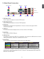
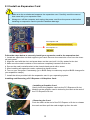
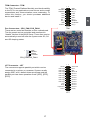
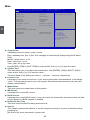
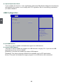
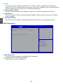
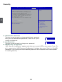
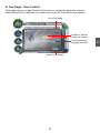
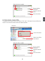
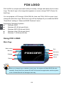
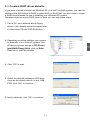
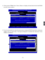
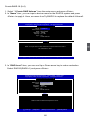
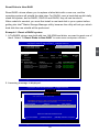
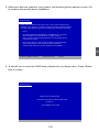
4. Press <Space> key to select it and press <Enter>, it returns to the main menu. You
can see the 74.5GB disk is offline, and actions of Recovery change from Contious
Update mode to On-Request.
5
Intel(R)
Storage
Technology
- Option
ROM - 10.0.0.1032 Intel(R)
MatrixRapid
Storage
Manager
option ROM
v5.0.0.1011
ICH9R wRAID5
Copyright(C) 2003-10
RightsReserved.
Reserved.
Copyright(C)
2003-04 Intel
Intel Corporation. All
Corporation All Rights
[ MAIN MENU ]
1. Create RAID Volume 3. Reset Disks to Non-RAID
4. Acceleration
Recovery Volume
Options
2. Delete RAID Volume
5.
Options
5. Exit
[ DISK/VOLUME INFORMATION ]
RAID Volume :
ID Name
Level
Stripe
Size Status Bootable
0
TryRecovery Recovery(OnReq) N/A 74.5GB NeedUpdate Yes
Physical Disks:
Port Drive Model 0
Hitachi HDS72161
1
ST380811AS 2
SAMSUNG HD161HJ
3
ST380815AS Serial #
PVF904Z21G2JZM
5PS1TAGW
S0V3J9APA30524
5RW1CA37
Size
149.0GB
74.5GB
149.0GB
74.5GB
Type/Status(Vol ID)
Recovery Disk(0)
Offline Disk(0)
Member Disk(0)
Non-RAID Disk
[↑↓]-Select [ESC]-Exit [ENTER]-Select Menu
100
Exit RAID BIOS
1. Take TryRAID5 as an example, select “5. Exit” in main menu and press <Enter>.
The screen displays :
Intel(R)
Storage
Technology
- Option
ROM - 10.0.0.1032 Intel(R)
MatrixRapid
Storage
Manager
option ROM
v5.0.0.1011
ICH9R wRAID5
Copyright(C) 2003-10
RightsReserved.
Reserved.
Copyright(C)
2003-04 Intel
Intel Corporation. All
Corporation All Rights
[ MAIN MENU ]
1. Create RAID Volume 3. Reset Disks to Non-RAID 2. Delete RAID Volume
4. Recover Volume Options
5. Exit
[ DISK/VOLUME INFORMATION ]
RAID Volume :
ID Name
Level Stripe
Size Status Bootable
0
TryRAID5
RAID5(Parity) 64KB 149.1GB Normal Yes
[ CONFIRM EXIT ]
Physical Disks:
Model AreSerial
you sure
(Y/N): Type/Status(Vol ID)
Port Drive
# you want to exit? Size
0
Hitachi HDS72161
PVF904Z21G2JZM
149.0GB Member Disk(0)
1
ST380811AS 5PS1TAGW
74.5GB Member Disk(0)
2
SAMSUNG HD161HJ S0V3J9APA30524
149.0GB Member Disk(0)
3
ST380815AS 5RW1CA37
74.5GB Non-RAID Disk
5
[↑↓]-Select [ESC]-Exit [ENTER]-Select Menu
2. Press <Y> to exit Intel® Matrix Storage Manager program. The system will enter
BIOS setup.
3. Shut down the computer, remove the Non-RAID disk, and we will continue for
Windows OS installation. If you do not remove irrelevant hard disk, Windows may
detect it during the installation, and you could be confused.
4. Remove any diskette from floppy drive.
5. Restart computer to start Windows installation.
101
CA
UT
IO
N
5-4 Install a New Windows XP
!
When
you set the SATA Mode in BIOS to either AHCI or RAID, you need to
follow these steps to install your Windows XP system.
1.Press <DEL> to enter BIOS Setup during POST.
2. Insert the Windows installation CD into the optical drive.
3.Set the “Boot Option #1” to “SATA: ATAPI DVD ...”, save changes and exit the BIOS
setup.
Aptio Setup Utility - Copyright (C) 2010 American Megatrends, Inc.
Main Advanced Chipset Boot Power Health Security Save
& Exit
Boot
Boot Configuration Bootup Numlock State
[On]
Select the keyboard NumLock
state
Quiet Boot
[Enabled]
CSM16 Module Version
07.64
Boot Option Priorities
Boot Option #1
[SATA: ATAPI DVD ...]
5
CD/DVD ROM Drive BBS Priorities
→ ←: Select Screen
↑ ↓: Select Item
Enter: Select
+/-: Change Opt.
F1: General Help
F2: Previous Values
F3: Optimized Defaults
F4: Save & Exit
ESC: Exit
Version 2.02.1205. Copyright (C) 2010 American Megatrends, Inc.
4.The computer will reboot, and it will start installing Windows Operating System.
Watch the screen carefully, when the following picture appears, press <F6> key
immediately. If you forgot to do this, PC will go to an fatal blue screen, and you
may need to reboot the system again. PC may not respond to your <F6> input
immediately, and it keeps loading files until the next screen displays.
Windows Setup
Press F6 if you need to install a third party SCSI or RAID driver.
102
5.After some files are copied to your system, the following picture appears, press <S>
to continue the specific driver installation.
Windows Setup
Setup could not determine the type of one or more mass storage devices
installed in your system, or you have chosen to manually specify an adapter.
Currently, Setup will load support for the following mass storage device(s):
<none>
* To specify additional SCSI adapters, CD-ROM drivers, or special
disk controllers for use with Windows, including those for
which you have a device support disk from a mass storage device
manufacturer, press S.
* If you do not have any device support disks from a mass storage
device manufacturer, or do not want to specify additional
mass storage devices for use with Windows, press ENTER.
5
S=Specify Additional Device ENTER=Continue F3=Exit
6. It will ask you to insert the RAID driver diskette into you floppy drive. Press <Enter>
after it is done.
Windows Setup
Please insert the disk labeled
manufacturer-supplied hardware support disk
into Drive A:
* Press ENTER when ready
ENTER=Continue ESC=Cancel F3=Exit
103
7. Depending on South Bridge chip of your system, select appropriate driver for it.
Here, we choose Intel® ICH8R/ICH9R/ICH10R/D0/PCH SATA RAID Controller.
Press <Enter> to select it.
Windows Setup
You have chosen to configure a SCSI Adapter for use with Windows,
using a device support disk provided by an adapter manufacturer.
Select the SCSI Adapter you want from the following list, or press ESC
to return to the previous screen.
Intel(R) ICH7R/DH SATA RAID Controller
Intel(R) ICH7MDH SATA RAID Controller
ICH8R/ICH9R/ICH10R/D0/PCH
SATA
RAID Controller
Intel(R) ICH8R/ICH9R/ICH10R
SATA RAID
Controller
Intel(R) ICH8M-E/ICH9M-E/PCHM SATA RAID Controller
5
ENTER=Select F3=Exit
8. A confirmation message pops out to double check if the driver is really what we
wanted. Press <Enter> to continue.
Windows Setup
Setup will load support for the following mass storage device(s):
Intel(R) ICH8R/ICH9R/ICH10R/D0/PCH SATA RAID Controller
* To specify additional SCSI adapters, CD-ROM drivers, or special
disk controllers for use with Windows, including those for
which you have a device support disk from a mass storage device
manufacturer, press S.
* If you do not have any device support disks from a mass storage
device manufacturer, or do not want to specify additional
mass storage devices for use with Windows, press ENTER.
S=Specify Additional Device ENTER=Continue F3=Exit
104
9. Windows will display the partition of your system, you have to create partitions as
many as you wish, assign them C:, D: or E: drive names. After partitions were done,
you can press <Enter> to continue. It will ask you to format your hard disk, then
copy files...etc., until the whole Windows is setup.
Windows XP Professional Setup
The following list shows the existing partitions and
unpartitioned space on this computer.
Use the UP ad DOWN ARROW keys to select an item in the list.
● To set up Windows XP on the selected item, press ENTER.
● To create a partition in the unpartitioned space, press C.
● To delete the selected partitions, press D. 305251 MB Disk 0 at id 0 on bus 0 on iaStor [MBR]
Unpartitioned space
305251 MB
5
ENTER=Install C=Create Partition F3=Quit
10. You must always keep RAID diskette in the floppy drive during Windows XP
installation, otherwise, Windows may ask you to put it inside again by below
message. There are many times Windows XP may copy files from the floppy drive,
please remember.
11. Follow the Windows XP install processes to finish the set up.
Windows XP Professional Setup
Insert the disk labeled:
Intel Matrix Storage Manager driver
into drive A:
* Press ENTER when ready
F3=Quit ENTER=Continue
105