1
SECTION 4 – MAINTENANCE
4.0
GENERAL
No routine maintenance is required on the meters or controllers, other than occasional
cleaning and re-calibration :
After 3 or 4 years when the unit is run with a ultra-clean and non corrosive gas.
After 1 or 2 years when the unit is run with a low purity gas and/or a corrosive gas.
Cleaning can be performed by removing the unit from the system, cleaning inlet and outletfittings separately and pumping alternately reverse and forward for 5 minutes in each
direction with a solvent system (one micron maximum absolute filtration).
Next, the unit must be blown with N2 for 30 minutes minimum.
Reinstall cleaned fittings.
In extreme cases of contamination, it may be necessary to separately clean the sensor, the
bypass and the valve.
4.1. DISASSEMBLY AND ASSEMBLY PROCEDURES
If you disassemble the mass flow controller, it will need recalibration in order to reach the
specifications given in this manual. If the mass flow controller appears to have a fault, first
perform the checks in the troubleshooting section, as it may not be necessary to dismantle
the valve. Prior to disassembly, make sure the unit has been purged with a dry inert gas.
WARNING : if it becomes necessary to remove the controller from the system after exposure
to toxic, pyrophoric, flammable or corrosive gas, purge the controller thoroughly with a dry
inert gas such as nitrogen, before disconnecting the gas connections. Failure to purge the
controller could cause a fire or explosion resulting in death.
CAUTION : the electronic circuitry contains CMOS and NMOS components. These are easily
damaged by static electricity, and usual precautions should be taken when installing,
dismantling or adjusting the mass flow controller.
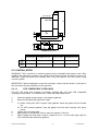
4.1.0 DISASSEMBLY PROCEDURE
0. Remove any mounting plate that may be under the mass-flow.
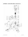
1. Unscrew in- and outlet-fittings 7 and 8 with a 1" wrench.
2. Unscrew 14 and remove the cover 19.
3. Remove the sensor-screws 15 with a 2.5mm hex screw driver, after having the lead wires
unsoldered from the p.c. board. Handle the sensor 2 with care.
4. Remove the screw 33 in the bottom of the valve.
5. Unsolder the magnet actuator wire from the pc board, then remove the 4 screws which
hold the magnet to valve body. Then carefully lift the magnet. Do not turn the mass-flow
controller now.
6. Carefully remove the top housing 24 with the bellows and plunger assembly from the
valve housing 23. Then carefully unscrew the lower bellow.
7. Remove the 4 screws 9 in the top of the top housing 24 which hold the top ring assy 29.
Then remove the bushing 32.
AFC 202 User’s Manual
15
D-10-032 V00