1
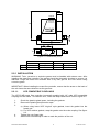
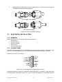
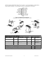
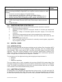
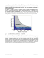
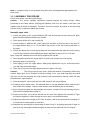
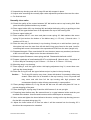
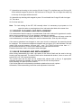
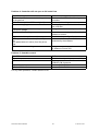
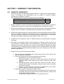
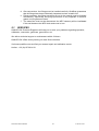
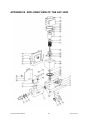
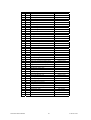
AFC 202D
AFC 202 D User’s Manual
1
D 10-018 V04
QUALIFLOW Montpellier (headquaters)
350, rue A. Nobel
BP7- 34935 MONTPELLIER
CEDEX 9
France
tel: +33 4 67 99 47 47
fax: +33 4 67 99 47 48
QUALIFLOW Inc,
24 Goose Lane
TOLLAND CT-06084
CALIFORNIA - USA
tel: +1 860.871.04.01
fax: +1 860.871.92.33
QUALIFLOW Technical Center
909 Boggs Terrace
Fremont, CA-94539
CALIFORNIA - USA
tel: +1 510 440 93 74
fax: +1 510 440 93 75
QUALIFLOW Japan
3F Hattori Bldg., 4-30-14, Yotsuya, Shinjuku-ku
Tokyo 160-0004
Japan
Tel: +81 (0)3 5366 2801
Fax: +81 (0)3 3341 3513
AFC 202 D User’s Manual
2
D 10-018 V04
Reference D-10-018
Document Name
File Name
Author
Visa
Date
Olivier Léonel 03/07/02
Author
Olivier Léonel
Olivier Léonel
Olivier Léonel
Olivier Léonel
Date
17/11/00
18/01/01
26/02/01
03/07/02
Identification
Revision
04
User's Manual AFC 202D
AFC202D Manual.doc
Control
Verified
Visa
Date
Didier Stupfler 03/07/02
History
Description
Initial Version
Exploded View added
New section layout
Specification update
Date
03/07/02
Approved
Visa
Date
P. Garnier
03/07/02
Revision
00
01
03
04
Status
Issued
Issued
Issued
Issued
2002 QUALIFLOW Montpellier, France. This document contains information proprietary to
QUALIFLOW and shall not be used for engineering, design, procurement or manufacture in
whole or in part without consent of QUALIFLOW.
AFC 202 D User’s Manual
3
D 10-018 V04
SECTION 1 - INTRODUCTION .............................................................................................. 5
1.0 AFC 202.D: DIGITAL MASS FLOW CONTROLLER .............................................. 5
1.1 AFC 202.D : "USER's MANUAL" .............................................................................. 5
1.2 SPECIFICATIONS....................................................................................................... 6
1.3 CALIBRATION FEATURES ...................................................................................... 7
SECTION 2 - INSTALLATION................................................................................................ 8
2.0 INTRODUCTION ........................................................................................................ 8
2.1 UNPACKING ............................................................................................................... 8
2.2 MECHANICAL INSTALLATION.............................................................................. 8
2.3 ELECTRICAL INSTALLATION .............................................................................. 10
2.4 CHECKS BEFORE STARTING UP.......................................................................... 12
2.5 DIGITAL CARD. ....................................................................................................... 12
2.6 COMMUNICATION MODES................................................................................... 16
SECTION 3 – MAINTENANCE............................................................................................. 17
3.0 GENERAL ..................................................................................................................... 17
3.1 DISASSEMBLY AND ASSEMBLY PROCEDURES ................................................. 17
3.2 SENSOR CLEANING AND REPLACEMENT ........................................................... 20
3.3 VALVE CLEANING AND REPLACEMENT ............................................................. 20
SECTION 4 – TROUBLESHOOTING ................................................................................... 21
4.0 INITIAL CHECK. ...................................................................................................... 21
4.1 SYMPTOMS............................................................................................................... 21
SECTION 5 - WARRANTY AND SERVICES ...................................................................... 23
5.0 PRODUCT WARRANTY.......................................................................................... 23
5.1 SERVICES.................................................................................................................. 24
APPENDIX A GAS PROCESS NUMBER.......................................................................... 25
APPENDIX B EXPLODED VIEW OF THE AFC 202D .................................................... 26
APPENDIX C GENERAL MFC PRINCIPLES ................................................................... 28
AFC 202 D User’s Manual
4
D 10-018 V04
SECTION 1 - INTRODUCTION
1.0
AFC 202.D: DIGITAL MASS FLOW CONTROLLER
The QUALIFLOW Digital Mass Flow Controller AFC202.D offers the highest degree of
accuracy and reliability in controlling high gas flows.
This range has been designed specifically to prevent contamination and particle deposition. It
is therefore ideal when using in semiconductor and optical fiber manufacturing processes. It
takes benefit from the digital technology : new features such as alarm and maintenance
functions are available (with the free QUALIFLOW’s PC interface digisoft). With a specially
developed algorithm, the regulation is obtained without overshoot and during the transient
time, the readout matches the real flow.
1.1
AFC 202.D : "USER's MANUAL"
This manual includes the following sections :
Section 1. Introduction : contains specifications and calibration features.
Section 2. Installation : contains all the information necessary to unpack the AFC202.D
without causing contamination, install the AFC202.D and check the installation before
starting up. All data related to digital card and use of a PC with RS232 connection are
developed.
Section 3.Maintenance.
Section 4.Trouble-shooting.
AFC 202 D User’s Manual
5
D 10-018 V04
1.2
SPECIFICATIONS
AFC 202.D
Flow Range
From 30 slm to 400 slm N2
Control Range
Between 2 and 100% F.S
Valve type
Electromagnetic
Valve Rest position
Normally Open or Close
± 1% of setpoint
if setpoint > 30% of F.S.
± 0.3% of F.S.
Accuracy
if setpoint < 30% of F.S.
Linearity
± 0.2% F.S (per cal Gas)
Repeatability
± 0.15% F.S
Step Response Time
<= 2.5 sec (SEMI E17-91
Temperature Range
Between 5 and 50°C
Temperature Coefficient
< 0.05% F.S /°C
Maximum Inlet Pressure
10 bar
Min. Differential Pressure 1.5 bar for 30 slm
2 bar for 50 slm
2.5 bar for 100 slm
3 bar for 200 slm
4.5 bar for 400 slm
Pressure Coefficient
< 0.1% F.S /bar
Power Input Requirement + 15 VDC –15V ; 600mA
Set Point Signal
From 0 to 5 VDC
Flow Outpout Signal
From 0 to 5 VDC
Electrical Connector
Sub-D 15
Construction materials
Leak integrity
316L stainless Steel
< 2.10-8 sccm/sec (He)
Standard Seals
316L Stainless Steel
Seals on request
Neoprene for NH3
Viton for other gases
Fittings
On request
Options
Kalrez seals
Separated electronics
Device Net or PROFIBUS
RS 485/MODBUS
AFC 202 D User’s Manual
6
D 10-018 V04
1.3
CALIBRATION FEATURES
The Mass Flow Controllers are calibrated close to customer’s process. Without customer’s
information, the MFCs are calibrated under standard conditions.
1.3.0 STANDARD CONDITIONS
Without special conditions specified by the customer, the MFC is calibrated under the
following standard conditions :
Pressure conditions :
Pressure Outlet : Atmospheric
Delta Pressure : between 500 mbars and 3 bars
Dynamic adjustment : no overshoot
The mounting position (horizontal, vertical inlet up or down) should be specified by the
customer to ensure the best accuracy .
1.3.1 MANUFACTURING ENVIRONMENT
The MFCs are assembled, calibrated, packaged and controlled in a class 100 cleanroom.
1.3.2 QUALITY CONTROL
Each MFC is controlled 24 hours after manufacturing on a different calibration bench. The
accuracy, the dynamic response, the stability to pressure variations are double checked.
AFC 202 D User’s Manual
7
D 10-018 V04
SECTION 2 - INSTALLATION
2.0
INTRODUCTION
This four part section contains all the information necessary to install the AFC202.D mass
flow controllers.
•
2.1 - UNPACKING;
•
2.2 - MECHANICAL INSTALLATION;
•
2.3 - ELECTRICAL INSTALLATION;
•
2.4 - CHECK BEFORE START UP.
•
2.5 - DIGITAL CARD.
•
2.6 - COMMUNICATION MODES.
2.1
UNPACKING
The AFC202.D mass flow controller are manufactured under clean room conditions, and has
been packed accordingly upon receipt. The cardboard packing should be checked for
damage. If there is visible damage, please notify your local QUALIFLOW sales office at
once. In order to minimize contamination of clean rooms, the unit has been packed in two
separately sealed plastic bags. The outside bag should be removed in the entrance to the
clean room. The second bag should be removed when you install the unit.
2.2
MECHANICAL INSTALLATION
2.2.0 GENERAL
Most applications will require a positive shutoff valve in line with the mass flow controller.
Pressurized gas trapped between the two devices can cause surge effects, and
consideration must be given to the sitting of the shutoff valve (upstream or downstream) in
relation to the process sequencing. As far as the process parameters will allow this, it is
recommended that you install an in-line filter upstream to the controller in order to prevent
from contamination.
The AFC202.D can be mounted in any position. The atmosphere should be clean and dry.
The mounting should be free from shock or vibration. Mounting dimensions are shown in
figure 2-1. Prior to installation, ensure that all the piping is thoroughly cleaned and dried. Do
not remove the protective end caps until you are ready to install the controller.
AFC 202 D User’s Manual
8
D 10-018 V04
15 pin D
AFC 202D
MASS FLOW
CONTROLLER
182
QUALIFLOW
http://www.qualiflow.com
20
B
A
24
30
30
45
4 holes M5
Figure 2-1 Dimensions (mm)
A (mm)
B (mm)
AFC 202
VCR 3/8” MM
Swagelok 3/8
181,4
183,3 (incl. nuts)
123
123
AFM 302
VCR 3/8” MM
Swagelok
141.9
143.8 (incl. nuts)
83.5
83.5
2.2.1 INSTALLATION
WARNING: Toxic, corrosive or explosive gases must be handled with extreme care. After
installing the mass flow controller, the system should be thoroughly checked to ensure it is
leak-free. Purge the mass flow controller with a dry inert gas for one hour before using
corrosive gases.
IMPORTANT: When installing the mass flow controller, ensure that the arrow on the back of
the unit shows the same direction as the gas-flow.
2.2.1.1.
VCR COMPATIBLE COUPLINGS
The AFC50.MD mass flow controller is normally supplied with 1/4" male VCR compatible
couplings on both sides. To install the AFC, follow the steps listed below. Refer to figure 2-2.
1.
2.
3.
4.
5.
Check the gland to gland space, including the gaskets.
Remove the plastic gland protector caps.
a) When using loose VCR "original" style gaskets, insert the gasket into the
female nut.
b) For VCR retainer gaskets, snap the gasket onto the male coupling. See figure
2-2.
Tighten the nuts finger tight.
Scribe both nut and body in order to mark the position of the nut.
AFC 202 D User’s Manual
9
D 10-018 V04
6.
While holding the body with a wrench, tighten the nut : 1/8 turn past finger tight for
316L stainless steel and nickel gaskets.
VCR original style gasket
VCR retainer gasket
Figure 2-2 VCR compatible couplings
2.3
ELECTRICAL INSTALLATION
2.3.0 GENERAL
Within this section, you will find the following sub-sections:
• Connections.
• Digital functions.
• Pressure control.
• Ratio control.
• Communication plug.
2.3.1 CONNECTIONS
The electrical connections of the AFC202.D are made through a sub D 15 connector (see
figure 2-3). RS 232 adapters for use in maintenance functions are available (model 4).
Digital’s card sub D 15 connector :
9. Signal Com
10. Power Com
11. RS232 Tx
12. Valve voltage
13. TTL2
14. GND
15. TTL3
1. Signal Com
2. Readout
3. TTL1
4. RS232 GND
5. +15 VDC
6. -15 VDC
7. RS232 Rx
8. Setpoint
Figure 2-3 Pin arrangement for digital Card connector.
Dedicated interface connector is available to allow digital MFC connection to work with other
pin arrangement, according to figure 2.4. This second pin arrangement is compatible with the
AFC 202 D User’s Manual
10
D 10-018 V04
AFC 202 analog QUALIFLOW Mass Flow Controller. A card edge adapters coupled with a
RS232 cable is available. The card edge connection is widespread in the industry.
9. Setpoint
10. Power Com
11. Signal Com
12. Test Softstart
13. Zero command
14. -15 VDC
15. Not used
1. Case GND
2. Signal Com
3. Readout
4. +15 VDC
5. Zero test
6. +5 VDC
7. Valve voltage
8. Extra output
Figure 2-4 Adapters pin arrangement
(compatible with QUALIFLOW’s analog AFC 202)
MODEL 1
D Sub 15 pin
Male
RS232C
D Sub 9 pin
Female
MODEL 4
D Sub 15 pin
Male
Card-edge
20 pin
RS232C
D Sub 9 pin
Female
D Sub 15 pin
Female
D Sub 15 pin
Female
MODEL 2
MODEL 3
D Sub 15 pin
Female
D Sub 15 pin
Female
Card-edge
20 pin
Connectors Conversion Adapters
QUALIFLOW MFC / Connector Replaced MFC / Connector
Analog AFC50/AFM D Sub 15
Main MFC’s
Card-edge
55
pin
Digital All Series
D Sub 15
Main MFC’s
Card-edge
pin
Digital All Series
D Sub 15
Analog AFC50/AFM D Sub 15
pin
55
pin
Digital All Series
D Sub 15
Main MFC’s
D Sub 15
pin
pin
0-5V to 4-20mA Conversion Adapters
MFC Type
QUALIFLOW Analog AFC50/AFM55
QUALIFLOW Digital and Main MFC’s with D Sub 15 pin connector
AFC 202 D User’s Manual
11
Model Part Number
1
Q201733-01
1
2
3
4
4
Q201733-07
Q201733-08
Q201733-09
Q201733-10
Q201733-06
Model
3
3
Part Number
Q201733-05
Q201733-15
D 10-018 V04
Other Accessories
Part
Number
Q 2001733-12
Control and Power Supply Kit for QUALIFLOW Digital MFC’s all series :
When connecting individually a Digital MFC to a computer use this interface kit, which
includes:
• Connector conversion adapter, P/N q 2001733-06
• Power supply assy 120/230 VAC, ±15VDC, P/N Q2001733-14
• Power cord from power supply to MFC, length 1 meter, P/N Q2001733-13
• RS232C cord from MFC to computer, length 2 meters, P/N Q2001733-11
2990924Q
Connecting cord for Analog AFC50/AFM55 or digital MFC’s all series :
• D Sub 15 pin female connector (MFC side), wires ready to weld at the other
end
• Length 5 meters
2.4
CHECKS BEFORE STARTING UP
Before operating the mass flow controller the following checks should be completed :
1.
Check that tubing is leak proof.
2.
Check the process sequence and proper function of all other gas components
involved.
3.
Check the voltage of command signals and power supply to the mass flow
controller.
4.
Check that the appropriate gas type is being supplied at the rated pressure.
5.
Allow the mass flow controller to warm up for 20 minutes, then check the zero
level output.
6.
Use dry inert gas for test runs.
7.
Prior to using the mass flow controller for extremely corrosive gases, purge with a
dry inert gas for one hour.
2.5
DIGITAL CARD.
2.5.0 INTRODUCTION
QUALIFLOW has designed and developed a digital card for its Mass Flow Controllers (MFC)
that take advantages of the full potential of digital technology. Not only enabling digital
communication, these cards improve MFC accuracy and control using a numerical control
algorithm. They store several calibration curves, therefore QUALIFLOW customers can
reduce the number of references that they use. They also make maintenance operations
easier : through alarm functions and PC diagnostic via RS232.
The development of the digital technology has brought great improvements in :
• Accuracy
• Control
• Additional capabilities
This new digital card is 100% compatible with previous QUALIFLOW analog Mass Flow
Controllers. However the digital mode is best used for maintenance functions or in calibration
mode. The RS485 communication and the device net communication allow the use in digital
communication mode with standard industry protocol.
2.5.1 A BETTER ACCURACY
All analog MFC's are calibrated with potentiometers at three points : 2%, 50% and 100% FS
to make the error at 0%, 25%, 50%, 75% under 1% FS. The numerical MFC's are calibrated
at more than 6 points and the response curve is then calculated. Their accuracy is ± 1% of
AFC 202 D User’s Manual
12
D 10-018 V04
setpoint if setpoint > 30% of F.S., ± 0.3% of F.S. if setpoint < 30% of F.S. So the linearity is
much better at small setpoints (see the following graph).
Most of digital MFCs use linear interpolation to calculate the response curve whereas the
QUALIFLOW digital board achieved better accuracy, with lower calibration points thank to
polynomial interpolation.
The RS232 or RS485 or Device net connection let you to change the calibration curve by
choosing the corresponding number without disconnecting the MFC. 10 calibration curves
can be stored in memory. To maintain the best accuracy the maximum factor between two
full scales of two several calibrations is 3.
The set point and the measure are converted by 16 bits CAN for the best accuracy. The
analog readout is converted by 12 bits CNA which does not alter the accuracy of the flow.
2.5.2 AN OPTIMIZED NUMERICAL CONTROL
The control of the gas flow is made by a numerical algorithm which assumes a control
without overshoot at any set point. Each calibration curve is stored with its own optimised
regulation parameters which are determined by calculation. An analog control is fixed by the
electronic components and can not be adapted to each gas and to each full scale. For
example, an analog regulation can not avoid overshoot at low flow rates whereas an
algorithm gives fine control at any set point. The following typical curves compare the analog
regulation with the numerical one. As the response time of the digital MFC's are more
repeatable and do not depend on electronic components. So digital MFC's have closer
transient behaviours, which brings a great improvement in process with mixed gases.
AFC 202 D User’s Manual
13
D 10-018 V04
2.5.3 RAMPING
The ramping function increases linearly the set point in order to give a progressive raise in
the flow. It could be used to keep stoechiometric values during transient response of a
process. The increase of the set point by unit time is chosen by the user (see software
manual).
2.5.4 SOFT-START
The soft start function closes the valve if the set point is lower than 1%F.S. For a new set
point greater than 1%F.S, the regulation starts after a delay that is chosen by the user.
This way you can avoid big overshoots caused by pressure drop, when starting a process.
AFC 202 D User’s Manual
14
D 10-018 V04
2.5.6 IN SITU CALIBRATION
The calibration can be automatically made by calibration devices with a serial
communication. The calibration is made with six points without potentiometers. The
QUALIFLOW software allows to calibrate the MFC from the ‘Molblox’ device (Caltechnics).
2.5.7 AUTO-ZERO
The function AUTO-ZERO corrects the drift of the MFC. It can be done automatically or by
the user. The correction can not exceed 0.5%.
2.5.8 ADDITIONAL CAPABILITIES
Additional capabilities are customized by a free PC Interface (see the software’s manual in
the CD).
2.5.8.0
LED INDICATOR
The MFC contains three LEDS located on the left hand side.
The left LED is the watchdog LED. When blinking, it indicates whether the MFC is on power
or not. A quick blinking (several times per second) indicates that the MFC is working on a
analog mode.
The second LED indicates whether the regulation is obtained (switched on) or not (switched
off).
Switched on, the third LED indicates an error as : a sensor error
a communication error
a EEPROM error
a valve type error
a converter (A/D) error
2.5.8.1
ADJUSTABLE ALARM
The user chooses three parameters, the delta min, the delta max and the delay alarm, in
order to adjust the regulation alarm. Delta min and delta max (in ‰ FS) are the maximum
differences between the readout and the set point to get before the delay time. If the MFC
AFC 202 D User’s Manual
15
D 10-018 V04
does not correctly control, the alarm is on until the user switches it off. For example, if the
pressure is too low, the MFC could not regulate the flow The alarm signal will be generated
until the user switches it off.
This alarm can be switched off by soft .
2.5.8.2
TOTALIZER
The totalizer indicates the cumulative flow in % FS since the last initialisation. It is useful to
have a look on your gas consumption.
2.5.8.3
DATA STORING / RETRIEVING
The set point, the valve voltage and the readout are stored at a frequency of 2 times a
minute during 6 hours and can be saved as an excel file. These data allow the diagnostic of
sensor drift or pressure drop.
For example an increasing in valve voltage for the same set point could be due to
contamination or corrosion.
Data can be scanned and retrieved at any time without interruption while the MFC runs in
control mode.
2.6
COMMUNICATION MODES.
In addition to the ability to use this digital MFC on analog mode with the advantage of
communication via serial RS-232C for maintenance, calibration or individual control (DB 15
connector, following options are available :
RS-485 option: can control up to 32 MFC's under MODBUS protocol (RJ11 connector).
DeviceNet or PROFIBUS option: this mode allows communication with high speed protocol.
For more information during utilization, contact QUALIFLOW, France.
AFC 202 D User’s Manual
16
D 10-018 V04
SECTION 3 – MAINTENANCE
3.0 GENERAL
No routine maintenance is required on the meters or controllers, other than occasional
cleaning and re-calibration :
After 3 or 4 years when the unit is run with a ultra-clean and non corrosive gas.
After 1 or 2 years when the unit is run with a low purity gas and/or a corrosive gas.
Cleaning can be performed by removing the unit from the system, cleaning inlet and outletfittings separately and pumping alternately reverse and forward for 5 minutes in each
direction with a solvent system (one micron maximum absolute filtration).
Next, the unit must be blown with N2 for 30 minutes minimum.
Reinstall cleaned fittings.
In extreme cases of contamination, it may be necessary to separately clean the sensor, the
bypass and the valve.
3.1 DISASSEMBLY AND ASSEMBLY PROCEDURES
If you disassemble the mass flow controller, it will need recalibration in order to reach the
specifications given in this manual. If the mass flow controller appears to have a fault, first
perform the checks in the troubleshooting section, as it may not be necessary to dismantle
the valve. Prior to disassembly, make sure the unit has been purged with a dry inert gas.
WARNING : if it becomes necessary to remove the controller from the system after exposure
to toxic, pyrophoric, flammable or corrosive gas, purge the controller thoroughly with a dry
inert gas such as nitrogen, before disconnecting the gas connections. Failure to purge the
controller could cause a fire or explosion reasulting in death.
CAUTION : the electronic circuitry contains CMOS and NMOS components. These are easily
damaged by static electricity, and usual precautions should be taken when installing,
dismantling or adjusting the mass flow controller.
3.1.0 DISASSEMBLY PROCEDURE
0. Remove any mounting plate that may be under the mass-flow.
1. Unscrew in- and outlet-fittings 7 and 8 with a 1" wrench.
2. Unscrew 14 and remove the cover 19.
3. Remove the sensor-screws 15 with a 2.5mm hex screw driver, after having the lead wires
unsoldered from the p.c. board. Handle the sensor 2 with care.
4. Remove the screw 33 in the bottom of the valve.
5. Unsolder the magnet actuator wire from the pc board, then remove the 4 screws which
hold the magnet to valve body. Then carefully lift the magnet. Do not turn the mass-flow
controller now.
6. Carefully remove the top housing 24 with the bellows and plunger assembly from the
valve housing 23. Then carefully unscrew the lower bellow.
7. Remove the 4 screws 9 in the top of the top housing 24 which hold the top ring assy 29.
Then remove the bushing 32.
AFC 202 D User’s Manual
17
D 10-018 V04
Note: If o-rings are dirty, cut or cracked, they have to be exchanged with appropriate new,
clean ones.
3.1.1 ASSEMBLY PROCEDURE
First mount sensor, inlet and outlet fittings.
Caution : The sensor capillary sometimes extends beyond the seals o-rings. When
positioned on the base without verifying that capillary ends fit in the holes in the base, the
capillary can be bend or damaged. Therefore, center the sensor by means of the mounting
screws, hold it up and then fasten the screws.
Normally open valve
1. Check the quality of the contact between 3/8" ball and its seat on top housing 24. Both
parts should be polished without any scratch.
2. Place upper bellow 40 in top housing 24.
3. Select number of washers M3, crown spring 30 and ball, so that the end of the stem of
the upper bellow assy is 1 to 1.5 mm below top surface of the top housing (with ball on
the seat).
4. Select now place of the crown spring between the washers so that when the crown spring
is on its seat, the ball is lifted halfway the space adjusted in step 3 (0.5 to 0.75 mm).
Note : keep ball, washers and crown spring together with nut M3.
5. Now, lengthen carefully the upper bellow so that it just contact the crown spring.
6. Mounting assy in top housing.
7. Place spring 6 over the upper bellow. Add spring adjustment ring 31 and screw these
over half way the thread length.
8. Place the O-ring over the upper bellow and put in place in the top.
Caution :
The O-ring must be very clean ( clean with alcohol if necessary) without any
scratch. Same think for its chamber in the top housing. If not, very small leak may occur and
with time full the top housing with high pressure with consequence that the valve will stay
permanently in open position.
9. Place bushing 32, top ring 29 and the 4 M3 screws 9, do not yet tighten.
10. Preparing lower bellow assy : Be assured there is no gap between bellow and and the
part screw at the bottom. Unscrew and counter sunk the bellow part as necessary.
11. Now, screw and tighten the lower bellow to the stem, coming out the top housing (remove
first the M3 nut putted during step 4).
12. Press on the stem, so to center the ball into the seat, then tighten the 4 screws 9. Tight
the screws together in order to keep the inner assy in its centered position.
13. Adjust the lower bellow length at 47.5mm as when it will be mounted into the housing 23
it should not be compressed or extended.
14. Assemble top housing 24 to the housing 23 with O-ring 37 on bellow assy and O-rings 36
and 38 on top housing but without magnet in place for first leak test of the O-ring 26.
AFC 202 D User’s Manual
18
D 10-018 V04
15. Assemble top housing now with O-rings 36 and with magnet in place.
16. Adjust valve according the normally open valve adjustment procedure then test the valve.
17. Do final leak test
Normally close valve
18. Check the quality of the contact between 3/8" ball and its seat on top housing 24A. Both
parts should be polished without any scratch.
19. Place upper bellow 40 in top housing 24A and adjust bellow by pulling or pushing so that
the top of the upper bellow stem 40 is adjusted to the top of the housing 24A.
20. Remove upper bellow 40.
21. Place washers M3 27 over stem and place crown spring 30. Add washers that crown
spring 30 just touches the bottom of the bellow assy (+/- 0.5 mm). ( Normal value : 3
washers of 0.8 mm ).
22. Place the assy 40 (up side down) in top housing 24 and put on solid surface (seat up).
Now place ball over the stem from 40 with ball O-ring grove faced to the seat. Look for
contacting ball to seat. And measure the exposed end of M3 from the stem (length is A).
23. Disassemble again. Place now the ball 29 over the stem (same way as above) and screw
a M3 nut on the stem. Adjust nut to the same dimension as A.
24. Measure space B between crown spring and ball. Disassemble ball and nut M3.
25. Prepare a package of small washes M3 27 to a thickness B. (Normal value : 6 washers of
0.8 mm. May be necessary to put 5 0.8mm + 1 0.5mm or 5 0.8mm + 2 0.5mm).
26. Mounting assy in top housing.
27. Place spring 6 over the upper bellow. Add spring adjustment ring 31, screw these over
half way the thread length.
28. Place the O-ring 26 over the upper bellow and put in place in the top housing.
Caution :
The O-ring 26 must be very clean ( clean with alcohol if necessary) without any
scratch. Same think for its chamber in the top housing. If not, very small leak
may occur and with time full the top housing with high pressure with
consequence that the valve will stay permanently in open position.
12. Place package washers B, O ring 28 and the ball over the stem and place M 3 nut to
prevent dropping of the parts.
13. Place bushing 32, topring assy 29 and the 4 M3 screws 9, do not yet tight.
14. Preparing lower bellow assy: Be assured there is no gap between bellow and the part
screwed at the bottom. Unscrew and counter sunk the bellow part as necessary.
15. Now, screw and tighten the lower bellow to the stem, coming out the top housing (remove
first the M3 nut putted during step 12).
16. Adjust the lower bellow at 47.5mm as when it will be mounted into the housing 23 it
should not be compressed or extended.
AFC 202 D User’s Manual
19
D 10-018 V04
17. Assemble top housing to the housing 23 with O-ring 27 on bellow assy and O-rings 36,
38 but without magnet in place for first leak test of O-ring 26. Do not forget the snap ring
on the top of the upper bellow stem 40.
18. Assemble top housing with magnet in place. Do not Install the O-rings 36 with inert gas.
19. Test valve.
20. Do final leak test.
Note : For leak testing of the AFC 202 normally close it is necessary to put power on it to
open the valve or pumping down from inlet and outlet side at the same time.
3.2 SENSOR CLEANING AND REPLACEMENT
If it is determined that the sensor is contaminated, flush with a solvent in hypodermic needle,
while running a small wire (0.15 mm diameter, available on request).
Do not immerse the entire sensor assembly in a solvent; the solvent will keep under the
cover and destroy or at least change the sensor characteristics. Slow dry with nitrogen.
If the sensor resistance has changed or even open circuit is measured, the assembly should
be replaced. The measured resistance between red and green (R1) and between red and
yellow (R2) must be between 160 and 190 Ω and ΩR = R2-R1 must be less than ±1 Ω.
Check also that there is no short-circuit between the tube and the red wire.
Examine the sensor seals, and replace when damaged.
3.3 VALVE CLEANING AND REPLACEMENT
After having disassembly the valve, the status of the shut-off ball and the seat in the top
housing can be examined. The shut-off ball can be cleaned with alcohol, freon or even a HF
solution (5% HF, 95% deionised water).
The conical seat and the ball can be treated with solvent and a felt tip. If appropriate
polishing equipment is available, the seat and shut-off ball can be polished.
After polishing, the parts must be cleaned.
If the critical parts are unfortunately corroded or attacked too much, replace.
Afterwards, follow assembling instruction and adjustment instruction.
AFC 202 D User’s Manual
20
D 10-018 V04
SECTION 4 – TROUBLESHOOTING
4.0
INITIAL CHECK.
1.
Check the gas supply pressure and check that the flow-path to the mass flow
controller has been opened.
2.
Ensure that the power supply and command signals are correctly transmitted to
the D-connector pins on the PC-board.
3.
Check that the output signal matches the external reading. For pin assignments
see figure 2-3.
Use the following table to locate the fault.
4.1
SYMPTOMS.
Problem 1: Output reading, without gas flow, is not zero.
Possible cause
Action
1. Gas flow is actually present
2. Zero reading has drift less than 1.5%
Check closure of series shutoff valve.
Try ‘Autozero function’ by the software
Problem 2: Zero reading cannot be adjusted by autozero.
Possible cause
Action
Defective sensor.
Check that sensor voltage between red and
orange wires is equal to the voltage between
red and blue wires. Both must be 4 to 6 volts.
Contact QUALIFLOW for advice. If defective,
the controller may need replacing.
Problem 3: Valve will not close
Possible cause
Action
1. Check the Mfc is properly connected on the
gas line
2. Set-point is not zero
3. Incorrect solder pad connections
4. The Mfc is in digital mode and you use it with
a set-point voltage
5. The parameters min valve (for a NC) is too
high
The parameters max valve (for a No) is too low
6. Incorrect actuator voltage
Disconnect the MFC after following the
procedure
Check set-point voltage on PC-board pin 9
See the strap configuration
Change the control mode by the software
7. Incorrect nozzle adjustment
8. Plunger stuck
AFC 202 D User’s Manual
Increase or decrease one
parameter by the software
of
this
Voltage across actuator wires must be :
between 0V and 30V
Remove mass flow controller and readjust
nozzle.
Remove controller and clean up.
21
D 10-018 V04
Problem 4: Controller will not open to full scale flow
Possible cause
Action
1. Check the Mfc is connected in the good way
on the gas line
2. Incorrect setpoint on PC-board (pin 8)
3. Incorrect supply pressure
Disconnect the MFC after following the
procedure
Check setpoint voltage.
Check gas pressure at inlet side of mass
flow controller
4. The Mfc is in digital mode and you use it with Change the control mode by the software
a set-point voltage
5. Incorrect flow reading
Check the numerical readout found by the
software is correct
6. Incorrect solder pad connections
Check the strap configuration
7. The parameters max valve (for a NC) is too Increase or decrease one of this
low
parameter by the software
The parameters min valve (for a No) is too
high
8. Incorrect actuator voltage
Voltage across actuator wires must
be :between 0V and 30V
Problem 5: Unstable control
Possible cause
Action
1.Unstable pressure
2. Defective electronics
Check inlet and outlet pressure stability
Replace mass flow controller and contact
QUALIFLOW for advice.
Contact QUALIFLOW
Contact QUALIFLOW
3. Bad Regulation parameters
4. Defective Mechanics
For any other problems, contact QUALIFLOW.
AFC 202 D User’s Manual
22
D 10-018 V04
SECTION 5 - WARRANTY AND SERVICES
5.0
PRODUCT WARRANTY
1. Qualiflow products are guaranteed against defects in materials and workmanship if
used in accordance with specifications and not subject to physical damage,
contamination, alteration or retrofit.
Warranty periods (from the date of shipment) are the following :
AFC90MD series
3 years
AFC80MD, AFC310MD series
2 years
INFLUX, AFC50, AFC202, AFC260 & AFC261 series
1 year
2. Buyers undertake to check and inspect the goods and to notify Qualiflow of shipment
incidents by fax, phone or e-mail as soon as possible after receipting the goods.
3. During the warranty period, products must only be repaired by authorized Qualiflow
service centers; otherwise, the Qualiflow product warranty will be invalidated.
4. Repairs will be performed free of charge during the one-year warranty period. If MFCs
are out of warranty, Qualiflow will notify the owner of replacement or repair costs
before proceeding. Factory service and repairs are guaranteed 90 days. The warranty
excludes consumable materials and wear parts (in teflon, viton, etc.).
5. No MFC will be accepted for repair or warranty without a decontamination and purge
certificate.
6. Each MFC is individually checked (visual inspection of fittings, helium leak test and
flow calibration). Qualiflow shall not be responsible for any damage caused by gas
leakage or the use of a dangerous gas. Users are responsible for following the safety
rules applicable to each gas they use. Improper use of a Qualiflow MFC will void the
warranty, and MFCs that have been damaged as a result of improper use will not be
replaced by Qualiflow.
7. Specific warranty requirements are as follows :
a. Gas must be clean and particle-free, which means a filter must be fitted in the
gas line upstream of the MFC.
b. Gas must comply with the following pressure specifications:
i. Gas pressure must never exceed 10 bars.
ii. Differential pressure must be more than 500 mbar for full-scale flow
through the MFC valve unless an other value is specified in the user’s
manual.
iii. Differential pressure must be less than 3 bars for the MFC valve to
regulate without gas-flow oscillation unless an other value is specified
in the user’s manual.
iv. Pressure at the mass-flow inlet must be regulated by an accurate
pressure regulator to prevent gas-flow oscillation.
c. Electrical connection requirements are as follows:
i. The system must be wired carefully: non-observance of the pinout may
irreversibly damage the electronic board inside the MFC, in which case
the warranty will be invalidated.
ii. A stable power supply is required, with ripple below 5mV.
AFC 202 D User’s Manual
23
D 10-018 V04
d. Gas connections: the fittings must be handled carefully. Qualiflow guarantees
that all fittings have been individually inspected and are scratch-free.
e. Fitting procedure: the fitting procedure set out in the manual must be followed
meticulously. Specifically, the purge procedure is very important if corrosive
gases or toxic gases are used.
f. The mass-flow must not be dismounted: the MFC warranty will be invalidated
if the seal between the MFC block and cover is torn.
5.1
SERVICES
QUALIFLOW Products Engineers will help you to solve your problems regarding operation,
calibration, connection, gas flows, gas mixture, etc.
We deliver technical support or maintenance within 24 hours.
QUALIFLOW offers factory training on mass flow controllers.
Visit www.qualiflow.com and find your nearest repair and calibration center.
Hotline : +33 (0)4 67 99 84 31
AFC 202 D User’s Manual
24
D 10-018 V04
APPENDIX A GAS PROCESS NUMBER
Symbol
Gas Name
Number
NH3
Ar
AsH3
BCl3
CO
CCl4
Cl2
B2H6
SiH2Cl2
CHF3
CCl2F2
CF4
GeH4
He
H2
HCl
C2F6
Kr
CH4
CH3SiCl3
N2
NO2
NF3
N2O
O2
O3
PH3
C3H8
SiH4
SiF4
Si2H6
SO2
SF6
TiCl4
C4F8
SiHCl3
Air
Ammonia
Argon
Arsine
Boron Trichloride
Carbon Monoxide
Carbon Tetrafluoride
Chlorine
Dibirane
Dichlorosilane
Fluoroform
Freon-12
Freon-14
Germane
Helium
Hydrogen
Hydrogen Chloride
Hexafluoroethane
Krypton
Methane
Methyltrichlorosilane
Nitrogen
Nitrogen Dioxide
Nitrogen Trifluoride
Nitrous Oxide
Oxygen
Ozone
Phosphine
Propane
Silane
Silicon Tetrafluoride
Disilane
Sulphur Dioxide
Sulphur Hexafluoride
Titanium Tetrachloride
Octafluorocyclodutane
Trichlorosilane
008
029
004
035
070
009
101
019
058
067
049
084
063
043
001
007
011
118
005
028
183
013
026
053
027
015
030
031
089
039
088
097
032
110
114
129
147
AFC 202 D User’s Manual
25
Density
SEMI E520298
1.2929
0.7710
1.7842
3.481
5.26
1.2500
6.86
3.209
1.24
4.54
3.125
5.5
3.96
3.423
0.1788
0.0899
1.635
6.16
3.73
0.7166
6.670
1.2503
6.675
3.173
1.98
1.429
Sp. Heat
C
[ cal/g/°C ]
0.2401
0.519
0.1246
0.1178
0.130
0.495
0.141
0.116
0.495
0.141
0.173
0.149
0.167
0.138
1.242
3.400
0.1937
0.185
0.0596
0.528
0.164
0.2484
0.194
0.178
0.206
0.2183
1.000
0.68
1.453
0.666
0.40
1.000
0.309
0.83
0.44
0.43
0.506
0.34
0.41
0.58
1.454
1.016
0.981
0.24
1.45
0.722
0.250
1.000
0.41
0.434
0.206
0.996
1.523
1.98
1.438
4.68
0.2607
0.392
0.3188
0.168
0.688
0.35
0.596
0.35
2.91
6.5
8.465
0.149
0.1590
0.22
0.67
0.27
0.30
6.047
0.130
0.348
D 10-018 V04
APPENDIX B EXPLODED VIEW OF THE AFC 202D
AFC 202 D User’s Manual
26
D 10-018 V04
Item
1
2
3
4
5
6
7
7A
8
8A
9
10
10A
11
12
13
14
15
16
17
18
19
20
21
22
23
24
24 A
25
25A
26
27
28
29
30
31
32
33
34
35
36
36A
37
38
39
40
41
AFC 202 D User’s Manual
qty
1
1
1
1
1
1
1
1
1
1
1
1
1
1
2
1
2
2
1
2
4
1
1
1
1
1
1
1
1
1
1
x
1
1
1
1
1
1
1
4
2
0
1
1
4
1
4
Description
High flow meter base
Sensor Assy
P.C. Assy
Plate print
Bypass assy
Spring
Intlet fitting 3/8" sw
Intlet fitting 3/8" VCR
Outlet fitting 3/8" sw
Outlet fitting 3/8" VCR
Screw M3x8 hex head
Fitting plate assy AFM 302 sw
Fitting plate assy AFM 302 VCR
O-ring 25x2 (Viton)
O-ring 910 (Viton)
Sensor seal (Viton)
Screws M3x16 pan head
Screws M3x10 Hex head
Screws M3x5 pan head
Screws M4x10 hex head
Screws M5x10 hex head
cover
Sticker name plate
Sticker gas range & S/N
Sticker pin assignment
Valve housing 1
Valve top housing Normaly.Open.
Valve top housing Normaly.Close.
Magnet actuator Normaly.Open.
Magnet actuator Normaly.Close.
O-ring 20x2 Viton
Adjustment washer M3
O-ring 3x1 viton
Assy top ring
Crown spring
Spring adjustment ring
Bushing 1
Screw M3x5 pan head
Oring 25x2 viton
screw M5x50 hex head
Oring 37x2 viton
Do not use on normaly close.
Oring 904 viton
Oring 16x2 viton
Threated rod M5x120
Assy inner valve 202
nut M5
27
PN
580812011.11
997200000
Q5180001.**.04.
580812062.11
280812030.00
800100204
2055880-02
2055880-01
500210005
800211203
808092028
580212030.11
580213020.11
580810230.11
580810180.11
580810180.21
500600001.NO
500600001.NC
808092043
808092040
580810200.11.assy
580810040.11
580810190.11
580810210.11
808092044
808092045
808092031
808122001
717Q001.**.02
580810240.00
D 10-018 V04
APPENDIX C GENERAL MFC PRINCIPLES
Mass Flow Controllers (MFCs) are used wherever accurate measurement and control of a
mass flow of gas is required independently of flow pressure change and temperature change
in a given range.
Mass Flow Meters (MFMs) are used wherever accurate measurement of gas is required
without control of the flow which is done by another device.
To help understand how an MFC works, it can be separated into 4 main components: a
bypass, a sensor, an electronic board and a regulating valve :
The bypass, the sensor, and one part of the electronic board are the measurement side of
the mass-flow controller and makes a Mass Flow Meter.
The regulating valve and the other part of the electronic board are the controlling side of the
mass-flow controller and exist only on a Mass-Flow Controller.
So every Mass-Flow Controller includes a Mass-Flow Meter.
MEASUREMENT PRINCIPLES
The flow is divided between a heated sensing tube (the sensor), where the mass flow is
actually measured, and a flow restriction or bypass, where the majority of flow passes.
The bypass is designed in a way that flow thru the sensor and thru the bypass is always
proportional to the flow range for which the mass-flow is build.
The sensor is designed to deliver an output voltage almost proportional to the gas flow
circulating thru it which is due to the bypass design proportional to the total flow circulating
thru the mass-flow meter or controller.
The electronics board amplifies and linearizes the sensor signal so the output of the
electronics board named “readout” gives a signal proportional to the total flow circulating thru
the mass-flow meter or controller. Most of the time this signal is a 0-5 V voltage signal. 0
means “no flow” and 5 V means Full scale of the mass-flow. The full scale is the maximum
flow for which the mass-flow is designed and calibrated to work with a good accuracy. It is
always written on the stickers which are on the top of the cover and the side of the massflow stainless steel base. Also written on the sticker is the gas for which the mass-flow is
calibrated to work with.
AFC 202 D User’s Manual
28
D 10-018 V04
Why using a bypass ? Because the sensor element can only measure small flow (typically 5
sccm). So the bypass allow to measure greater amount of flow. On a 5 sccm full scale massflow, there is no bypass, all the gas flows thru the sensor. On a 100 sccm full scale massflow, the bypass is adjusted as when 100 sccm flow thru the mass-flow 5 sccm will flow thru
the sensor and 95 sccm will flow thru the bypass.
SENSORS PRINCIPLES
Basically, the sensor uses the thermal properties of a gas to directly measure the mass flow
rate. The sensor uses the basic principle that each gas molecule has a specific ability to pick
up heat. This property, called the "specific heat" (Cp), directly relates to the mass and
physical structure of the molecule and can be determined experimentally. The specific heat is
well known for many gases and is generally insensitive to changes in temperature or
pressure.
By adding heat to a gas and monitoring the change in temperature, the mass flow rate can
be determined. To illustrate this concept, take the case of cool gas flowing through a heated
tube. Mathematically, the heat loss can be described by the First Law of Thermodynamics,
q = F. Cp ∆T
Where
q is the heat lost to the gas flow,
F is the mass flow,
Cp is the specific heat for a constant pressure,
∆T is the net change in gas temperature as it traverses the tube.
It is important to realize that both the specific heat and the flow rate determine the amplitude
of the heat flux. As the mass and physical structure of molecules vary widely from gas to gas,
so does the specific heat Cp. For the same molar flow rate, the heat flux can differ
significantly for different gases. If this heat flux is monitored, the amplitude can be converted
into an electrical signal. Given that the specific heat is known for the gas, then the mass flow
rate can be determined directly from the electrical signal.
Now the MFC sensor includes capillary tube wound with two heated resistance and
thermometers, measuring the change in temperature distribution created by the gas flowing
inside this tube :
heating current
Sensor schematic
For zero flow, the upstream and downstream temperature will be equal. The windings are
heated electrically to 80°C above the ambient temperature. When the gas is flowing, the
upstream region cools down whereas the downstream region heats up causing a
temperature gradient along, the length of the tube (see the sensor temperature profile figure).
AFC 202 D User’s Manual
29
D 10-018 V04
2 Winded Resistances
HEATING
Sensor tube : Flow in
TEMPERATURE
NO FLOW
WITH
FLOW
Sensor tube : Flow in
R-δR
R+δR
δR = 1 Ω/sccm
2 Winded Resistances
Sensor temperature profile
Sensor m easurm ent
The coils of the heating resistances are made with a thermal sensitive wire so that the
temperature differences due to the flow are directly converted into resistances change.
Those resistance change are convert in voltage by a simple wheatston bridge.
working
zone
. 1
Cp
F
ρ
ρ .Cp .F
N
5 sccm
Gaz Flow
sensor response
For flow under 5 sccm the measurement is proportional to the flow with a coefficient which
depends on :
ρ : Volumic mass of the gas
Cp : specific heat for a constant pressure,
AFC 202 D User’s Manual
30
D 10-018 V04
N : “spin factor” Constant which depend of the molecular structure of the gas and
compensates for the temperature dependence of Cp.
Value of N :
Monoatomic gas 1.04
Diatomic gas 1.00
Triatomic gas .94
Polyatomic gas .88
For flow higher then 5 sccm the sensor is first non linear then the measurement starts to
decrease with flow because the gas flow is too fast and cool the 2 winded resistances
instead of cooling the first one and heating the second one. This is the reason why bypass is
necessary for higher full scale than 5 sccm.
Also the fact that the coefficients N and Cp are different from one gas to another explains
why mass-flow can NOT be changed from one gas to another without using a special
coefficient to converter the measurement or recalibrate the mass-flow.
Because of sensor saturation, if flow is ten time the full scale, output will be almost “no flow”!
This will never happen on a mass-flow controller as the valve of the mass-flow will act as a
restriction and will not allow the gas to flow ten times the full scale. But it can easily
happened on a mass-flow meter, as, if there is no restriction on the gas line nothing in the
mass-flow meter will limit the gas flow.
BYPASS PRINCIPLES :
Acting as a restrictive element, the bypass is composed of a series of capillary tubes held in
a special bypass ring. The ring fits around the body and may hold up to 24 tubes. The
number of tubes and their diameter depend on the customer’s specifications of gas type and
flow range. For high flow rates the bypass tubes are replaced by washers (screen bypass)
that also come in different slot sizes for different flow range.
Bypass tubes
Bypass ring
Bypass tubes
Bypass tubes
Bypass washers (equivalent to several thin tubes)
AFC 202 D User’s Manual
31
D 10-018 V04
The bypass principles are based on the laminar flow theory : When flow is laminar, the flow is
proportional to the differential pressure between inlet and outlet of the tube :
π..R 4
Fm = ρ..
.(Pup − Pdown )
8.η..l
ρ : Volumic mass of the gas
η : Viscosity of the gas
l : length of the tube
R : radius of the tube
So when a sensor tube (radius Rs, length ls) and a bypass tube are in parallel (radius Rb,
length lb), the flow in the sensor tube is proportional to the flow in the bypass :
Fs = Rs4.ls .Fb
Rb .lb
4
However this is true only if the flow is laminar so if the tube are small enough. This is way
bypass are made by several thin tube instead of only one tube.
It is important to notice that a mass-flow meter or controller measure the flow thru the sensor
which is not the total flow but only one part of the flow split by the bypass according to last
equation. In this equation radius of the sensor tube and bypass tube is at power 4.
Consequently any deposition in one of the tube changing the diameter will change the
accuracy of the measurement. Also because of the need to have a laminar flow, bypass tube
and sensor tube may have clogging. This why mass-flow meter and controller must be used
with clean, filtered gases.
CONTROL PRINCIPLES
The electronic compares the amplified mass flow rate value (measured by the sensor) to the
desired set point. This comparison generates an error signal that "feeds" the regulating valve.
The difference is used to drive the control valve. The control valve will proportionally open or
close until the output is equal to the setpoint.
Note that valve can be normally open or normally close. This is the position that will have the
valve when the mass-flow is not connected on power supply.
The valve can be actuated by a magnetic solenoid. Then it can be normally open or normally
close and response time of the valve itself is almost instantaneous. In practise response time
of the mass-flow controller is limited by the response time of the sensor. As sensor is based
on thermal exchange it takes 1 to 5 s for the sensor to measure a gas change. Several
techniques allows to increase this response time and allow to get on the best mass-flow
response time bellow 5s.
The valve can be also made by a heating wire which heat a small tube then dilation will move
a ball at the end of the tube. This kind of valve can be only normally open and is quite slow.
Mass-flow controller using such valve will have response time around 5 to 6 s for flow bellow
5 slm and up to 10 s for flow up to 5 slm !! However this technology is simple and reliable
and can be recommend for many low cost application when response time is not critical.
AFC 202 D User’s Manual
32
D 10-018 V04