1
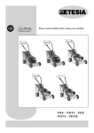
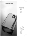
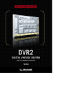
UM0214
User manual
Ambient light sensor demonstration board
Introduction
This user manual, along with the VM6101 datasheet will enable you to evaluate the
VM6101.
Kit contents
●
1 x VM6101 demonstration board
●
Parallel port cable
Order codes
Part number
STV-6101-R01
Figure 1.
June 2006
Description
Demonstration board
Demonstration board
Rev 1
1/9
www.st.com
Hardware
UM0214
1
Hardware
1.1
Demonstration board
Figure 2.
Demonstration board schematic
2/9
UM0214
1.2
Hardware
Bill of materials
Table 1.
Demonstration board BOM
Reference
Description
Manufacturer
Part number
U1
Ambient light sensor
STMicroelectronics VM6101V008
D1
Red Led - surface mount
Standard component - many suppliers
C1
1uF Ceramic Capacitor
Standard component - many suppliers
R1,R2
4K7 I2C pullup resistors
Standard component - many suppliers
R5
1K5 Resistor
Standard component - many suppliers
R3,R4
Not fitted (device address selection
pullup/down resistors)
Standard component - many suppliers
3/9
Software
UM0214
2
Software
2.1
Installation
1.
Check that the user logged on has Administrator rights for the PC/Laptop that is being
used. This can be verified by checking the User Accounts (Start: Settings/Control
Panel/User Accounts)
If administrator rights are not enabled, please see local network administrator to enable
them as they must be enabled for software to operate corrrectly.
2.
Check that the PC/Laptop has the parallel port configured as ECP. This can be verified
using Device Manager (Start: Settings/Control Panel/System/Hardware/Device
Manager)
Figure 3.
Parallel port setting in device manager
If the Parallel Port is not set up as ECP, then you will need to change it in the BIOS settings.
PC / LAPTOP CONFIGURATION:
a)
Power on the PC / Laptop and enter the BIOS setup
b)
Go into the Integrated Devices menu -> Parallel Port
c)
The parallel port settings should be changed to:
d)
4/9
Parallel Port
Enabled
Mode
ECP
Base I/O Address
378H
Interrupt
IRQ 7
DMA
DMA Off
Save and Exit
3.
Install the v2wreg driver by double clicking on the InstV2W.exe icon and follow the
commands given by the installation wizard.(a)
4.
Copy across the ‘VM6101_DEMO_release_v*.*.exe’(b) and the ‘VM6101_ACQ.exe’
applications to a suitable location (for example C:\VM6101).
UM0214
2.2
Software
Connection
1.
Connect VM6101 demo board to the parallel port via the cable supplied.
2.
Open VM6101_Demo application by double clicking on it.
3.
If an initial connection error occurs and the software cannot connect to the hardware
the following error message is displayed:
Figure 4.
Connection error
If this error is seen make sure the cable is properly connected to the demo board and
parallel port. Hit retry to try to connect again.
If this error message continually occurs there could be a problem with the BIOS settings so
these should be checked, then the above steps followed again. If the error still occurs a
hardware change is needed.
4.
Once a connection is established the following screen should be displayed:
a. To install the software required, you will need Administrator rights on the PC.
b. The latest version should always be used. For example ‘VM6101_DEMO_release_v2.3.exe’
5/9
Software
UM0214
Figure 5.
VM6101 demo app dialog
2.3
Demo application options
Start/stop
This button starts/stops the demo, on start the Y bars shows each of the pixel's activity.
Exit
This button closes down the application.
About
This button shows the version information.
Output type
The user can select either Threshold or PWM (Pulse Width Modulation). The default is
Threshold and therefore the threshold options are shown in the group below (see Figure 5).
When PWM is selected this group changes to the PWM options. See Figure 6.
6/9
UM0214
Software
Figure 6.
PWM option
Threshold
The Threshold options include upper and lower threshold setting with Greater Than / Less
Than tick boxes for these thresholds and Active High / Low Output.
The default is for the Upper Threshold to be set to 19.531 W/m2 with the Less Than box
ticked (as shown in Figure 5), the output is set to Active High. In this mode the LED on the
demo board should be on in normal "office" lighting conditions.
When the user hits the START button the LED output will be mimicked by the Threshold
Indication box which will turn yellow when the LED is on. If the threshold is crossed the LED
on the demo board turns off. If the output is changed to Active Low the LED (and threshold
indication box) the output is inverted (i.e. the LED will turn on if the threshold is crossed).
The user can set the thresholds by hitting the SET button beside the relevant threshold. This
will set the threshold to the current light level experienced by the sensor when the button is
hit.
Note:
The Thresholds can only be set when the demo app is running.
The thresholds are activated using the tick boxes, that is the threshold is only activated
when the < or > for that threshold is ticked. The user can deactivate a threshold by
deselecting the ticks.
PWM
When the Output Type is changed to PWM the Sensitivity and Frequency options are
displayed as shown in Figure 6.
The Sensitivity and Frequency can be changed by using the slider and drop down menu.
Units
The units displayed in the Y Bar outputs can be changed by using the drop down menu
beside the About button. This will change the units that are displayed in the box under the
pixel's light bar and also change the displayed value of any thresholds that are set.
7/9
Revision history
3
UM0214
Revision history
Table 2.
8/9
Document revision history
Date
Revision
5-Jun-2006
1
Changes
Initial release.
UM0214
Please Read Carefully:
Information in this document is provided solely in connection with ST products. STMicroelectronics NV and its subsidiaries (“ST”) reserve the
right to make changes, corrections, modifications or improvements, to this document, and the products and services described herein at any
time, without notice.
All ST products are sold pursuant to ST’s terms and conditions of sale.
Purchasers are solely responsible for the choice, selection and use of the ST products and services described herein, and ST assumes no
liability whatsoever relating to the choice, selection or use of the ST products and services described herein.
No license, express or implied, by estoppel or otherwise, to any intellectual property rights is granted under this document. If any part of this
document refers to any third party products or services it shall not be deemed a license grant by ST for the use of such third party products
or services, or any intellectual property contained therein or considered as a warranty covering the use in any manner whatsoever of such
third party products or services or any intellectual property contained therein.
UNLESS OTHERWISE SET FORTH IN ST’S TERMS AND CONDITIONS OF SALE ST DISCLAIMS ANY EXPRESS OR IMPLIED
WARRANTY WITH RESPECT TO THE USE AND/OR SALE OF ST PRODUCTS INCLUDING WITHOUT LIMITATION IMPLIED
WARRANTIES OF MERCHANTABILITY, FITNESS FOR A PARTICULAR PURPOSE (AND THEIR EQUIVALENTS UNDER THE LAWS
OF ANY JURISDICTION), OR INFRINGEMENT OF ANY PATENT, COPYRIGHT OR OTHER INTELLECTUAL PROPERTY RIGHT.
UNLESS EXPRESSLY APPROVED IN WRITING BY AN AUTHORIZE REPRESENTATIVE OF ST, ST PRODUCTS ARE NOT DESIGNED,
AUTHORIZED OR WARRANTED FOR USE IN MILITARY, AIR CRAFT, SPACE, LIFE SAVING, OR LIFE SUSTAINING APPLICATIONS,
NOR IN PRODUCTS OR SYSTEMS, WHERE FAILURE OR MALFUNCTION MAY RESULT IN PERSONAL INJURY, DEATH, OR
SEVERE PROPERTY OR ENVIRONMENTAL DAMAGE.
Resale of ST products with provisions different from the statements and/or technical features set forth in this document shall immediately void
any warranty granted by ST for the ST product or service described herein and shall not create or extend in any manner whatsoever, any
liability of ST.
ST and the ST logo are trademarks or registered trademarks of ST in various countries.
Information in this document supersedes and replaces all information previously supplied.
The ST logo is a registered trademark of STMicroelectronics. All other names are the property of their respective owners.
© 2006 STMicroelectronics - All rights reserved
STMicroelectronics group of companies
Australia - Belgium - Brazil - Canada - China - Czech Republic - Finland - France - Germany - Hong Kong - India - Israel - Italy - Japan Malaysia - Malta - Morocco - Singapore - Spain - Sweden - Switzerland - United Kingdom - United States of America
www.st.com
9/9