1
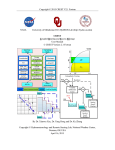
NASA-OU CREST 1.6c README
27 May 2010
(Draft version)
Table of Contents
1. A BRIEF DESCRIPTION OF THE MODEL
3
2. COMPILING ON LINUX
5
2.1 USING “IFORT” COMPILER
2.2 USING “GFORTRAN” COMPILER
5
5
3. COMPILING ON WINDOWS
5
3.1 USING “COMPAQ VISUAL FORTRAN” (CVF) COMPILER
5
4. CONTROL FILE INPUTS
6
4.1 INPUT FILE INFORMATION (PART A)
4.2 SUB-BASIN INFORMATION (PART B)
4.3 RUN TIME INFORMATION (PART C)
4.4 PARAMETER SETTINGS (PART D)
4.5 BASIN OUTLETS (PART E)
4.6 CALIBRATION SETTINGS (PART F)
4.7 GRID OUTPUTS (PART G)
4.8 RETURN PERIOD ANALYSIS (PART H)
4.9 END OF CONTROL FILE (PART I)
6
7
7
8
10
10
11
11
12
5. INPUTS
12
5.1 BASIC GRIDS
5.2 RAIN (QPE) INPUTS
5.3 PET INPUTS
12
12
13
6. RUN STYLES
13
6.1 SIMULATION
6.1.1 RUNNING IN SIMULATION MODE
6.1.2 SIMULATION MODE STANDARD OUTPUT
6.1.3 SIMULATION MODE FILE OUTPUT
6.2 AUTOMATIC CALIBRATION
6.2.1 RUNNING IN AUTOMATIC CALIBRATION MODE
6.2.2 AUTOMATIC CALIBRATION MODE STANDARD OUTPUT
6.2.3 AUTOMATIC CALIBRATION MODE FILE OUTPUT
6.3 ONLINE MODE
13
13
14
14
15
15
15
16
16
7. IMPLEMENTING OF THE CREST MODEL FOR OTHER BASINS
17
1
8. IMPROVEMENT AND HELP
18
2
1. A Brief Description of the Model
The Coupled Routing and Excess STorage (CREST) distributed hydrological model is a
hybrid modeling strategy that was recently developed by the University of Oklahoma
(http://hydro.ou.edu) and NASA SERVIR Project Team (www.servir.net). CREST simulates the
spatiotemporal variation of water and energy fluxes and storages on a regular grid with the grid
cell resolution being user-defined, thereby enabling global- and regional-scale applications. The
scalability of CREST simulations is accomplished through sub-grid scale representation of soil
moisture storage capacity (using a variable infiltration curve) and runoff generation processes
(using linear reservoirs).
The CREST model was initially developed to provide online global
flood predictions with relatively coarse resolution, but it is also applicable at small scales, such as
single basins. This README file and the accompanying code concentrates on and tests the
model at the small scale. The CREST Model can be forced by gridded potential
evapotranspiration and precipitation datasets such as, satellite-based precipitation estimates,
gridded rain gauge observations, remote sensing platforms such as weather radar, and
quantitative precipitation forecasts from numerical weather prediction models.
The
representation of the primary water fluxes such as infiltration and routing are closely related to
the spatially variable land surface characteristics (i.e., vegetation, soil type, and topography).
The runoff generation component and routing scheme are coupled, thus providing realistic
interactions between atmospheric, land surface, and subsurface water.
3
Fig. 1. Core components of the CREST model: (a) vertical profile of a cell including
rainfall-runoff generation, evapotranspiration, sub-grid cell routing and feedbacks from routing;
(b) variable infiltration curve of a cell; (c) plan view of cells and flow directions; and (d) vertical
profile along several cells including sub-grid cell routing, downstream routing, and subsurface
runoff redistribution from a cell to its downstream cells.
4
2. Compiling on Linux
It is not necessary to modify the source code of CREST in order to change settings or basins.
The control file with a default name of “control.txt” and basic grids dictate the necessary settings
for running the model. The control file name must be in lower case, other wise it may not be
recognized on Linux/Unix operating systems.
2.1 Using “ifort” compiler
Compiling CREST is easy with any Fortran compiler. The source code to CREST is
contained within a single file for ease of use. As such, in order to compile CREST using ifort all
that is needed is a simple command such as "ifort -o crest –assume byterecl -fpp crest1.6.f90"
this will compile the CREST Fortran source code file into an executable named "crest." The Intel
Fortran compiler has many other command line arguments to enable additional optimizations and
other features. For a full list and description of how to use them consult the Intel Fortran compiler
manual.
2.2 Using “gfortran” compiler
The source code to CREST is contained within a single file for ease of use. As such, in
order to compile CREST using gfortran all that is needed is a simple command such as “gfortran
-x f95-cpp-input -o crest -ffree-line-length-none -O3 crest1.6.f90” this will compile the
CREST Fortran source code file into an executable named "crest." The gfortran compiler has
many other command line arguments to enable additional optimizations and other features. For a
full list and description of how to use them consult the gfortran compiler manual.
3. Compiling on Windows
It is not necessary to modify the source code of CREST in order to change settings or basins.
The control file with a default name of “control.txt” and basic grids dictate the necessary settings
for running the model.
3.1 Using “Compaq Visual Fortran” (CVF) compiler
TODO: Write instructions here...
5
4. Control File Inputs
The model's input information is read in through the control file. This file dictates everything
configurable about the way the CREST model operates. This includes input file locations, time
periods over which to run, auto-calibration and output file settings.
There are nine parts to the control file (see example) and separated by a separate line like
"****************************************************************** Part X"
X here varies from A to I.
The other lines have two or more sections. The first section of each line (except separator
line) is an explanation of this line; it can be changed into any other phrase (less than 80 letters) at
the user’s will.
4.1 Input File Information (Part A)
" Project name"
"nzoia"
"
Run Style"
"simu"
"
Basic"
"biffit"
"D:\crest\project\example\"
"
Rain"
"trmmrt"
"D:\crest\project\example\trmmrt\"
"
PET"
"bibimo"
"D:\crest\project\example\bibimo\"
"
Export"
"biffit"
"D:\crest\project\example\export\"
"
Discharge"
"column"
"D:\crest\project\example\nzoia.hyp.txt"
The project name is “nzoia”; it appears in the output filename;
The run style “simu” means simulation; other possible run styles are “cali” (automatic
calibration), “line” (on line mode) and some other debug modes.
Basic line shows the directory to search for DEM (digital elevation model), DDM (drainage
direction map), FAM (flow accumulation map) and some other files; file format is set as “biffit”
(binary format, same size as DEM), another choice is “ascfit” (ASCII format, same size as DEM)
which is compatible to ARCGIS. ASCII format is compatible well between operation systems,
but W/R speed is lower than binary format.
Rain line is the folder of precipitation data, the possible format are “trmmrt” (TRMM real
time raw file), “trmmv6” (TRMM V6 raw file), "nmqbin" (NMQ Binary file), “biffit” and
6
“ascfit”.
PET line is the folder of potential evaporation data, the possible format are “bibimo” (binary
format, bigger than DEM, monthly data), “biffit” and “ascfit”. “bibimo” is global monthly mean
PET data include twelve files.
Export line is the folder of output files, the possible formats are “biffit” and “ascfit”.
Discharge line is the file of observation discharge used in automatic calibration; the file name
can be blank unless the run style is “cali”. The possible format is “column” only.
4.2 Sub-basin Information (Part B)
" Sub basin Num"
1
"
"Null"
Sub basin 1"
Part B is used for basin-based parameter management; it is to be improved and better
documented in a later version.
4.3 Run Time Information (Part C)
"
Time Step"
"
Date Begin"
"h"
3
"2003010100"
"
Date Warm" "2001010100"
"
Date End"
"2003010200"
"no"
"no"
Second section of Time step line is unit of time steps, possible units in time step are “y”
(year), “m” (month), “d” (day), “h” (hour), “u” (minute) and “s” (second). The last section of this
line is the number of time steps. The example here means run the model runs with a 3 hour time
step.
Date format in Date Begin line is defined as “yyyymmddhhuuss”, the length is up to the time
step unit, for example, “yyyy” when time step unit is “y”; “yyyymmddhhuuss” when time step
unit is “s”. The last section of this line is a mark for status reading, “yes” means user want to
run the model by three 2-D status files as initial value, “no” means the initial values are
determined by parameters. The 2-D status files are saved to and read from the Export folder if
this setting is specified as "yes".
7
Date Warm only effective in automatic calibration, difference between simulation and
observation discharge before this date will be omitted. A wrong Date Warm will be corrected
automatically.
Format of Date End line is same as Date Begin line; the last section of this line is a mark for
status writing.
4.4 Parameter Settings (Part D)
In total there are 17 parameters in this version. Each parameter has an abbreviation (the first
section of each line), a minimum value (the second section of each line), a maximum value (the
third section of each line) and a current value (the last section of each line). A “yes” or “no” mark
tells whether optimize its value during automatic calibration. When calibrating the minimum and
maximum values define the search range for each parameter and the current value is not used;
when operating in simulation mode the minimum and maximum values are not used and the
current value is used for the simulation run.
" Parameter Num"
18
"coeM"
1
150
"yes"
107.67186
"expM"
0.2
0.9
"yes"
0.30501
"River"
0.1
3
"yes"
1.129872
"Under"
0.01
1
"yes"
0.869404
"LeakO" 0.1
1
"yes"
0.357427
"LeakI"
0.01
0.5
"yes"
0.119561
"Th"
10
100
"yes"
54.522789
"GM"
0.5
2
"yes"
1.259213
"pWm"
10
500
"yes"
337.073669
0.05
1.5
"yes"
0.961943
"pIM"
0
100
"yes"
8.852914
"pKE"
0.1
3
"yes"
0.387291
"pFc"
1
10
"yes"
6.506332
"iWU"
1
100
"yes"
63.829159
"iSO"
1
10
"yes"
2.040005
"iSU"
1
50
"yes"
26.156597
"pB"
8
"Rain"
0.1
3
"no"
1.0
"AreaC"
0.5
1.5
"no"
1.0
"coeM" refers to the slope flow speed multiplier. (pCoeM internally)
"expM" refers to the slope flow speed exponent. (pExpM internally)
"River" refers to the multiplier used to convert slope flow speed to channel flow speed.
(pCoeR internally)
"Under" refers to the multiplier used to convert slope flow speed to interflow flow speed.
(pCoeS internally)
"LeakO" refers to the overland reservoir discharge multiplier. (PLeaOne internally)
"LeakI" refers to the interflow reservoir discharge multiplier. (PLeaTwo internally)
"Th" refers to the flow accumulation needed for a cell to be marked as a channel cell. If a
cells flow accumulation is greater than Th then the cells slope flow speed is multiplied by River.
The units are km2. (pTh internally)
"GM" refers to the change in DEM used for calculating the slope when the DEM for the
downstream cell is higher than the upstream or the downstream cell is a nodata/outside
region cell. (pGm internally)
"pWm" refers to the maximal soil water capacity (in depth) of three soil layers. (pWmax
internally)
"pB" refers to the exponent of the variable infiltration curve. (pB internally)
"pIm" refers to the Impervious area ratio. This ratio is stored as a percentage between 0 and
100. (pIM internally)
"pKE" refers to the multiplier to convert between input PET and local actual ET. (pKE
internally)
"pFc" refers to the soil saturated hydraulic conductivity. (pFc internally)
"iWU" refers to the initial value of soil water. This is a percentage of the pWm and should
therefore vary between 0 and 100. (pOneW internally)
"iSO" refers to the initial value of overland reservoir. (pOneSto internally)
"iSU" refers to the initial value of interflow reservoir. (pTwoSto internally)
"Rain" refers to the multiplier on the precipitation field.
"AreaC" refers to the multiplier that modifies the area of grid cells. (Used for research and
9
debugging purposes)
4.5 Basin Outlets (Part E)
" Exit Numbers"
1
"RCorLL, ClipRe"
"no"
"no"
"
"gauge"
34.08749
Location"
0.1208334
Currently the maximum number of allowed exits is 255; the name and location of each exit
should be given on separate Location lines.
RCorLL specifies if the exit number is relative to the basic grids (DEM, DDM, FAM) or in
latitude and longitude. A value of “yes” means the location of the exit is a column and row in the
DEM, a value of “no” means the location is longitude and latitude.
If ClipRe is set as “yes”, model will clip the drainage area for the first exit to help user check
the drainage area or set a sub project from current project.
4.6 Calibration Settings (Part F)
"
Min NSCE" 0
" Max BiasP (%)"
100
"
100
"
"
Basic run"
Top N" 10
Criteria"
0.005
An adaptive random search algorithm is nested in CREST.
Min NSCE and Max BiasP (%) are used to screen out good parameters combinations from all
randomly defined parameters combinations.
Basic run is the number of good parameters combinations (which meet the above NSCE and
BiasP scores) to find before adapting the parameter span.
Top N is the number of parameter combinations to keep in order to adapt the parameter span.
Criteria value specifies that the automatic calibration will be finished when difference of
NSCE between top N parameters combinations is less than this value.
10
4.7 Grid Outputs (Part G)
Part G is control of 2-D grid-based output, “yes” means output and “no” means do not output.
The run time of the model depends on the number of outputs. A faster CREST model runtime can
be achieved by reducing the number of outputs. Output format is controlled by the Export format
in part A (see Section 4.1). All outputs are spatially interpolated to the proper resolution and
clipped to either the basic grids or the drainage area depending on the setting of ClipRe in Part E
(Section 4.5).
"
"
Rain"
"no"
PET" "no"
"
actE"
"no"
"
Runoff"
"no"
"
Soil"
"no"
"
OneExc" "no"
"
TwoExc" "no"
"
OneSto" "no"
"
TwoSto" "no"
Rain is the input precipitation; unit is mm/hour.
PET is the input PET; unit is mm/hour.
actE is the depth of simulated actual evapotranspiration; unit is mm/hour.
Runoff is the simulated discharge of each grid cell; unit is m³/s.
Soil is the depth of water filling the pore space bucket "pWm"; unit is mm. This is also the
“OneW” status output.
OneExc is the depth of surface excess rain; unit is mm/hour.
TwoExc is depth of interflow excess rain; unit is mm/hour.
OneSto is depth of overland reservoir; unit is mm/hour.
TwoSto id depth of interflow reservoir depth; unit is mm/hour.
4.8 Return Period Analysis (Part H)
Part H is control of flood level on grid based return period analysis. It’s not available in this
11
example.
"
Level Num "
"
Level Mark"
0
4.9 End of Control File (Part I)
Part I is an end of control file marker, the model will not read in anything after this part, this
means the user can add comments after this line:
"End Mark Check"
"eof"
5. Inputs
5.1 Basic Grids
The DEM (digital elevation model), DDM (drainage direction map), FAM (flow
accumulation map) are the basic grids which define the region over which CREST will be able to
model.
These can be derived using the supplied CNT Tool for sub-regions of the globe. The CNT
Tool is able to resample and interpolate to any desired cell size for any user-defined region of the
globe. All that is needed to use this tool is a bounding rectangle defined in terms of latitudes and
longitudes for the region you wish to model.
5.2 Rain (QPE) Inputs
The rain input is one of two input forcings for the CREST model. Currently several input
formats can be read by the CREST model. The formats and features are summarized in the table
below.
Format
Generic
Match
Units
Naming Convention
Basic
Grids
No
No
mm/timemark
3B42RT. yyyymmddhh.6A.bin
trmmrt
No
No
mm/timemark
3B42.yymmddhhdd.6A.HDF
trmmv6
No
No
mm/timemark
1HRAD.HSR.
yyyymmdd.hh00
nmqbin
Yes
Yes
mm/timemark
yyyymmddhhuuss.txt
ascfit
Yes
No
mm/timemark
yyyymmddhhuuss.txt
ascbig
Yes
Yes
mm/timemark
yyyymmddhhuuss.bif
biffit
12
5.3 PET Inputs
The Potential Evapotranspiration (PET) is the second input forcing for the CREST model.
6. Run Styles
Different run styles have different possible outputs; the table below lists possible outputs for
each run style:
2-D Output
Regional Mean Values
Reads Status Files
Writes Status Files
Parameter Combinations
simu
cali
online
Yes
One
Yes
Yes
No
No
Multiple
Yes
No
Yes
Yes
One
Automatically
Automatically
No
6.1 Simulation
6.1.1 Running in Simulation Mode
To run the model in simulation mode the run style in the control file must be set to "simu".
Precipitation data and PET data are also needed for the simulation period. By default CREST
reads the control file called "control.txt" located in the current working directory. However, as of
CREST 1.6c it is possible to specify the control file name as a command line option to the
CREST executable.
13
6.1.2 Simulation Mode Standard Output
The first line is model version message.
The second line includes Exit Name, Col, Row, Longitude, Latitude and total drainage grids,
The third line is name of first exit and its simulated drainage area from DEM and DDM.
The third line is name of kernel model used here (combination of rainfall-runoff and routing
models)
The last but one line is statistic (NSCE and BiasP) between simulation in first exit and
observation.
The last line is a succeed mark
The others are information of each step following rules of “no message means good
message”.
6.1.3 Simulation Mode File Output
Besides any possible 2-D files, one file in export folder will be found after run the model in
“simu”; the name is defined as: “Project name”.“simu”.“finished time”.“txt”, like file
“nzoia.Simu.20091130155202.txt” in the example.
It’s a time series of regional mean values
include eleven or more columns: Date, Rain, PET, actE, Soil, OneExc, TwoExc, OneSto, TwoSto,
nzoia, Gauge.
The first column Date is date and time, the format is defined as “yyyymmddhhuuss”, the
length is determined by time step unit (see Section 4.3).
14
The last column Gauge is from observation discharge. CREST will not do any temporal
interpolation for discharge data, missing data is marked as “-1”.
Meaning of other columns is similar to what is defined in Section 4.7.
Column nzoia is the simulated discharge at the exit grid, the number and location is defined
part E (Section 4.5).
6.2 Automatic Calibration
6.2.1 Running in Automatic Calibration Mode
To run the model in automatic calibration mode the run style in the control file must be
set to "cali". Precipitation data, PET data and observed discharge (Section 4.1, Discharge) are
also needed for the calibration period. Resumption of calibration has been implemented in
CREST v1.6b. A saved information file called "savedParams.cali" is written to the Export folder
and will be read automatically on calibration startup if it exists.
6.2.2 Automatic Calibration Mode Standard Output
The first line is model version message.
The second line includes Exit Name, Col, Row, Longitude, Latitude and total drainage grids.
Lines after that is finished time of each run following a run number. Once CREST found any
good parameters combinations, it will show you the index, NSCE, BiasP and gap of top N good
15
results.
6.2.3 Automatic Calibration Mode File Output
In “cali” model, the model will not output any 2-D files automatically. One specially output
is named “Project name”.“cali”.“begin time”.“txt”, such as “nzoia.Cali.20091130155417.txt”. the
file include 21 columns, NSCE, Bias, 17 Parameters, Index, Run Num.
NSCE and Bias are statistic values between discharge of the first exit (see Section 4.5) and
observation
17 Parameters are 17 separate columns list the parameter values.
Index is a number of good parameters combinations.
Run Num is total number of runs before found that good parameters combinations. It can be
used in the appraising the parameter setting of your automatic calibration.
If automatic calibration is finished without any problem, the top N parameters combinations
will be added into the end of this file.
Besides that file, there also some other outputs named “Project name”.“cali”.“begin time”.
“Index”.“txt”, such as “nzoia.Cali.20091130155417.3826.txt”. The format of these files are same
as in Section 6.1.3.
6.3 Online mode
In online mode, CREST will scan the latest precipitation file from now as the Date End, and
the latest status file from the found Date End as the Date Begin.
If user defined the Date End in
control file earlier than present in purpose, the model will scan from that earlier time. If used in
any project with predicted precipitation, we need change the code.
If no new precipitation file
has been found, the model will terminate. If no old status file has been found, the model will run
from Date Begin defined in control file.
There is one main output in online mode named “Project name”.“line”.“txt”, such as
“nzoia.Line.txt”. The format of this file is same as Chapter 4.1. New result will be appended into
this file, and make it same as from one run.
Status files are very important to connecting different runs; each run will generate three
status files once one or more precipitation files have been detected. Status files are named as
16
“Project name”.“Status”.“date and time”.“OneW/OneSto/TwoSto”.“bif”, they are compressed
binary file such as “nzoia.Status.2003011100.OneW.bif”.
Online run need regular maintenance to clean old status files, the frequency is up to your
storage.
7. Implementing of the CREST model for other basins
The CREST model automatically runs over the region defined by the basic grid files.
Therefore if you are operating with global basic grids it is possible easily and quickly model an
basin in the world by defining a new basin outlet as described in Section 4.5. In the event that the
basic grids you are using do not cover the region which you want to model or if you want to
model a region with a finer resolution then it is necessary to derive new basic grids. The steps to
do this are described below.
Fully implementing the CREST model on any basin can be achieved in a three step process:
1. To implement the CREST model on another basin it is first necessary to derive the
basic grids for the new basin region.
a.
Determine the latitudes and longitudes of a rectangle around the region
which you wish to model. These do not have to be precise by any means and
can be pulled from Google Earth or Google Maps for an approximate region
around the basin you wish to model. The basin you wish the model on must
be entirely contained inside the bounding rectangle you specify however.
b. Derive the basic grids (DEM, DDM, FAM) using the supplied CNT Tool.
2. A control file for the new modeling region needs to be created.
a. Copy an existing control file (even one of the provided example control files)
and modify the paths to point to the location of the new basic grids.
b. It is likely that the CNT Tool produced DEM, DDM, and FAM grids that were
NOT named appropriately. In order for CREST to work with the DEM, DDM
and FAM files produced by the CNT Tool they must be named DEM.txt,
DDM.txt and FAM.txt. It is important to change the file format in the control
file for the basic grids to "ascfit" (see Section 4.1 for more details). After the
initial run with the newly provided ascii basic grids CREST will produce bif
binary grids. At this point the file format in the control file for the basic grids
17
can be changed to "biffit" for faster model spinup times.
c. At this point new basin outlets inside the modeling region can be defined as
described in Section 4.5.
3.
The model can now be run for your new basin in any desired mode. To get realistic
results it is necessary to calibrate the model using a gauged station located near your
new basin's outlet. The automatic calibration built into the CREST model is the
easiest way to calibrate the model.
8. Improvement and help
Future work:
Fix the bug when using gfortran compiler
Improve the date manage engine
Fix bugs in automatic calibration output
Enhance performance for peak automatic calibration
Improve routing subroutine for future possible upgrade
Improve basin based parameter management.
Development and maintenance of the current official version of the NASA-OU CREST
model is conducted at the University of Oklahoma, Remote Sensing and Hydrology Research
Group (http://hydro.ou.edu) and Center for Natural Hazard and Disaster Research located in
National Weather Center (http://nwc.ou.edu). For information about the current release of the
CREST model or to get the source code for beta versions of releases under development, send
e-mail to [email protected] and include "CREST Model" in the subject line.
18