1
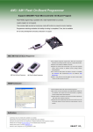
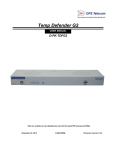
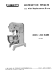
AMOBP Commander
Users Manual
OBJECT Co.,Ltd.
PanaXSeries and DebugFactory are trademarks of Panasonic Corporation.
WINDOWS are trademarks of Microsoft Corporation.
Adobe Acrobat Reader is a trademark of Adobe Corporation.
The other corporation name, logotype, and product names written in the book are trademarks or registered
trademarks of their corresponding corporations.
Request for your special attention and precautions in using the technical information and
semiconductors described in this book
(1) An export permit needs to be obtained from the competent authorities of the Japanese Government if any of the
products or technologies described in the book and controlled under the “Foreign Exchange and Foreign Trade
Law” is to be exported or taken out of Japan.
(2) The contents of this book are subject to change without notice in matters of improved function.
(3) We are not liable for any damages arising out of the use of the contents of this book, or for any infringement of
patents or other rights owned by a third party.
(4) No part of this book may be reprinted or reproduced by any means without written permission from our company.
(5) In no event will OBJECT and Panasonic Corporation. Semiconductor Company be liable to you for any indirect
damages caused by using this Product.
(6) In the event that you find a defect of this Product and advise OBJECT of it within 6 month from the date of
purchase, OBJECT will pay for the damage. In no event OBJECT's liability to you exceed the amount actually
paid by you for this Product, and as the previous article, OBJECT and Panasonic Corporation. Semiconductor
Company shall not be liable to you for defect warranty.
( 7 ) We can supply the support for AMOBP Commander via E-Mail ([email protected]) and WEB SITE
(http://www.OBJECT.jp) Please determine the up- to-date information and more on our WEB SITE.
AMOBP Commander Users Manual
- Contents [1] Introduction .................................................................. 4
1.1 Overview ..................................................................... 4
1.2 Support PC/OS ................................................................ 4
1.3 On-board Programming Functions ............................................... 4
1.4 Support Microcomputer ........................................................ 4
[2] Set Up ........................................................................ 5
2.1 Installing AMOBP Commander ................................................... 5
2.2 Installing the USB driver .................................................... 8
2.3 Installing the Device Package ................................................ 10
2.4 Uninstalling ................................................................. 11
[3] AMOBP Commander ............................................................... 12
3.1 Main Tab ..................................................................... 13
3.2 Dump Tab ..................................................................... 15
3.3 CPU Tab ...................................................................... 16
3.4 CPU Tab(UART version) ........................................................ 19
3.5 Security Tab ................................................................. 20
3.6 Option Tab ................................................................... 23
3.7 Store Tab .................................................................... 24
3.8 About Tab .................................................................... 25
[4] Secure Support by Keycode ..................................................... 26
4.1 Keycode Type ................................................................. 26
4.2 Keycode File ................................................................. 27
[5] UART version specification .................................................... 28
5.1 Interface standard ........................................................... 28
5.2 Target system action condition ............................................... 28
5.3 Boot program ................................................................. 28
5.4 Negotiation .................................................................. 29
5.5 Baud rate setting ............................................................ 29
[6] Offline mode .................................................................. 30
6.1 Store ........................................................................ 30
6.2 Connection with a target system .............................................. 30
6.3 Program ...................................................................... 30
[7] Error/Warning Message ......................................................... 31
[8] Index ......................................................................... 38
-3- Microcomputer Research & Development OBJECT Co., Ltd. http:// http://www.OBJECT.jp/
AMOBP Commander Users Manual
[1] Introduction
1.1 Overview
AMOBP Commander is control software corresponding to AM On-Board Programmer Type1, AM On-Board
Programmer Type2 and AMOT.
1.2 Support PC/OS
- Basic configuration································IBM-PC and the compatible machine that implement USB1.1 and operate
within Windows environment
- CPU ·····················································Pentium2 233MHz and over (Recommended: Pentium2 400MHz and over)
- Memory space·······································128MB and over (Recommended: 512MB and over)
- HDD free space·····································20MB and over (Recommended: 40MB and over)
- OS ·························································Microsoft WindowsXP(After SP2.)
Microsoft WindowsVista
Microsoft Windows7
1.3 On-board Programming Functions
- Writing
- Reading
- Erasing
- Verifying
- Protecting
- Creating and editing the security key
- Off-line operation
1.4 Support Microcomputer
The following support list includes future devices. Please confirm latest support information on our company WEB site
(http://www.OBJECT.jp/).
AM1(MN101C)
AM1(MN101E)
AM3(MN103S)
MN101CF73A,MN101CF77G(*1),MN101CF78A,MN101CF91D,MN101CF93K
MN101CF95G,MN101CF97D,MN101CFA7D,MN101CFB6G,MN101CFD0G
MN101EF16K,MN101EF16N,MN101EF16Z,MN101EF29G,MN101EF30R,MN101EF31G
MN101EF32D,MN101EF33N,MN101EF34D,MN101EF35A,MN101EF35D,MN101EF46R
MN101EF49N,MN101EF50D,MN101EF51A,MN101EF57G,MN101EF60D,MN101EF63G
MN101EF76K,MN101EF77G
MN103SF73N,MN103SF73R,MN103SF77R,MN103SFA5K,MN103SFA7K,MN103SFB5K
MN103SFC2D,MN103SFC6K,MN103SFE3K,MN103SFE4G,MN103SFE4K,MN103SFG5K
MN103SFH7J,MN103SFJ9D,MN103SFK0K,MN103SFK1K
March, 2011. *1:AMOT does not support.
-4- Microcomputer Research & Development -
OBJECT Co., Ltd. http:// http://www.OBJECT.jp/
AMOBP Commander Users Manual
[2] Set Up
2.1 Installing AMOBP Commander
To use AM On-Board Programmer, start up the installer (AMOBP_Setup.exe) in the included CD-ROM and install
AMOBP Commander into your PC.
[Installing Procedure]
(1) Check precautions
Read the text file Readme_E.txt on the included CD-ROM. This file contains updated information that may not be
included in each manual.
(2) Install the software
Start the installer (AMOBP_Setup.exe) on the included CD-ROM and install by following dialog messages.
[NOTE!]
The installation is by default "%system%\Program Files\OBJECT\AMOBP Commander".
"%system%" is a system disk of Windows. It is "C:" in a general IBM/PC i386 system
STEP1
The following is the AMOBP_Setup.exe setup screen. Choose language and click “OK”.
STEP2
The following is the AMOBP_Setup.exe setup screen. Click “OK”.
-5- Microcomputer Research & Development OBJECT Co., Ltd. http:// http://www.OBJECT.jp/
AMOBP Commander Users Manual
STEP3
Read the license agreement carefully. If you accept all terms of the agreement, click the “Yes(Y)" button.
STEP4
Select the folder in which the files should installed. When installing them into the default folder, click on the “Next”
button. When changing the installing folder, click on the “Browse…” button and specify the folder.
STEP5
Specify the folder name to be added to the “program” menu on the start menu. When changing the folder name, enter
any name to the “Program folder (P)” column. When selecting the default folder, click the “Next(N)” button.
-6- Microcomputer Research & Development -
OBJECT Co., Ltd. http:// http://www.OBJECT.jp/
AMOBP Commander Users Manual
STEP6
After the install file is finished coping, the set up finished dialog will appear, and click on the “Finish” button to end the
setup.
-7- Microcomputer Research & Development OBJECT Co., Ltd. http:// http://www.OBJECT.jp/
AMOBP Commander Users Manual
2.2 Installing the USB driver
The Windows system asks for driver installation when connecting AM On-Board Programmer to the PC via the
included USB cable. Install the driver by following the steps shown below.
STEP1
When connecting AM On-Board Programmer to the PC via the included USB cable, the following dialog appears.
Check the “No, not this time” check box and click on the “Next(N)” button.
STEP2
Check the “Install from a list or specific location [Advanced]” check box and click on the “Next(N)” button in the
following dialog.
-8- Microcomputer Research & Development -
OBJECT Co., Ltd. http:// http://www.OBJECT.jp/
AMOBP Commander Users Manual
STEP3
As specifing the directory path of the driver file, check the “Search for the best driver in these locations (S)” and
“Include this location in the serarch” box, and click on the “Browse” button to specify the following file. After completing
input, click on the “Next ” button and then searching the driver will start.
Please set folder "Driver" of the attached CD-ROM.
Attention:A warning dialogue is output during driver installation, but I click " Continue Anyway", and please continue
installing it.
STEP4
After the driver file is finished coping, the setup finished dialog will appear, and click on the “Finish” button to end the
driver installation.
-9- Microcomputer Research & Development OBJECT Co., Ltd. http:// http://www.OBJECT.jp/
AMOBP Commander Users Manual
2.3 Installing the Device Package
AM On-Board Programmer Expands supported devices by installing the software packaged in each corresponding
device. Install the software for your device type after installingAMOBP Commander. This section describes how to
install the software using the MN101EF31G package.
* Note : Must install AMOBP Commander before installing the software for the device type. Moreover, please adding the device
package must operate recognizing serial of AM On-Board Programmer and choose "Add keycode" by starting the device
package installer again and register the cereal when two or more main bodies of AM On-Board Programmer are used.
STEP1
Start up the device package installer (AMOBP_MN101EF31G.exe) in the included CD-ROM and install by following
the dialog messages. The serial number of AM On-Board Programmer and the product key of the software for
MN101EF31G are required for installation. The product key is included in the software.
STEP2
Read the license agreement carefully. If you accept all terms of the agreement, click on the “Yes(Y)" button.
- 10 - Microcomputer Research & Development -
OBJECT Co., Ltd. http:// http://www.OBJECT.jp/
AMOBP Commander Users Manual
STEP3
Input the lower 8 digits of the serial number of AM On-Board Programmer(OBPU-DW8/OBPU-DW32)and the 16 bit
product key of the device package and, click on the “Next(N)”.
* Note : Please input only a serial number in the case of use in AMOT.
STEP4
After the install file is finished coping, the set up finished dialog will appear, and click on the “Finish” button to end the
set up.
2.4 Uninstalling
In order to uninstall the AM On-Board Programmer, restart the installer from the included CD-ROM, check the “delete”
check box.
In order to delete the USB driver, open the “system” menu on the Windows control panel, select the “USB
(UniversalSerialBus) controller” in the “device manager” of the hardware tab, and delete AM1 On-Board Programmer
DWire USB I/F or AM3 On-Board Programmer DWire USB I/F.
- 11 - Microcomputer Research & Development OBJECT Co., Ltd. http:// http://www.OBJECT.jp/
AMOBP Commander Users Manual
[3] AMOBP Commander
AM On-Board Programmer is controlled from AMOBP Commander operating in the host PC. AMOBP Commander is
composed of 6 tabs: Main, Dump, CPU, Security, Option, and About. AMOBP Commander has the ROM image
memory. It reads and writes with the Flash ROM of the target microcomputer through the ROM image memory.
[Standard programming procedure]
1. Select the device in the CPU tab and the sector to be programmed.
2. Load the existing keycode in the Security tab.
3. Program on the Main tab.
ROM command
Function tab
File command
Run button
Check sum
Command log
Target I/F type
Device name
Progress bar
- 12 - Microcomputer Research & Development -
OBJECT Co., Ltd. http:// http://www.OBJECT.jp/
Exit button
AMOBP Commander Users Manual
3.1 Main Tab
The Main tab is a command set tab which executes a command to the Flash ROM of the microcomputer, loads ROM
data from the file and saves to the file. “Key” in each command button description is a short-cut key.
ROM read
ROM verify
ROM sector erase
ROM erase
Erase, Program,
verify
collective
execution
(1)
(2)
(3) (5)
(7)
(4) (6)
(8)
(10)
(9)
ROM End address
ROM erase check
File name box
Command halt
ROM Start
address
ROM write
(11)
(13)
(14)
Load file dialog
(12)
Save File
(15)
Load File
(16)
Program run
Check sum
(1) E.P.V. (Erase+Program+Verify) [F3]
The E.P.V button executes erase ROM, program and verifying.
(2) Break [ESC]
Break button. Clicking on the Break button halts the command under execution. Check the log window for the
execution result of the halted command.
(3) Read [F8]
The Read button is used to read data from the Flash ROM. Specify the read range in the CPU tab.
(4) Erase [F5]
The Erase is used to erase the contents of the Flash ROM. Specify the erase range in the CPU tab.
(5) Verify [F7]
The Verify button is used to compare the contents of the Flash ROM with those of AMOBP Commander ROM image
memory.
(6) Chip Erase [F2]
Clicking on the Chip Erase button erases all except the protect sector of the Flash ROM. The Break command is not
acceptable during this command execution.
(7) Erase Check [F6]
The Erase Check button is used to check whether the Flash ROM is erased. Specify the check range in the CPU tab.
(8) Program [F4]
The Program writes the contents of the AMOBP Commander ROM image memory to the Flash ROM.
- 13 - Microcomputer Research & Development OBJECT Co., Ltd. http:// http://www.OBJECT.jp/
AMOBP Commander Users Manual
(9) Filename
The Filename is used to enter the file name used for loading from the file to the ROM image memory of AMOBP
Commander and saving. It has a pull-down history function. Up to 8 past filenames, including PATH, are saved from
the latest one.
(10) Load Dialog
Clicking on the Load Dialog button opens the dialog to specify the file to be read in the ROM image memory of
AMOBP Commander.
(11) Start Address
The Start Address is used to set the start address of the AMOBP Commander ROM image memory used when the file
is saved (SaveAs) and when the binary file is loaded.
(12) End Address
The End Address is used to set the end address of the AMOBP Commander ROM image memory used when the file
is saved (SaveAs).
(13) Load [F9]
Clicking on the Load button allows to read the file specified by the Filename into the ROM image memory of AMOBP
Commander. When the Filename is blank, the file specification dialog will be open. The file format which can be
loaded is 5 types: HEX, S, EF, EX and BIN.
(14) Save As [F10]
The SaveAs is used to save the contents of the AMOBP Commander ROM image memory to the file specified by the
Filename. When the Filename is blank, the file specification dialog will be open. The file format which can be loaded is
4 types: HEX, S, EF and BIN.
(15) CheckSum [Access/Sector]
SectorCheckSum is checksum of the content of ROM image memory of AMOBP Commander checked in CPU
tab. When the loading command is executed and flash ROM is led, it is updated.
AccessCheckSum is checksum when the data transfer (Write and Read) to flash ROM is generated. When the Verify
command execution ends the Program command and the Read command, it is updated.
(16) Run
This button gives a reset pulse for a microcomputer, and it is execute.
- 14 - Microcomputer Research & Development -
OBJECT Co., Ltd. http:// http://www.OBJECT.jp/
AMOBP Commander Users Manual
3.2 Dump Tab
The Dump tab displays and edits the contents of the AMOBP Commander ROM image memory. It can write data at
any address in hexadecimal, but cannot insert, delete or replace data.
ROM dump
Edit enable
check
Jump address
Jump button
Check sum of all
memory
- 15 - Microcomputer Research & Development OBJECT Co., Ltd. http:// http://www.OBJECT.jp/
AMOBP Commander Users Manual
3.3 CPU Tab
The CPU tab sets the sector accessing the device which connects AMOBP Commander. When AMOBP Commander
accesses the built-in Flash of the microcomputer, it accesses only the sector which is sector-checked on the CPU tab.
Select all
ON/OFF
Device
selection
(3)
(4)
(10)
(5)
Sector select
check
Protect check
Device type
information
(6)
(1) (2)
Help for each
device
CPU clock
(7)
Dwire
communication
clock
(8)
(9)
Write protect
Read protect
information
(1) Sector Check
The Sector Check is used to set the sector of the Flash ROM which writes and reads.
(2) Protect Check
The Protect Check is used to set the sector which enables the protecting of the Flash ROM. (Corresponding device
type only)
Write protect is executed by the Program command in the Main tab or the Protect Write command.
[NOTE!]
Protection can be established only once to the sector. It isn't possible to make the established protection release and invalidity, so
please be careful.
(3) Select All ON/OFF
The Select All button is used to set all-ON/OFF in all sector selection checks. “all-selected” and “all-unselected” are
toggled every time pressing this button.
- 16 - Microcomputer Research & Development -
OBJECT Co., Ltd. http:// http://www.OBJECT.jp/
AMOBP Commander Users Manual
(4) Device Selection Menu
This is a pull-down menu for device selection. When installing the device package, the device will be added to the
menu.
An indicated microcomputer kind name is expressing the correspondence range and an interface system to the kind
name as follows continuously.
There is no indication in a correspondence area by the kind with which a BOOT area isn't being supported.
MN101EF31G U_Com
Correspondence area
None : User area
U : User area
B : Boot area
Interface type
Non : DWire
_Com : UART
(5) Device Information Display
Clicking this button displays information such as the memory map of the device in the different window.
- 17 - Microcomputer Research & Development OBJECT Co., Ltd. http:// http://www.OBJECT.jp/
AMOBP Commander Users Manual
(6) CPU Clock Selection Menu
This is a pull-down menu to set the operation clock of the microcomputer.
(7) DWire Clock Selection Menu
This is a pull-down menu to set the DWire clock which communicates with the microcomputer.
(8) Sector Protect Information Read
Clicking on this button reads the protect information which has been set in the microcomputer. (Corresponding device
type only)
The read information is reflected in the sector selection part.
(9) Sector Protect Write
Clicking on the Sector Protect Write button writes protect in the microcomputer by following the sector protect
specified in sector selection. (Corresponding device type only)
[NOTE!]
Protection can be established only once to the sector. It isn't possible to make the established protection release and invalidity, so
please be careful.
(10) Help Display
The Help Display button displays help about the device package.
- 18 - Microcomputer Research & Development -
OBJECT Co., Ltd. http:// http://www.OBJECT.jp/
AMOBP Commander Users Manual
3.4 CPU Tab(UART version)
(13)
CPU clock
measurement
(11)
(12)
HOST PC Serial port
select
Baud rate select
(11) HOST PC serial port select
In the connection to the UART version, the serial port number used with HOST PC is selected. This pull-down menu
does the serial port with which HOST PC that operates AMOBP Commander is equipped and listing is done by the
automatic operation.
(12) Baud rate select
In the connection to the UART version, the baud rate of the serial port used with HOST PC is selected. The baud rate
that can be selected is from 1200bps to 230400bps it, and AUTO. The negotiation cannot be likely to be done
according to the clock of the target microcomputer though do the self adjustment of the target microcomputer with the
baud rate and the velocity baud rate is set automatically when AUTO is selected by a proper baud rate. Moreover, the
baud rate that cannot be set with PC used might not be displayed in the pull-down list of the manual setting.
(13) CPU clock measurement
In the connection to the UART version, The clock of target CPU is measured when this "Negotiation Enable" is
checked when the baud rate is a manual setting and the error margin with the manual setting is detected. However,
when the reliability of the manual setting is high, the negotiation time until the communication beginning can be
shortened by removing this check because the measurement time of a few seconds is needed for this operation.
- 19 - Microcomputer Research & Development OBJECT Co., Ltd. http:// http://www.OBJECT.jp/
AMOBP Commander Users Manual
3.5 Security Tab
The Security tab sets and edits the security keycode. AMOBP Commander has the keycode image memory and
controls the security with the target microcomputer using the contents of the keycode image memory.
There is 2 kinds of method in a keycode. "Write data method" which can set a keycode area, and "Dedicated area
method" for which an exclusive keycode area is used. This type depends on kind of microcomputers.
3.5.1 Dedicated area method (Secure on Chip)
An established exclusive keycode area is used for built-in flash ROM of a microcomputer.
It's possible to write a keycode area in only once. This keycode can't be made erase and invalidity.
When establishing a keycode, please be sure to designate a keycode file. When not understanding a keycode,
reading, rewriting and erasure including ChipErase can't also be done any more, so please be careful.
Keycode dump
display
(1)
Edit enable
check
(2)
Keycode filename
(4)
(3)
(5)
(6)
(7)
(8)
Keycode type
Keycode file
Dialog
Keycode save
Keycode load
Keycode write
(1) Keycode Dump Display
This dump-displays the contents of the keycode image memory on AMOBP Commander. It can edit at the binary.
(2) Edit enable check
Edit of a keycode image memory is permitted. But, only the secure on chip type.
(3) Keycode Filename
The Keycode Filename is used to enter the filename used for loading from the file to the ROM image memory of
AMOBP Commander and saving. It has a pull-down history function. Up to 10 past filenames, including PATH, are
saved from the latest one.
(4) Keycode File Dialog
Clicking the Dialog button displays the dialog window to specify a file to be read into the keycode image memory on
AMOBP Commander. The keycode file format is the text format following the specification as described later.
(5) Keycode Type
The keycode type is indicated.
- 20 - Microcomputer Research & Development -
OBJECT Co., Ltd. http:// http://www.OBJECT.jp/
AMOBP Commander Users Manual
(6) Keycode Write
The keycode is written in a microcomputer.
When a load of a keycode file and a keycode edited, the button is effective. But, when a keycode is written in already,
the button is invalid.
[NOTE!]
The keycode can be written in only once by the Secure on Chip type. It isn't possible to make the keycode re-writing in, erasure and
invalidity. When not understanding a keycode any more, reading, writing in and erasure including ChipErase can't also be done any
more at all, so please be careful.
(5) Keycode Load
The Keycode load button loads the keycode from the file into the keycode image memory on AMOBP Commander.
(6) Keycode Save
The Keycode save button saves the keycode from the keycode image memory on AMOBP Commander into the file.
3.5.2 Write data method (Secure on Memory)
The part of the built-in flash ROM area of a microcomputer is used as a keycode area.
The area which can be used is different in a keycode area depending on microcomputers.
When some data exists in a keycode area, designation of a keycode file is needed.When this file isn't designated,
reading, writing and erase can't be done.
When not understanding a keycode any more, please go on chiperase.
Key code create
- 21 - Microcomputer Research & Development OBJECT Co., Ltd. http:// http://www.OBJECT.jp/
AMOBP Commander Users Manual
3.5.3 Create Function of Security Keycode
Pressing the Create button opens the dialog to specify the address of the loaded memory image. Specify the first
address of ROM to be the keycode in the dialog. The address must be the first address of the keycode data.
If keycode creation is succeeded, a dialog appears. You can save the keycode to the file in the dialog. Even if the
saving is cancelled, the keycode creation will be complete. You can also save the keycode later.
- 22 - Microcomputer Research & Development -
OBJECT Co., Ltd. http:// http://www.OBJECT.jp/
AMOBP Commander Users Manual
3.6 Option Tab
The Option tab performs various setting of AMOBP Commander.
Verify setting
Verify type
(1)
(2)
(3)
Log output
Log folder
Beep setting
Clear of buffer
Auto loading
VPP output
(5) (6)
(4)
Log view
(7)
Log folder
dialog
(8)
(9)
(10)
(1) Verify setting
AMOBP Commander performs verify in L.E.P.V.
(2) Verify type setting
The type of the verification is chosen.
"Memory read" reads all contents in a chosen sector. Therefore it takes time. "Check-sum" is verified by the checksum
of the chosen sector.
(3) Log output setting
AMOBP Commander output log in a file. This setting is reflected at the time of start.
(4) Log folder setting
This sets a folder of a lof file of AMOBP Commander. This setting is reflected at the time of start.
(5) Log folder dialog
This sets a folder of a lof file of AMOBP Commander from a dialog. This setting is reflected at the time of start.
(6) Log view
This can refer to a current log file.
(7) Beep setting
Only AM On-Board Programmer Type2(OBPU2-DW8/OBPU2-DW32) is effective. A beep sound is rung at the time of
target access.
(8) Clear of buffer setting
ROM image buffer is cleared in data 0xFF before file reading.
(9) Auto loading setting
A last file (data filne, keycode file) is read automatically at the time of a start the time of AMOBP Commander or CPU
select change.
- 23 - Microcomputer Research & Development OBJECT Co., Ltd. http:// http://www.OBJECT.jp/
AMOBP Commander Users Manual
(10) VPP output setting
"Use Isolation adapter" please select Isolation adapter(separate sale) at time of the use.
When chose "Enable VPP Output", the VPP voltage is output by a target connector (7 pin).
[NOTE!]
The VPP output is ±15% of the setting voltage, 100mA at the maximum.
3.7 Store Tab
The Store tab as which offline operation is set.
Bank select
Store
(2)
Security
program setting
Store
information
acquisition
(3)
(1)
Erase of bank
(5)
(4)
(7)
(6)
Divide of bank
(8)
Store
information
display
(1) Store
Data (Program file and security file) and a parameter (CPU Name, sector Information, protect information, CPU clock,
DWire clock, etc) are set as a bank.
(2) SaveAs
The SaveAs button outputs data of the store information and parameters in binary file.
When this file copies it to a MicroSD memory card, file choice is enabled with an offline mode of AMOT.
But, as for the file name, only an alphanumeric character is (as for the double byte character, impossible). Please
copy it in the root directory of the MicroSD memory card.
Please refer to User Manual of AMOTin detail.
(3) Bank Selection
The bank number a store does is established.
(4) Security key program setting
It's effective by a flash memory of the secure on chip type. When writing in security key at the time of offline operation,
please check it at the time of a store.
(5) Execute
All information a store is doing is erased. And a bank is divided.
- 24 - Microcomputer Research & Development -
OBJECT Co., Ltd. http:// http://www.OBJECT.jp/
AMOBP Commander Users Manual
(6) Number of Divide
The number (1,2,4) of the bank division is established.
(7) Store information acquisition
Stored information is acquired.
(8) Store information display
Acquired store information is displayed.
3.8 About Tab
The About tab displays version and link information of AMOBP Commander.
(3)
Help button
(1)
Version
information
Software update
information
(2)
(1) Version Information
Version information is displayed. The latest version will be available on our WEB site (http://www.object.jp/).
(2) Software update information
This function is unsupported.
(3) Help Button [F1]
The Help button displays help for AMOBP Commander.
- 25 - Microcomputer Research & Development OBJECT Co., Ltd. http:// http://www.OBJECT.jp/
AMOBP Commander Users Manual
[4] Secure Support by Keycode
AM On-Board Programmer is supporting security of a keycode system to protect a program of a microcomputer and
data of a target system from unjust reading. AM On-Board Programmer compares the contents of the keycode file
specified by the keycode and the Security tab of microcomputer at the beginning of Flash ROM control command
processing to the target microcomputer. When the contents are different, it does not access to microcomputer built-in
Flash ROM on the target system.
The keycode file is compatible with PX-FW2 by Panasonic corporation.
4.1 Keycode Type
There is 2 kinds of method in a keycode. "Write data method" which can set a keycode area, and "Dedicated area
method" for which an exclusive keycode area is used. This type depends on kind of microcomputers.
Write data method
(Secure on Memory)
Dedicated area method
(Secure on Chip)
MN101CF73A,MN101CF77G,MN101CF78A,MN101CF91D,MN101CF93K,MN101CF95G
MN101CF97D,MN101CFA7D
MN101CFB6G,MN101CFD0G
MN101EF16K,MN101EF16N,MN101EF16Z,MN101EF29G,MN101EF30R,MN101EF31G
MN101EF32D,MN101EF33N,MN101EF34D,MN101EF35A,MN101EF35D,MN101EF46R
MN101EF49N,MN101EF50D,MN101EF51A,MN101EF57G,MN101EF60D,MN101EF63G
MN101EF76K,MN101EF77G
MN103SF73N,MN103SF73R,MN103SF77R,MN103SFA5K,MN103SFA7K,MN103SFB5K
MN103SFC2D,MN103SFC6K,MN103SFE3K,MN103SFE4G,MN103SFE4K,MN103SFG5K
MN103SFH7J,MN103SFJ9D,MN103SFK0K,MN103SFK1K
4.1.1 Write data method (Secure on Memory)
The part of the built-in flash ROM area of a microcomputer is used as a keycode area.
The area which can be used is different in a keycode area depending on microcomputers.
When some data exists in a keycode area, designation of a keycode file is needed.When this file isn't designated,
reading, writing and erase can't be done.
When not understanding a keycode any more, please go on chiperase.
[NOTE!]
When not understanding a keycode any more, please go on chiperase.
4.1.2 Dedicated area method (Secure on Chip)
An established exclusive keycode area is used for built-in flash ROM of a microcomputer.
It's possible to write a keycode area in only once. This keycode can't be made erase and invalidity.
When establishing a keycode, please be sure to designate a keycode file.
When not understanding a keycode, reading, rewriting and erasure including ChipErase can't also be done any more,
so please be careful.
[NOTE!]
When not understanding a keycode any more, reading, writing in and erasure including ChipErase can't also be done any more at
all.
- 26 - Microcomputer Research & Development -
OBJECT Co., Ltd. http:// http://www.OBJECT.jp/
AMOBP Commander Users Manual
4.2 Keycode File
The keycode file is a text file based on certain format
Format:
1st line<Keycode storage specification address>
The write date method describes the start address in which keycode data is stocked.
The dedicated area method is fixing of 0x0000.
2nd line<Keycode count>
The write date method describes the number of the keycode data. But, this number has to be the data which is
written on the address only 1 made minus from the address designated by <Keycode storage specification
address>.
The dedicated area method is fixing of 0x10.
3rd line<Keycode data>
Data is described by a comma separateness.
Example of write date method:
1st line : keycode
storage specification
0x4001
0x07
0x40,0x00,0x00,0xC2,0x40,0x00,0x00
2nd line : keycode count
rd
3 line : keycode data
Example of dedicated area method:
0x0000
3rd line
0x10
0x01,0x23,0x45,0x67,0x89,0xAB,0xCD,0xEF,0xFE,0xDC,0xBA,0x98,0x76,0x54,0x32,0x10
: keycode data
In the above example of write date method, if the data on memory of microcomputer on the target system is the
following content, the keycode matches.
Address
0x4000
0x4001
0x4002
0x4003
0x4004
0x4005
0x4006
0x4007
Data
0x07
0x40
0x00
0x00
0xC2
0x40
0x00
0x00
Keycode count
Keycode storage
specification address
Keycode data
- 27 - Microcomputer Research & Development OBJECT Co., Ltd. http:// http://www.OBJECT.jp/
AMOBP Commander Users Manual
[5] UART version specification
The UART version is an onboard programming method that connects the UART port of the target system with the
serial port of HOST PC with the boot program written with the target microcomputer beforehand executed and
communicates by the RS232C standard.
TARGET SYSTEM
COM PORT
FLASH
Microcomputer
RS232C DRIVER IC
RS232C CABLE
D-SUB CONNECTOR
5.1 Interface standard
(1) Use cable
(2) Interface standard
(3) Baud rate
(4) Hardware flow control
(5) Data length
(6) Stop bit
(7) Parity
(8) Microcomputer port
Crossing cable (Target system is a straight connecting wires. )
RS232C conforming
1200bps to 230400bps (The automatic negotiation function is provided.)
None
8bit
1bit
Even parity
Auto Select by boot program
5.2 Target system action condition
It is necessary to provide the target system with I/F in accordance with RS232C so that the UART version may
operate. Please connect it with HOST PC with the crossing cable. Moreover, the boot program (Bundle it to product
CD with the hex file) only for AM On-Board Programmer is written in the boot area of the target microcomputer and the
program should be able to be operated by the reset start.
MNxxxxxxx Micro Computer
SBO
SBI
IN
TX
OUT
RX
TXD
RXD
RI
DTR
CTS
TXD
RTS
RXD
DSR
DCD
5
9
4
8
3
7
2
6
1
CROSS CABLE to AMOBP Commander at HOST PC
RS232CDRIVER/RECEIVER
D-SUB 9PIN
5.3 Boot program
The boot program is only for AM On-Board Programmer. It is not compatible with other onboard programmers. The
boot program waits for the negotiation from AMOBP Commander from two or more UART ports of the microcomputer
when it starts normally. Therefore, it is necessary to fix the terminal SBI not used as AM On-Board Programmer while
the boot program operates in the state of Datainhibit when there is UART port used with the system.
- 28 - Microcomputer Research & Development -
OBJECT Co., Ltd. http:// http://www.OBJECT.jp/
AMOBP Commander Users Manual
5.4 Negotiation
AMOBP Commander tests whether to communicate with finding the boot program as initial operation, and specified
baud rate. When the baud rate specification is AUTO, best baud rate is retrieved while repeating the boot program
and the trial & error and it sets it. Is it a few seconds for the baud rate retrieval for this AUTO? It takes a lot of seconds.
The following error messages might be output in this negotiation operation.
UART CPU boot fail. please CPU reset (#213)
Neither a boot program nor an initial, connected communication can have been done. Please reset CPU and start the
boot program. And, Please CPU must confirm the boot program and confirm execution correctly.
UART port baud rate out of margine. (#221)
Baud rate installed on admissible error or less (4%) was not found though best baud rate in specified baud rate or
AUTO was retrieved. Please confirm the setting of baud rate/CPU clock of CPU tab of AMOBP Commander. whether
to change the clock of CPU.
5.5 Baud rate setting
The automatic setting function of baud rate is provided in AMOBP Commander. The automatic setting measures the
clock of the target microcomputer by the communication negotiation with the target microcomputer, and below,
retrieves the value of highest baud rate (230400bps) where the error margin of baud rate is installed as a result within
about 4%. Moreover, the manual setting is needed in that case because there is a case where appropriate baud rate
cannot be discovered in the automatic setting, too. In the manual setting, the check script of baud rate starts when the
help button (? mark) according to the kind in CPU tab of AMOBP Commander is clicked. This script can display the
error margin to each baud rate by inputting the clock of a present target system and clicking the Check button. Please
set baud rate displayed, the error margin is "Good" (within 2% in the error margin) or "OK" (within 4% in the error
margin) in the manual setting of baud rate referring to this result of the display.
Baud rate calculation script
- 29 - Microcomputer Research & Development OBJECT Co., Ltd. http:// http://www.OBJECT.jp/
AMOBP Commander Users Manual
[6] Offline mode
AMOT and AM On-Board Programmer Type2 corresponds to offline mode.
Without connecting with a host PC, operation by AM On-Board Programmer Type2 element becomes possible by a
store (preservation) making the writing in data and the kind information built-in memory from AMOBP Commander. It
can be used for field maintenance.
But, the amount of data cut with the capacity of built-in memory at a store is subject to restrictions.
About the offline mode in AMOT, please refer to User Manual of AMOT.
6.1 Store
A store has to make the writing in data and all kinds' information built-in memory of AM On-Board Programmer Type2
to operate by offline.
A store does from a Store tab of AMOBP Commander. All kinds' information to write in a target system from AMOBP
Commander first is established. If these setting is completed, store information to built-in memory of AM On-Board
Programmer Type2 with a Store button of the Store tab.
A store chooses and does a bank, and a store can do at most 4 kinds of information. A bank by offline is chosen by the
dipswitch in AM On-Board Programmer Type2 side.
One behind the store be sure to confirm the offline operation by an actual target system, please.
AM On-Board Programmer Type2
BIT
1
2
3
4
NAME
DSEL0
DSEL1
OPTION
OPTION
DEFAULT
OFF
OFF
OFF
OFF
SPECIFIC
Bank number select
OFF/OFF:0, OFF/ON:1, ON/OFF:2, ON/ON:3
Reserved
Reserved
6.2 Connection with a target system
Please do one in case of a connection after a target system and AM On-Board Programmer Type2 confirm that a
power supply breaks.
Please confirm whether a bank is chosen right. The fear that some damage is given to a target system can also think I
write notes in a target system in the state different in the data contents and the kind by choice of the bank, so please
be careful.
A power supply of AM On-Board Programmer Type2 is supplied by 2 ways. The way supplied more than a connection
connector and the way to supply it from exclusive AC adapter of an option with a target system. Please judge by which
it's used from the condition by which it's for a target system.
When supplying a power supply more than a connection connector with a target system, please put a power supply of
a target system behind the connection connector and the connection. Connecting AC adapter to AM On-Board
Programmer Type2 first when supplying a power supply from exclusive AC adapter of an option, and after turning on,
please throw a point of a target system.
AM On-Board Programmer Type2
Target system
Connection connector
6.3 Program
The content of the bank set to the connected target system with dipswitch that the PROGRAM button on AM
On-Board Programmer Type2 is pushed is written. Moreover, when it writes and the PROGRAM button is pushed
again while executing it, writing is interrupted.
- 30 - Microcomputer Research & Development -
OBJECT Co., Ltd. http:// http://www.OBJECT.jp/
AMOBP Commander Users Manual
[7] Error/Warning Message
This chapter describes common error messages. The following messages are displayed in the message dialog and
the log window. Refer to the online help of AMOBP Commander regarding the other messages output from AMOBP
Commander.
[AMOBP Commander Error Message]
7.1 “Registry access error.”
This error indicates that AMOBP Commander failed to access a unique registry.
[Countermeasures]
Reinstall the latest AMOBP Commander or software for your device type.
7.2 “Can not load BIOS dll.”
This message indicates that the software for each device cannot be executed.
[Countermeasures]
Reinstall the software for your device type.
7.3 “Please select CPU.”
This message is displayed when executing the command to the ROM of the target microcomputer with the CPU
unselected.
[Countermeasures]
Select the CPU type in the CPU tab.
7.4 “Unloaded data file.”
This message is displayed when executing the command such as Program to the Flash ROM with no data loaded
from the file into ROM image memory of AMOBP Commander.
[Countermeasures]
Load data form the file in the Main tab.
7.5 “Verify error.”
This error indicates that the result of the Verify command execution is NG.
[Countermeasures]
Check writing to the Flash ROM and the loaded file.
7.6 “File open error.”
This message indicates that opening the target file failed in the commands for files.
[Countermeasures]
Check that the specified file exists or that access is prohibited.
7.7 “File format error.”
This error indicates that the format of the target file has an error in the commands for specified format files.
[Countermeasures]
Check the format of the specified file.
7.8 “Illegal address range.”
This message is displayed when the address ranges required by some commands are wrong.
[Countermeasures]
Check the specified address.
7.9 “Keycode file is not opened.”
This message indicates that the keycode required for the Flash ROM access is not loaded into AMOBP Commander.
[Countermeasures]
Load the keycode file on the Security tab.
- 31 - Microcomputer Research & Development OBJECT Co., Ltd. http:// http://www.OBJECT.jp/
AMOBP Commander Users Manual
7.10 “Selected sectors are protected.”
This message is displayed when executing the Program command to the protected sector of the Flash ROM.
[Countermeasures]
Clear the check box for the protected sector in the CPU tab.
7.11 “Unmatched product Keycode.”
This message indicates that the product key of the device package does not match.
[Countermeasures]
Reinstall the latest AMOBP Commander or software for your device type.
[Error Message of the Software for the Device Type]
7.12 “Internal class error.” [#201-#207]
It is a fetal internal error.
[Countermeasures]
Reinstall the latest AMOBP Commander or software for your device type.
7.13 “UART port open fail.” [#211]
This message is displayed when initialization of the serial port of a personal computer goes wrong.
[Countermeasures]
Check a setup of a serial port.
7.14 “UART port clock fail.” [#212]
This message is displayed when communication of the serial baud rate goes wrong.
[Countermeasures]
Change a setup of a serial baud rate.
7.15 “UART CPU boot fail. please CPU reset.” [#213]
This message is displayed when a target microcomputer and a boot program fail in communication.
[Countermeasures]
Reset a target microcomputer.
7.16 “UART port setting fail.” [#215]
This message is displayed when a setup of the serial port of a personal computer goes wrong.
[Countermeasures]
Check a setup of a serial port or a target microcomputer.
7.17 “UART port send fail.” [#216]
This message is displayed when transmission from a personal computer goes wrong.
[Countermeasures]
Check a setup of a serial port or a target microcomputer.
7.18 “UART port receive fail.” [#217]
This message is displayed when reception from a target microcomputer goes wrong.
[Countermeasures]
Check a setup of a serial port or a target microcomputer.
7.19 “UART port command fail.” [#218]
This message is displayed when the unusual end of the command is carried out.
[Countermeasures]
Check a setup of a serial port or a target microcomputer.
- 32 - Microcomputer Research & Development -
OBJECT Co., Ltd. http:// http://www.OBJECT.jp/
AMOBP Commander Users Manual
7.20 “UART port command sum error.” [#219]
This message is displayed when the sum of a command is abnormalities.
[Countermeasures]
Check a setup of a serial port or a target microcomputer.
7.21 “UART port baud rate out of margine.” [#221]
This message is displayed when the error of a serial baud rate is over tolerance level.
[Countermeasures]
Check a setup of a serial port or a target microcomputer.
7.22 “UART port infomation error.” [#222]
This message is displayed when the information on a target is abnormalities.
[Countermeasures]
Check a setup of a serial port or a target microcomputer.
7.23 “UART difference of specified CPU CLOCK is too large.” [#223]
This message is displayed when it is not able to communicate by the specified baud rate.
[Countermeasures]
Check a setup of a serial port or a target microcomputer.
7.24 “UART best baud rate was not able to be discovered.” [#224]
This message is displayed when it is not able to communicate by "AUTO".
[Countermeasures]
Check a setup of a serial port or a target microcomputer.
7.25 “OBP Unit not found.” [#230]
This message is displayed when AM On-Board Programmer is not connected.
[Countermeasures]
Check the connection of AM On-Board Programmer. If the USB cable is connected properly, check that the driver
operates correctly.
7.26 “OBP Unit remove.” [#231]
This message is displayed when the connection of AM On-Board Programmer is released.
[Countermeasures]
Check the connection of AM On-Board Programmer. If the USB cable is connected properly, check that the driver
operates correctly.
7.27 “Target power is out of range.” [#232]
This message indicates that the command to the target microcomputer is executed when the target power supply
connected to AM On-Board Programmer is OFF.
[Countermeasures]
Check the power supply of the target system. Check that AM On-Board Programmer and the target system are
connected properly.
7.28 “Command time out” [#233]
This message is displayed within things except the range of the microcomputer support voltage the power-supply
voltage of the target connected with AM On-Board Programmer.
[Countermeasures]
Check whether the microcomputer of the target system is in the environment where stable operation is enabled.
Lowering the DWire clock in the CPU tab may be helpful.
- 33 - Microcomputer Research & Development OBJECT Co., Ltd. http:// http://www.OBJECT.jp/
AMOBP Commander Users Manual
7.29 “Internal error.” [#234]
This message is displayed when a fetal error of AMOBP Commander or the software for the device type occurred.
[Countermeasures]
Reinstall the latest AMOBP Commander or software for your device type.
7.30 “OBP Unit F/W read error.” [#240]
This error indicates that reading the AMOBP Commander firmware failed.
[Countermeasures]
Reinstall the latest AMOBP Commander or software for your device type. If any improvement cannot be obtained,
please contact us.
7.31 “OBP Unit F/W write error.” [#241]
This error indicates that writing the AMOBP Commander firmware failed.
[Countermeasures]
Reinstall the latest AMOBP Commander or software for your device type. If any improvement cannot be obtained,
please contact us.
7.32 “OBP Unit F/W erases error” [#242]
This error indicates that erasing the firmware of AMOBP Commander failed.
[Countermeasures]
Reinstall the latest AMOBP Commander or software for your device type. If any improvement cannot be obtained,
please contact us.
7.33 “OBP bios infomation error.” [#244]
This message is displayed when information acquisition of the firmware of AM On-Board Programmer goes wrong.
[Countermeasures]
Reinstall the latest AMOBP Commander or software for your device type. If any improvement cannot be obtained,
please contact us.
7.34 “OBP Unit update fail.” [#250]
This message is displayed when the file for updating the firmware of AMOBP Commander does not exist in the
specified directory.
[Countermeasures]
Reinstall the latest AMOBP Commander or software for your device type. If any improvement cannot be obtained,
please contact us.
7.35 “OBP Unit update file not exist.” [#251]
This message is displayed when the file for updating the firmware of AMOBP Commander does not exist in the
specified directory.
[Countermeasures]
Reinstall the latest AMOBP Commander or software for your device type.
7.36 “OBP Unit updates file size.” [#252]
This message indicates that the file size for updating the firmware of AMOBP Commander is not proper.
[Countermeasures]
Reinstall the latest AMOBP Commander or software for your device type.
7.37 “OBP Unit update files format error.” [#253]
This message indicates that the file for updating the firmware of AMOBP Commander has improper contents.
[Countermeasures]
Reinstall the latest AMOBP Commander or software for your device type.
7.38 “OBP Unit communication error .” [#254]
This message is displayed when communication is not completed with an AM On-Board Programmer.
[Countermeasures]
Reinstall the latest AMOBP Commander or software for your device type.
- 34 - Microcomputer Research & Development -
OBJECT Co., Ltd. http:// http://www.OBJECT.jp/
AMOBP Commander Users Manual
7.39 “OBP Unit internal EEPROM error.” [#255]
This message is displayed at an error in AM On-Board Programmer built-in EEPROM.
[Countermeasures]
Reinstall the latest AMOBP Commander or software for your device type. If any improvement cannot be obtained,
please contact us.
7.40 “OBP Unit EEPROM bank has not capacity.” [#256]
This message is displayed When exceeding capacity of AM On-Board Programmer built-in EEPROM.
[Countermeasures]
Please change it according to the capacity.
7.41 “Command break.” [#260]
This message indicates that the command is halted by the Break button during AMOBP Commander command
execution.
7.42 “Target Device code error.” [#261]
This error indicates that the device code of the target microcomputer is incorrect.
[Countermeasures]
Select proper CPU for the type of the target microcomputer in the CPU tab. If the device type which you use is not
displayed in the device type pull-down menu of the CPU tab, install the software which is suitable for your device type.
7.43 “This device is not supported.” [#263]
This message indicates that the command which is not supported by this device type was executed.
[Countermeasures]
Check the AMOBP Commander control.
7.44 “Command canceled by wrong Keycode.” [#264]
This message indicates that the programmed data exists when the security code is blank.
[Countermeasures]
Erase the entire chip.
7.45 “Keycode file not found.” [#270]
This message indicates that the keycode file specified in the Security tab does not exist.
[Countermeasures]
Check the PATH and file name of the keycode file.
7.46 “Keycode size error.” [#271]
This error indicates that the keycode file size specified in the Security tab is not proper.
[Countermeasures]
Check the contents of the keycode file.
7.47 “Keycode format error.” [#272]
This error indicates that the format of the keycode file specified in the Security tab is not proper.
[Countermeasures]
Check the contents of the keycode file.
7.48 “Keycode file can't save.” [#273]
This message is displayed when the keycode file specified in the Security tab cannot be saved.
[Countermeasures]
Check that the disk is not full and write-protected.
7.49 “Keycode file can't create.” [#274]
This message is displayed when the keycode file specified in the Security tab cannot saved or open.
[Countermeasures]
Check the PATH, file name and attribute of the keycode file.
- 35 - Microcomputer Research & Development OBJECT Co., Ltd. http:// http://www.OBJECT.jp/
AMOBP Commander Users Manual
7.50 “Keycode adress error.” [#275]
This message is displayed when the address of a keycode is outside the range with the target microcomputer of a
write data method.
[Countermeasures]
Check an address setup.
7.51 “WCP boot error.” [#400-#401]
This error indicates that the loader program operating in the target microcomputer cannot be started.
[Countermeasures]
Check that the microcomputer of the target system is in the environment where stable operation is enabled. Lowering
the DWire clock in the CPU tab may be helpful.
7.52 “WCP not exists.” [#402]
This message indicates that the loader program file operating in the target microcomputer does not exist.
[Countermeasures]
Reinstall the latest AMOBP Commander or software for your device type.
7.53 “Security keycode not match.” [#404]
This message indicates that the security keycode and the keycode of the target microcomputer do not match.
[Countermeasures]
Load the correct keycode file in the Security tab.
7.54 “Security Keycode status error.” [#405]
This message is displayed when the status read of the security keycode has an error.
[Countermeasures]
Check that the microcomputer of the target system is in the environment where stable operation is enabled. Lowering
the DWire clock in the CPU tab may be helpful.
7.55 “Security keycode program fail.” [#406]
This message indicates that writing of the security keycode has an error.
[Countermeasures]
Check that the microcomputer of the target system is in the environment where stable operation is enabled. Lowering
the DWire clock in the CPU tab may be helpful.
7.56 “Flash erases fail.” [#407]
This message indicates that erasing of the Flash memory has an error.
[Countermeasures]
Check that the microcomputer of the target system is in the environment where stable operation is enabled. Lowering
the DWire clock in the CPU tab may be helpful.
7.57 “Flash erase fail by protect.” [#408]
This message is displayed when erasing the protected sector of the Flash memory.
[Countermeasures]
Clear the check box for erasing the protected sector. The ReadProtect command in the CPU tab enables reading the
protect sector.
7.58 “Flash program fail.” [#409]
This message indicates that writing of the Flash memory has an error.
[Countermeasures]
Check that the microcomputer of the target system is in the environment where stable operation is enabled. Lowering
the DWire clock in the CPU tab may be helpful.
- 36 - Microcomputer Research & Development -
OBJECT Co., Ltd. http:// http://www.OBJECT.jp/
AMOBP Commander Users Manual
7.59 “Flash program fail by protect.” [#410]
This message is displayed when writing in the protected sector of the Flash memory.
[Countermeasures]
Clear the check box for writing the protected sector. The ReadProtect command in the CPU tab enables reading the
protect sector.
7.60 “Flash read fail.” [#411]
This message indicates that reading of the Flash memory has an error.
[Countermeasures]
Check that the microcomputer of the target system is in the environment where stable operation is enabled. Lowering
the DWire clock in the CPU tab may be helpful.
7.61 “Flash blank error.” [#412]
This message is displayed when writing in the unerased sector of the Flash memory.
[Countermeasures]
Erase the unerased sector.
7.62 “Flash sum check fails.” [#413]
This message indicates that a sum check error occurred during access to the Flash memory.
[Countermeasures]
Check that the microcomputer of the target system is in the environment where stable operation is enabled. Lowering
the DWire clock in the CPU tab may be helpful.
7.63 “Flash protects program fail.” [#414]
This message is displayed when the writing of the sector protect has an error.
[Countermeasures]
Check that the microcomputer of the target system is in the environment where stable operation is enabled. Lowering
the DWire clock in the CPU tab may be helpful.
7.64 “Flash protects status error.” [#415]
This message indicates that the reading of the sector protect has an error.
[Countermeasures]
Check that the microcomputer of the target system is in the environment where stable operation is enabled. Lowering
the DWire clock in the CPU tab may be helpful.
7.65 “Security Keycode already programmed.” [#416]
This message is displayed when the security keycode has been written in the target microcomputer.
[Countermeasures]
Use the microcomputer that the security keycode has not been written in .
- 37 - Microcomputer Research & Development OBJECT Co., Ltd. http:// http://www.OBJECT.jp/
AMOBP Commander Users Manual
[8] Index
A
I
About Tab······································································ 25
Auto loading···························································· 23, 24
Installing ······································································5, 7
K
B
Bank ············································································· 24
Baud rate ································································ 19, 29
Beep ············································································· 23
boot program ································································ 28
Break ············································································ 13
buffer············································································· 23
Keycode ······················································ 20, 21, 26, 27
Keycode Type································································26
L
Load ··············································································14
Log ················································································23
C
M
CheckSum ···································································· 14
ChipErase ····································································· 13
Clock······································································· 18, 19
CPU Tab ································································· 16, 19
D
Main Tab········································································13
Microcomputer·································································4
N
Negotiation ······························································19, 29
Dedicated area method··········································· 20, 26
Device··········································································· 17
Device Package······························································ 9
Dump Tab ····································································· 15
O
Offline ············································································30
Option Tab ·····································································23
E
P
E.P.V. ············································································ 13
EndAddress ·································································· 14
Erase ············································································ 13
EraseCheck ·································································· 13
Error Message ······························································ 31
ESC ·············································································· 13
Program·········································································13
Protect ·····································································16, 18
R
Read··············································································13
RS232C·········································································28
F
F1 ················································································· 25
F10 ··············································································· 14
F2 ················································································· 13
F3 ················································································· 13
F4 ················································································· 13
F5 ················································································· 13
F6 ················································································· 13
F7 ················································································· 13
F8 ················································································· 13
F9 ················································································· 14
File ················································································ 14
H
Help ·································································· 18, 25, 31
S
SaveAs ··········································································14
Sector ············································································16
Sector all ·······································································16
Secure on Chip························································20, 26
Secure on Memory ··················································21, 26
Security key program·····················································24
Security Tab···································································20
serial port·······································································19
Setup ···············································································5
Software update ····························································25
StartAddress··································································14
Store ··············································································24
Store Tab ·······································································24
Support PC/OS································································4
- 38 - Microcomputer Research & Development -
OBJECT Co., Ltd. http:// http://www.OBJECT.jp/
AMOBP Commander Users Manual
Version ··········································································25
U
W
UART ············································································ 28
Uninstalling ····································································11
Warning Message··························································31
Write data method ···················································21, 26
V
Verify······································································· 13, 23
version ·········································································· 25
- 39 - Microcomputer Research & Development OBJECT Co., Ltd. http:// http://www.OBJECT.jp/
AMOBP Commander Users Manual Rev 1.0
March 29, 2011
OBJECT Co., Ltd.
3rd Floor, Mori New Bldg. 1-3-1 Hotarugaike Higashimachi, Toyonaka, Osaka, 560-0032, Japan
TEL : +81 6(6844)1747
E-Mail : [email protected]
URL : http://www.OBJECT.jp/