1
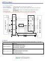
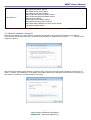
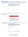
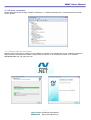
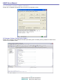
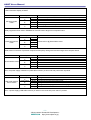
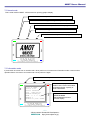
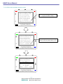
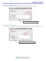
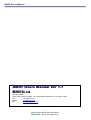
AMOT Users Manual
AMOT Users Manual
Ver 1.7
AMOT
OBJECT
-1- Microcomputer Research & Development OBJECT Co., Ltd. http://www.object.co.jp/
AMOT Users Manual
PanaXSeries and DebugFactory are trademarks of Panasonic Corporation.
WINDOWS are trademarks of Microsoft Corporation.
Adobe Acrobat Reader is a trademark of Adobe Corporation.
The other corporation name, logotype, and product names written in the book are trademarks or registered trademarks of
their corresponding corporations.
Request for your special attention and precautions in using the technical information and
semiconductors described in this book
(1) An export permit needs to be obtained from the competent authorities of the Japanese Government if any of the
products or technologies described in the book and controlled under the “Foreign Exchange and Foreign Trade Law”
is to be exported or taken out of Japan.
(2) The contents of this book are subject to change without notice in matters of improved function.
(3) We are not liable for any damages arising out of the use of the contents of this book, or for any infringement of
patents or other rights owned by a third party.
(4) No part of this book may be reprinted or reproduced by any means without written permission from our company.
(5) OBJECT Co., Ltd. and Panasonic Corporation makes amends for an immediately neither of the use of the customer
of this product and causing or indirect damage.
(6) The wound of this product within 6 months responds from purchase to compensation for damages within the range
where the product purchase price is not exceeded. However, it is assumed the one that the defect liability is not
owed to a similar preceding clause.
(7) We can supply the support for AMOT via E-Mail ([email protected]) and WEB SITE (http://www.object.co.jp) Please
determine the up- to-date information and more on our WEB SITE.
-2- Microcomputer Research & Development OBJECT Co., Ltd. http://www.object.co.jp/
AMOT Users Manual
CONTENTS
[1] PRODUCT OVERVIEW...........................................................................................................................................................................5
1.1 OVERVIEW ................................................................................................................................................................................................5
1.2 SPECIFICATION ........................................................................................................................................................................................5
1.3 PROGRAMMER SPECIFICATION ..............................................................................................................................................................6
1.4 DEBUGGER SPECIFICATION ....................................................................................................................................................................6
[2] PART NAME ..............................................................................................................................................................................................7
[3] PART EXPLANATION ............................................................................................................................................................................8
3.1 USB CONNECTOR ..................................................................................................................................................................................8
3.2 TARGET CONNECTOR (DWIRE8/32A/32L/JTAG)..........................................................................................................................8
3.3 LED ..........................................................................................................................................................................................................8
3.4 DWIRE TARGET POWER SOURCE MONITOR LED.................................................................................................................................9
3.5 LCD AND PUSH-SWITCH (A/B/C) .....................................................................................................................................................9
3.6 DIP-SWITCH ............................................................................................................................................................................................9
3.7 ISOLATION SWITCH .................................................................................................................................................................................10
[4] TARGET CONNECTION ........................................................................................................................................................................11
4.1 DWIRE8/DWIRE32A/DWIRE32L..........................................................................................................................................................11
4.1.1 Target connector table..............................................................................................................................................................11
4.1.2 Connected image chart .............................................................................................................................................................11
4.1.3 Target Circuit Example..............................................................................................................................................................12
4.2 JTAG.......................................................................................................................................................................................................12
4.2.1 Target connector table..............................................................................................................................................................13
4.2.2 Connected image chart .............................................................................................................................................................13
4.2.3 Target Circuit Example..............................................................................................................................................................14
[5] USB DRIVER .............................................................................................................................................................................................14
5.1 USB DRIVER INSTALLATION (WINDOWS7)............................................................................................................................................15
5.2 USB DRIVER UNINSTALLATION ..............................................................................................................................................................17
5.2.1 Microsoft .NET Run time package..........................................................................................................................................17
[6] PROGRAMMER SOFTWARE (AMOBP COMMANDER)...............................................................................................................18
[7] DEBUGGER SOFTWARE (DEBUG FACTORY BUILDER)...........................................................................................................18
[8] OPERATION MODE ................................................................................................................................................................................19
8.1 モード遷移図........................................................................................................................................................................................19
8.2 NORMAL MODE ........................................................................................................................................................................................21
8.3 INFORMATION MODE ................................................................................................................................................................................21
8.4 OFF-LINE PROGRAM MODE ....................................................................................................................................................................22
8.4.1 Off-line mode main menu screen...........................................................................................................................................22
8.4.2 SD card sauce..............................................................................................................................................................................23
8.4.3 Off-line mode sub menu screen.............................................................................................................................................23
8.4.4 Off-line mode command execution screen .........................................................................................................................24
8.5 HAND-HELD MONITOR MODE .................................................................................................................................................................25
8.6 DEMONSTRATION MODE .........................................................................................................................................................................25
[9] HAND-HELD MONITOR ........................................................................................................................................................................26
[10] MICROSD CARD USAGE....................................................................................................................................................................27
10.1 MICROSD SUPPORT INFORMATION .....................................................................................................................................................27
10.2 MICROSD DIRECTION OF CARD INSERTION ........................................................................................................................................27
10.3 USB MASS STORAGE DEVICE ..............................................................................................................................................................27
10.4 OPF FORMAT FILE ...............................................................................................................................................................................28
[11] FIRMWARE UPDATE ............................................................................................................................................................................29
11.1 FIRMWARE UPDATE SEQUENCE ...........................................................................................................................................................29
11.2 FIRMWARE UPDATE SOFTWARE (AMOT_FMUD.EXE).......................................................................................................................29
11.2.1 File selection ..............................................................................................................................................................................29
11.2.2 Program (firmware program)..................................................................................................................................................30
11.2.3 Info (firmware information display) ......................................................................................................................................31
-3- Microcomputer Research & Development OBJECT Co., Ltd. http://www.object.co.jp/
AMOT Users Manual
11.2.4 History (firmware history display)........................................................................................................................................31
-4- Microcomputer Research & Development OBJECT Co., Ltd. http://www.object.co.jp/
AMOT Users Manual
[1] Product Overview
1.1 Overview
AMOT is an on-board development tool for a system microcomputer made of Panasonic. AM (As follows:
microcomputer). AMOT can be used with one as an onboard programmer and an on-board debugger of the
MN101C/MN101E/MN103S/MN103L series. The standard is appended to onboard programmer software (AMOBP
Commander). Please buy DebugFactory Builder for AMOT for the debugger software. Moreover, the software of the
latest version is downloadable from our company WEB site.
1.2 Specification
Product Model
*1
Support microcomputer
Size/Weight
Power Supply
Current
System requirements
Host computer Interface
Support OS
Programmer software
Debugging software
Hand-Held Monitor
Built-in store EEPROM
External flash
Display device
Manual operating device
Information device
Target Interface
Target connection
distance
Target protection
Power supply to target
Support Target voltage
Target power supply
monitor
AMOT MODEL-01D
Panasonic MN101C/MN101E/MN103S/MN103L series
W=69/D=57/H=20(unit:mm) / 80gram
USBBUS POWER only
250mA (MAX500mA/ With automatic return type over current protection)
Temperature when operating (no Dewfall) 0~45℃
Storage temperature (no dewfall) -20~65℃
USB 1.1/2.0(FULL-SPEED) MicroB Standard
Microsoft Windows XP(over SP2)/Vista/7 (32/64bit)
AMOBP Commander / CPU Package over V4.0.0.0
Debug Factory Builder for AMOT
Function that can control target microcomputer and monitor it without connection of
PC *2
4MByte (1to4 Banked)
microSD card (FAT/FAT32 support LFN)
64x128dot monochrome LCD w/t back light
4 RGB LED / One dual-colors LED
3 Push switch (A/B/C)
Buzzer (Operation notification, Error notification, etc.)
DWire8(2wiremodel / 3 wire model)/DWire32A/DWire32L 10Pin (2.7Vto5.0V/
*3
Automatic follow)
JTAG 16Pin (2.7Vto5.0V/ Automatic follow)
Max 1m / Interface clock is 4MHz (Recommendation under 20cm) *4
Isolation, ESD protect, Over current protection, automatic return type over current
protection (500mA)
3.3V / 5.0V (max200mA) *5
2.7Vto 5.0V(Automatic follow) *5
Dual-colors LED (Normality : Green / Error : Red)*6
The upgrade of the firmware is possible by the on-site (special update software
distribution schedule).
AMOT ····················································································1
USB cable (1.5M MicroB) ·····················································1
Product configuration
Target Cable (10P:20cm) ························································1
Software CD-ROM ·································································1
Product warranty card ····························································1
*1 Please confirm a detailed, individual kind on our company WEB site.
*2 when the field is maintained by using LCD, the switch, and LED of AMOT from the user program, it is possible to
use it.
*3 AMOT MODEL-01D doesn't support JTAG.
*4 necessary to lower communication clock (DWire/JTAG) by the circuit and the system requirements of the target
board.
*5 possible only for isolation mode OFF.
*6 Dual-colors LED show the operation of the overvoltage protection. The monitor of the voltage of the target is also
possible at isolation mode OFF.
Version up
-5- Microcomputer Research & Development OBJECT Co., Ltd. http://www.object.co.jp/
AMOT Users Manual
1.3 Programmer Specification
Product Model
Programmer software
Support microcomputer *1
Operational mode
AMOT MODEL-01D
AMOBP Commander over V4.0.0.0 (Free of charge)
CPU package software over V4.0.0.0 (Free of charge)
Panasonic MN101C/MN101E/MN103S/MN103L series
On-line mode / Off-line mode(Built-in EEPROM / microSD card)
Load
Support file format
Panasonic EX, EF, Intel HEX, Motorola S
Panasonic EF, Intel HEX, Motorola S, AMOT OPF format (for microSD
card)
A peculiar security key code to microcomputer is supported. (release/program/status
check)As for the security key code file format, Panasonic PX-FW2 is
interchangeable.
Save
Security key
Sector protect
A peculiar sector protecting to microcomputer is supported. (program/status check)
Program API
Control from other application is possible by the DDE function.
Erase
Program
Verify
Erase
Program
Verify
Erase
Program
Verify
2sec
5sec
1sec (Read verify)
5sec
13sec
2sec (sum verify)
5sec
11sec
2sec (sum verify)
MN101EF32D
(68Kbyte)
E.P.V *2
8sec (Read verify)
MN103SFA7K
(256KByte)
E.P.V
*2
15sec (Read verify)
MN103LF08K
(256KByte)
E.P.V
*2
15sec (Read verify)
MN101EF32D
(68Kbyte)
Off-Line
MN103SFA7K
(256Kbyte)
MN103LF08K
(256KByte)
Program Speed
On-Line
*1 Please confirm a detailed, individual kind on our company WEB site.
*2 E.P.V (Erase + Program + Verify)
1.4 Debugger Specification
Product Model
Debugging software
Support microcomputer *1
Memory mode
Program execute
environment
Step execution
Force break
Break before execute
Software break
Event break
Back trace
H/W trace
Time measure
Real time watch
AMOT MODEL-01D
Debug Factory Builder for AMOT
MN101C/MN101E/MN103S/MN103L series
Single chip / External memory mode
Flash ROM on microcomputer
Assembler code, C source code ( function step execute support)
ESC key
2 points and come break(console position break)
Max 255 points
1 point Data access (data bit mask, Event area)
Call history display
Impropriety
Impropriety
RAM monitor
-6- Microcomputer Research & Development OBJECT Co., Ltd. http://www.object.co.jp/
8sec
20sec
18sec
AMOT Users Manual
Attached to the product (Start.asm) *4
Attached to the product (Start.asm to necessary linked user program code )
OCDDATA, OCDCLK, DMOD, NRST *2 *3
User NMI cannot use it.
The count improvement of the watch dock timer becomes debugger break operation.
Limitations
The undefined instruction execution becomes debugger break operation.
MN101C/E uses the break stack by 13 bytes. *5
*1 Please confirm a detailed, individual kind on our company WEB site.
*2 The PIN name is different according to Microcomputer Please refer to LSI manual of each microcomputer for
details.
*3 AMOT drives the NRST pin with Open Drain. User NRST signal can be connected with a wired OR circuit.
*4 Code size of Start.asm is different according to microcomputer series.
*5 MN103S/MN103L don’t use the user stack.
Start-up code
Debug monitor code
Used microcomputer pin
[2] Part Name
Status LED
SD card access LED
64x128dot LCD
System LED
Target LED
DWire8/32A/32L
Target connector
DWire8/32A/32L
Target connector
JTAG
Target LED
JTAG
Push-Switch C
Push-Switch B
MicroSD card slot
Push-Switch A
USB Connector
Dip-Switch
Target power monitor LED
Extension
Attention! Please do not open the case. The product with signs where the case was opened might not be repaired.
-7- Microcomputer Research & Development OBJECT Co., Ltd. http://www.object.co.jp/
AMOT Users Manual
[3] Part Explanation
3.1 USB Connector
This is MicroB standard USB target connector that connects the personal computer with AMOT. Please do the corner
with the cutting lack on below and insert one with a wide USB connector.
USB cable Plug side
3.2 Target Connector (DWire8/32A/32L/JTAG)
This is a connector connected with the target microcomputer board. 10P at the left of the figure below is for
DWire8/32A/32L. Right side 16P is for JTAG. Please refer to four target connection for details of the signal and the
connection method with the target microcomputer board.
1pin
1pin
3.3 LED
Four LED is arranged in four upper corners of AMOT. The meaning that each LED shows is as shown in the table below.
The lighting color in the figure below is an image.
DWire
STATUS
SYSTEM
JTAG
-8- Microcomputer Research & Development OBJECT Co., Ltd. http://www.object.co.jp/
AMOT Users Manual
LED
BLUE
RED
SYSTEM
Normal
USB Function
GREEN
Firmware
update, and
more
Etc
GREEN blinks at about 2sec BLUE lighting +
intervals usually.
STATUS
SD card access
DWire
DWire access
JTAG
JTAG access
The above-mentioned table midair white column depends on the personal computer side application used.
3.4 DWire Target power source monitor LED
The DWire connector back side of AMOT is equipped with target power source monitor LED. This LED is 2-color
luminescence (GREEN/RED). When the target power supply is not detectable, it is putting out lights. Detection is
GREEN about a normal power supply. Unusual power supply voltage is RED.
3.5 LCD and Push-Switch (A/B/C)
AMOT is 64×128 Graphic LCD dot is installed. It chiefly uses it at the off-line program mode and the hand-held monitor
mode. Please refer [7] Operation Mode for each mode. The figure below is an example in the state that became an
information mode from a normal mode by one time of a short push of "Operation button A".
Push-Switch B
Push-Switch B
Push-Switch B
A M O T Mxxx
Verson x.xx
Serial xxxxxxxx
Date xxxx/xx/xx
EEPROM xxxxKbyte
BANK 0 1 2 3
OPTION
OBJECT Co.,Ltd. JAPAN
Push C
Normal mode LCD Display
3.6 Dip-Switch
Operation button C is selected at a normal mode and the number when short push Off-Line Program is executed once is
selected. An advanced Off-Line program mode is variously installed as for AMOT, and it is also possible to execute an
Off-Line program by the operation the switch once as well as old AM1/3 On-Board Programmer.
ON
↑1
Ex. BANK 2 Select
-9- Microcomputer Research & Development OBJECT Co., Ltd. http://www.object.co.jp/
AMOT Users Manual
Dip-Switch
2
OFF
OFF
ON
ON
1
OFF
ON
OFF
ON
Selected number
BANK 0
BANK 1
BANK 2
BANK 3
3.7 Isolation Switch
This Dip-Switch is a switch that switches the isolation mode in the target interface. Please operate this switch with
tweezers etc. with there must not power supply because it is in the secluded place between target connectors
DWire/JTAG. Isolation mode OFF is used to supply power supply (VDDOUT) from AMOT to the target board and to
operate AMOT only in the power supply from the target board in an off-line mode.
However, we will usually strongly recommend using it in the isolation mode that uses the USB power supply.
NO
1
Target Interface
DWire8/32A/32L
1
OFF
ON
OFF
ON
2
OFF
ON
ON
OFF
3
4
2
3
4
Explanation
Isolation mode ON (Default)
Isolation mode OFF
Set prohibition
OFF
OFF Isolation mode ON (Default)
ON
ON
Isolation mode OFF
JTAG
OFF
ON
Set prohibition
ON
OFF
Attention! 1/2(DWire) 3/4(JTAG) Please set it to ON/OFF by the set.
-10- Microcomputer Research & Development OBJECT Co., Ltd. http://www.object.co.jp/
AMOT Users Manual
[4] Target Connection
4.1 DWire8/DWire32A/DWire32L
It connects it with the DWire connector and the target microcomputer board of AMOT with target cable (10P) of the
product attachment.
9pin
1pin
10pin
2pin
4.1.1 Target connector table
Pin
Signal
1
2
3
NRST
GND
OCDDATA
4
VDD
5
6
7
8
9
10
N.C
N.C
VDDOUT
DMOD
OCDCLK
GND
Direction
Output
I/O
Input
Output
Output
-
Explanation
Microcomputer reset signal l (connects to target microcomputer)
Target GND
Data signal (connects to target microcomputer)
Power supply from target board (2.7Vto5.0V)
Power supply from AMOT (case of not isolation mode)
Please do not connect anything.
Mode signal (connects to target microcomputer)
Clock signal (connects to target microcomputer)
Target GND
4.1.2 Connected image chart
Debugger/Programmer
Target cable
USB cable
64
48
16
32
Target microcomputer board
-11- Microcomputer Research & Development OBJECT Co., Ltd. http://www.object.co.jp/
AMOT Users Manual
4.1.3 Target Circuit Example
・PULL-UP REGISTER .......... Indispensable. 10Kohm to 33Kohm pull-up resister (*1)
・BYPASS CONDENSOR....... Not indispensable. However, mount according to the pattern of the target circuit
though.
・ESD PROTECT ................... Not indispensable. However, use of avalanche type ESD protection diode is
recommended.
・POWER INDUCTOR ........... Not indispensable. However, Use 10uH to 22uH is recommended.
*1 not indispensable when there is a pull-up resistor in the microcomputer such as MN103SFC2D.
PULL- UP REGI STER
1
2
R
RSB5. 6S
DWCL K
DMOD
NC
NC
103( 10K)
9
DWCLK
8
7
DMOD
1
R
2
103( 10K)
RSB5. 6S
6
R
NC
TVDD
DATA
GND
5
1
2
103( 10K)
POWER I NDUCTOR
RSB5. 6S
4
1
2
VDD
10uH
3
DATA
R
2
103( 10K)
1
BYPASS CONDENSOR
0. 1uF
0. 1uF
2
RSB5. 6S
0. 1uF
1
+
NRST
47uF
NRST
GND
4.2 JTAG
It connects it with the DWire connector and the target microcomputer board of AMOT with target cable (16P).
15pin
1pin
2pin
16pin
-12- Microcomputer Research & Development OBJECT Co., Ltd. http://www.object.co.jp/
MN101/ MN103S/ MN103L
10
0. 1uF
DWi r e8/ 32A/ 32L CONNECTOR 10P
ESD PROTECT
AMOT Users Manual
4.2.1 Target connector table
Pin
Signal
Direction
1
XEXRST
Output
2
3
4
5
6
7
8
9
10
11
12
13
14
15
16
VDD
XRESET
EXTRIG
XTRST/TRSSTMOD
GND
TMS
GND
TDO
GND
TDI
GND
GND
TCK
VDD
VDD
Input
Output
Input
Output
Output
Input
Output
Output
Input
Input
Explanation
Low is output synchronizing with the RESET command of the
debugger.
Target I/O power supply (2.7V to 5.0V)
Reset signal of device for debugging (open drain output)
External trigger input for measurement at time (unsupport)
Reset signal for JTAG communication
Target GND
Signal for state machine control of JTAG
Target GND
JTAG data communication
Target GND
JTAG data communication
Target GND
Target GND
JTAG communication clock
Target I/O power supply (2.7V to 5.0V)
Target I/O power supply (2.7V to 5.0V)
4.2.2 Connected image chart
Debugger / Programmer
Target cable
USB cable
64
48
16
32
Target microcomputer board
-13- Microcomputer Research & Development OBJECT Co., Ltd. http://www.object.co.jp/
AMOT Users Manual
4.2.3 Target Circuit Example
・PULL-UP REGISTER .......... Indispensable. 10Kohm to 33Kohm pull-up resister (*1)
・BYPASS CONDENSOR....... Not indispensable. However, mount according to the pattern of the target circuit
though.
・ESD PROTECT ................... Not indispensable. However, use of avalanche type ESD protection diode is
recommended.
・POWER INDUCTOR ........... Not indispensable. However, Use 10uH to 22uH is recommended.
*1 not indispensable when there is a pull-up resistor in the microcomputer such as MN103SFC2D.
ESD PROTECT
EXTRI G
4
PULL- UP REGI STER
1
5
XTRST/ TRSSTMOD
14
TCK
R
RSB5. 6S
103( 10K)
TCK
7
TMS
1
R
2
103( 10K)
RSB5. 6S
R
2
VDD
15
VDD
16
VDD
1
2
VDD
10uH
9
TDO
11
6
8
10
12
13
TDI
1
2
R
RSB5. 6S
103( 10K)
3
1
2
RSB5. 6S
BYPASS CONDENSOR
0. 1uF
NRST
0. 1uF
XRESET
POWER I NDUCTOR
RSB5. 6S
0. 1uF
GND
GND
GND
GND
GND
103( 10K)
+
TDI
2
47uF
TDO
1
0. 1uF
JTAG CONNECTOR 16P
TMS
2
MN101/ MN103S/ MN103L
XEXRST
1
GND
[5] USB driver
The USB driver for AMOT is supplied to attachment CD. Windows demands the driver when AMOT is connected with the
personal computer for the plug and play, and installs it, please specifying "¥USBDriver¥OmWinUsb.inf" in CD-ROM.
Explanation
USB driver support OS
Microsoft Windows XP (over SP2)
Microsoft Windows XP64 (over SP2)
Microsoft Windows Vista 32bit/64bit
Microsoft Windows 7 32bit/64bit
USB driver support product
AMOT
AM1 On-Board Programmer Type1/Type2L *1
AM3 On-Board Programmer Type1/Type2L *1
AM1 Debug Probe DWire *1
AM32L Debug Probe DWire *1
-14- Microcomputer Research & Development OBJECT Co., Ltd. http://www.object.co.jp/
AMOT Users Manual
Old USB driver
*1
AM1 Starter Kit USB I/F DWire8
AM1 Debug Probe Serial USB I/F
AM1 Debug Probe DWire USB I/F
AM3 On-Board Programmer DWire USB I/F
AM1 On-Board Programmer DWire USB I/F
AM3 Starter Kit USB I/F
AM32L Debug Probe DWire USB I/F
AM1 DWire8 Converter Device USB I/F
AM1 UART/USB to DWire8 Converter Device USB I/F
JTAG MINI PROBE USB I/F
*1 please deletes the old USB driver previously when old USB driver (OmUsbi.sys) is installed.
5.1 USB driver installation (Windows7)
Because the message in the figure below is output after it automatic of the USB driver retrieves it when AMOT is
connected with the personal computer in which Microsoft Windows7 is installed for the first time, ・・・・・・ referring to the
computer is clicked.
Next, because the dialog window where the reference place of the driver file is specified is displayed, reference (R), it
clicks on a button, and "USBDriver" of CD-ROM of the product attachment is specified. Please put the check also in (I)
that retrieves * subfolder in this dialog window at that time.
-15- Microcomputer Research & Development OBJECT Co., Ltd. http://www.object.co.jp/
AMOT Users Manual
When (N) after the driver file place is specified to the following is clicked, the driver's installation is begun.
Next, the dialog window where warning of security is shown might be displayed, and, in that case, click (I) that installs
this driver software, please.
The message window that the device driver was correctly installed at the end is displayed, and it is clicked that the name
is "OBJECT WinUSB Device" and click (C) that confirms and shuts, please.
-16- Microcomputer Research & Development OBJECT Co., Ltd. http://www.object.co.jp/
AMOT Users Manual
5.2 USB driver uninstallation
Please delete the device manager "OBJECT USB Device" > “OBJECT WinUsb Device” of Windows about the USB
driver's deletion.
5.2.1 Microsoft .NET Run time package
Microsoft .NET framework is necessary for the USB driver of AMOT. The re-distribution version installer is supplied to
AMOT attachment CD-ROM and installs it, please when the NET such as XP (SP2) framework is not installed.
(¥DotNet¥dotNetFx40_Full_x86_x64.exe)
-17- Microcomputer Research & Development OBJECT Co., Ltd. http://www.object.co.jp/
AMOT Users Manual
[1] Programmer Software (AMOBP Commander)
Please refer to 'AMOBP Commander User’s manual' of the separate volume.
[6] Debugger Software (Debug Factory Builder)
Please refer to 'Debug Factory Builder4 for AMOT quick start guide' and 'Debug Factory Builder4 for AMOT user's
manual' of the separate volume.
-18- Microcomputer Research & Development OBJECT Co., Ltd. http://www.object.co.jp/
AMOT Users Manual
[7] Operation Mode
The operation mode of AMOT has "Normal mode", "Off-line program mode", "Information mode", "Hand-held monitor
mode", and "Demonstration mode". Moreover, there is "USB mass storage device mode" (9.3 Refer to the USB mass
storage device) to use it as microSD card reader. The outline and the operation list of each mode are as shown in the
table below.
7.1 モード遷移図
POWER ON
(USB Plug-in)
Button A keep push
DEMO MODE
Button A short push
Button A short push
Button A short push
Button B short push
NORMAL MODE
(*MSD MODE)
Button A long push
Button B short push
Result displays for
1.5 seconds.
Button B long push
Button A long push
INFORMATION
MODE
OFF-LINE PROGRAM
MODE
ONE-TOUTCH
OFF-LINE PROGRAM
MODE
HAND-HELD MONITOR
MODE
* If a power supply is set to ON, with the button C pushed, it will become USB mass storage device mode (MSD mode).
Each function of an off-line system can also use MSD mode.
Mode
Normal mode
Operation
Push-Switch
Short
A
Long
Push-Switch
Short
B
Long
Short
Push-Switch
C
Long
Explanation
Changes to the information mode.
The reset pulse is output to the target (Low pulse).
Changes to the off-line program mode.
Changes to the hand-held monitor mode.
Off-line program start.
Note:
When starting, mode usually. Graphic opening image of LCD display. The content of BANK specified with the dip switch
in operation button C short push is off-line programmed to the target.
Mode
Information mode
Operation
Push-Switch
Short
A
Long
Push-Switch
Short
B
Long
Short
Push-Switch
C
Long
Explanation
Changes to a normal mode.
-19- Microcomputer Research & Development OBJECT Co., Ltd. http://www.object.co.jp/
AMOT Users Manual
Note:
Inside information display of AMOT
Mode
Off-line program
mode
Operation
Push-Switch
Short
A
Long
Push-Switch
Short
B
Long
Short
Push-Switch
C
Long
Explanation
Source switch (built-in EEPROM/microSD card)
Changes to a normal mode.
Select a bank of built-in EEPROM or select a file of SD card.
Off-line program start / stop.
Note:
Mode programmed from built-in EEPROM or microSD card to target microcomputer board
Mode
Hand-held monitor
mode
Operation
Push-Switch
Short
A
Long
Push-Switch
Short
B
Long
Short
Push-Switch
C
Long
Explanation
Please refer to [9] Hand-held monitor.
Note:
Mode without connection of personal computer that simplicity debugs and monitors target microcomputer board.
Mode
Demonstration mode
Operation
Push-Switch
Short
A
Long
Push-Switch
Short
B
Long
Short
Push-Switch
C
Long
Explanation
Changes to a normal mode.
Buzzer sound ON/OFF switch
Note:
Then, the power supply is started on (USB cable insertion) in this mode with push-switch A pushed.
Mode
USB mass storage
device mode
Operation
Push-Switch
Short
A
Long
Push-Switch
Short
B
Long
Short
Push-Switch
C
Long
Explanation
Changes to the information mode.
The reset pulse is output to the target (Low pulse).
Changes to the off-line program mode.
Changes to the hand-held monitor mode.
changes to off-line program start > off-line program mode.
Note:
Then, a power supply (USB cable insertion) on starts in this mode with push-switch C pushed.
-20- Microcomputer Research & Development OBJECT Co., Ltd. http://www.object.co.jp/
AMOT Users Manual
7.2 Normal mode
This is usual mode of AMOT. LCD becomes an opening graphic display.
Push-Switch A short push:To the information mode
Push-Switch A long push:Target reset pulse output
Push-Switch B short push:To the off-line program mode
Push-Switch B long push:To the hand-held monitor mode
Push-Switch C short push:Off-line program start / stop
7.3 Information mode
If push-switch A is done from a normal mode a short push once, it becomes an information mode. It returns when
operation button A is done to a normal mode a short push once again.
Push-Switch A short push:returns to a normal mode.
A M O T Mxxx
Verson x.xx
Serial xxxxxxxx
Date xxxx/xx/xx
EEPROM xxxxKbyte
BANK 0 1 2 3
SELECT 0
OBJECT Co.,Ltd. JAPAN
Information display
Model name, version information,
and serial number, capacity of
built-in EEPROM
Information with built-in AMOT
EEPROM BANK
Stored BANK becomes a
reverse display.
-21- Microcomputer Research & Development OBJECT Co., Ltd. http://www.object.co.jp/
AMOT Users Manual
7.4 Off-line program mode
It is the mode which runs a program to a target microcomputer board with an AMOT simple substance. Program
sauce serves as EEPROM (1-4 bank) with built-in AMOT, or a microSD card. The change of sauce changes by the
short aggressiveness of manual operation button A. The bank (EEPROM) in sauce or selection of a file (microSD
card) is the short aggressiveness of manual operation button C. Execution of a program goes into a sub menu by the
short aggressiveness of manual operation button C, and chooses four kinds of commands, EPV
(Erase/Program/Verify), Erase, Program, and Verify, by the short aggressiveness of manual operation button B, and it
performs it by the short aggressiveness of manual operation button C. The cancellation under program execution is
also possible at the short aggressiveness of manual operation button C. Moreover, progress information is displayed
on LCD during off-line program execution, and it also displays a result at the time of the end of execution. When a
program is interrupted for manual operation button C, it is displayed on Result as "KEY BREAK". A result is displayed
at the time of the end of an off-line program. It returns to a sub menu by the short aggressiveness of the manual
operation button B or C. If the short aggressiveness of manual operation button C is carried out with a sub menu, it
will return to an off-line mode main menu.
A M O T Mxxx Vxxxx
BANKNo:0
Device:MN101EF32D
F.name:SAMPLE.hex
F.date:2011/03/25
D.sum :0x1234abcd
OPTION:
<SRC> <SEL> <ENT>
7.4.1 Off-line mode main menu screen
Push-switch A short push:returns to a normal mode.
Push-switch A short push: Switch of source
(EEPROM/MicroSD)
Push-switch B short push: File selection
(EEPROM:BANK No / MicroSD:File)
Push-switch C short push :
Program start / stop
Off-line program data information
A M O T Mxxx Vxxxx
BANKNo:0
Device:MN101EF32D
F.name:SAMPLE.hex
F.date:2011/03/25
D.sum :0x1234abcd
OPTION:
<SRC> <SEL> <ENT>
-22- Microcomputer Research & Development OBJECT Co., Ltd. http://www.object.co.jp/
AMOT Users Manual
7.4.2 SD card sauce
OPF file name display when source
is microSD card
A M O T Mxxx Vxxxx
SDFile:hogehoge.opf
Device:N103SFC2D
F.name:Sample.hex
F.date:2011/03/25
D.sum :0x1234abcd
OPTION:
<SRC> <SEL> <ENT>
7.4.3 Off-line mode sub menu screen
A M O T Mxxx Vxxxx
Device:N103SFC2D
F.name:Sample.hex
0: E.P.V.
1: Erase
2: Program
3: Verify
<RET> <SEL> <EXE>
Command execution ( C button )
Command Select (B button)
-23- Microcomputer Research & Development OBJECT Co., Ltd. http://www.object.co.jp/
AMOT Users Manual
7.4.4 Off-line mode command execution screen
A M O T Mxxx Vxxxx
SDFile:hogehoge.opf
Device:N103SFC2D
F.name:Sample.hex
F.date:2011/03/25
D.sum :0x1234abcd
Now on PROGRAM...
Adddress:0x00004000
A M O T Mxxx Vxxxx
SDFile:hogehoge.opf
Device:N103SFC2D
F.name:Sample.hex
F.date:2011/03/25
D.sum :0x1234abcd
Function Complete!
Result = SUCCESS
Under off-line program execution
Progress information display
Off-line program execution result display
Return to sub menu after about 1.5 sec.
A M O T Mxxx Vxxxx
Device:N103SFC2D
F.name:Sample.hex
0:
0: E.P.V.
E.P.V.
1: Erase
2: Program
3: Verify
<RET> <SEL> <EXE>
-24- Microcomputer Research & Development OBJECT Co., Ltd. http://www.object.co.jp/
AMOT Users Manual
7.5 Hand-held monitor mode
Please refer to [8] Hand-held monitor. (P26)
7.6 Demonstration mode
This mode is a demonstration mode displayed repeating information etc. on AMOT. Then, a power supply (USB cable
insertion) on changes to this mode with Push-switch A pushed. It can be a short push of Push-switch B and ON/OFF of
the buzzer sound be a switch in this mode. Moreover, it returns to a normal mode in Push-switch A as it is a long push
and ON-OFF of the power supply doesn't exist.
Returns to a normal mode by Push-switch A
The ON/OFF switch of the buzzer sound is Push-switch B
A M O T M-xxx
Panasonic Advanced
Micro Computer
AM1/AM32S/AM32L
OnBoard Develop Tool
for JTAG/DWire
OBJECT Co.,Ltd. JAPAN
All right reserved
-25- Microcomputer Research & Development OBJECT Co., Ltd. http://www.object.co.jp/
AMOT Users Manual
[8] Hand-held monitor
This function is an off-line, simple monitor mode. The installing function is as shown in the table below. As for each
function, an individually effective/invalid setting is possible. Firmware V1.10 or more and utility software
(AMOT_HHM.exe) of AMOT are necessary to use this hand-held monitor (As follows: HHM). Update firmware and
special utility (AMOT_HHM.exe) can load Dan from our company WEB site. Devices supported as of 2011/08 are only
MN101 series except 2-wire system DWire microcomputer. The release time is undecided though MN103S and the
MN103L series are the support schedules when the future.
Function
Debug Mode
Run/Break
Memory Dump
RAM Change
Watch Memory
Resource Service
Data Logger
Explanation
The target microcomputer is started by debug mode.
Execution and stop of user program
Dump display of user memory (ROM/RAM)
User RAM change
Specified watch display of user memory (ROM/RAM)
LCD, LED, and the switch of AMOT are used as a user program resource.
Logging in the microSD card as for specified data.
Please refer to the AMOT hand-held monitor user's manual for details.
-26- Microcomputer Research & Development OBJECT Co., Ltd. http://www.object.co.jp/
AMOT Users Manual
[9] microSD card usage
This is possible to program it to the target microcomputer board by reading the OPF format file preserved on the
microSD card in the off-line program mode of AMOT. The format of the microSD card supports FAT/FAT32 of the
Windows standard.
Attention! The microSD card is not attached to the product.
9.1 microSD support information
microSD support information
Capacity
256 to 512MByte or 1/2/4/8/16GByte
Speed class
Over Class2
Format
FAT/FAT32 (Windows LFN*1)
*1 not correctly displayed in LCD of AMOT for the file names other than the alphanumeric character eight characters and
four characters (extension “.OPF”).
9.2 microSD Direction of card insertion
The microSD card slot of AMOT is a push in, and a push out. Please do not take out the installed microSD card forcibly
pulling it.
9.3 USB mass storage device
AMOT starts as USB mass storage device (general card reader mode) that the power supply turning on (USB cable
insertion) and is supported by the standard then by Windows with Push-switch C pushed. When the OPF file made with
AMOBP Commander is forwarded to the microSD card, this mode is used. When AMOT starts in this mode, the off-line
mode operation can be used.
Attention! Please note that the microSD card might not be recognized from the operation of an off-line mode of AMOT
when the mount of the USB mass storage device is released from Windows.
The USB cable is inserted with Push-switch C pushed.
Message to show USB
mass storage device
microSD Card Mode
-27- Microcomputer Research & Development OBJECT Co., Ltd. http://www.object.co.jp/
AMOT Users Manual
9.4 OPF Format file
This is a target microcomputer program data file that AMOT uses in the off-line program mode (microSD card source). As
for the OPF format, program data and detailed information on the target microcomputer are stored. The OPF format file is
made by "Save as" command in the Store tab of AMOBP Commander. There is no limitation in the number of OPF files
as long as the capacity of the microSD card permits.
Attention! Please preserve the OPF file in the root directory of the microSD card.
OPF format storage information
Program data
Program data file name
Program data preservation date
Program data Sam
Microcomputer name
Microcomputer interface information
Microcomputer security key information
Microcomputer sector information
Data programmed to microcomputer
Program data file name (not OPF file name).
Program data preservation date
Checksum of program data (32bit length)
Microcomputer name and microcomputer ID, etc.
DWire8 (2-wire system/three line type)/32A/32L/JTAG and communication
clock information, etc.
Security key data and security key program existence, etc.
Programmed sector and protecting program existence, etc.
-28- Microcomputer Research & Development OBJECT Co., Ltd. http://www.object.co.jp/
AMOT Users Manual
[10] Firmware Update
10.1 Firmware Update Sequence
1. AMOT is connected with PC with the USB cable of the product attachment (AMOT should operate correctly as USB
device)
2. AMOT_FMUD.exe is started.
3. Update file (.fmu) is specified clicking "…” button in the right of Update File (*.fmu).
4. "Program" button is clicked, and "It is (Y)" is clicked by the confirmation dialog.
5. The update completion is confirmed.
Attention! The updates time is about 30-60 second.
Attention! Please do not detach power supply (USB) of AMOT, and do not operate the button of AMOT while updating
it.
10.2 Firmware update software (AMOT_FMUD.exe)
This is firmware update software that execute on Windows. The update firmware is binary of the original format
offered by our company file (xxxx.fmu). Please do not connect anything with the target connector of AMOT when you
use this software. Moreover, the installer is not attached, and starts AMOT_FMUD.exe with the directory that
unachieved downloaded AMOT_FMUD_Vxxx.zip, please. The above-mentioned USB driver is installed to use
AMOT_FMUD.exe and it is necessary to recognize AMOT to Windows correctly. Please note that AMOT_FMUD.exe
cannot be used in the USB mass storage device mode.
File selection
Firmware update
start
Firmware
information display
Firmware history
display
Log display window
10.2.1 File selection
The file selection dialog window is displayed, and select pertinent update file (xxxx.fmu), please.
-29- Microcomputer Research & Development OBJECT Co., Ltd. http://www.object.co.jp/
AMOT Users Manual
10.2.2 Program (firmware program)
The content of the firmware update file specified that the Program button is clicked is programmed to AMOT. The
confirmation dialog is displayed, and clicks “Yes”(Y), please. Please do not pull out the USB cable from AMOT, and
touch the operation button of AMOT while programming it.
Attention! SYSTEM LED becomes blinking red if failing in the update of the firmware. The repair is needed and, in that
case, contacts our company, please.
-30- Microcomputer Research & Development OBJECT Co., Ltd. http://www.object.co.jp/
AMOT Users Manual
10.2.3 Info (firmware information display)
The firmware inside information is read when the Info button is clicked and it displays it in the log.
Firmware information display to log
10.2.4 History (firmware history display)
The update history etc. preserved in the firmware is read when the History button is clicked and it displays it in the log.
Firmware history display to log
-31- Microcomputer Research & Development OBJECT Co., Ltd. http://www.object.co.jp/
AMOT Users Manual
AMOT Users Manual Ver 1.7
January 31, 2012
OBJECT Co., Ltd.
560-0032, Japan
Second Floor, Mori New Bldg. 1-3-2 Hotarugaike Higashimachi, Toyonaka, Osaka
TEL
+81 6-6844-1747
E-Mail
[email protected]
URL
http://www.OBJECT.jp/
-32- Microcomputer Research & Development OBJECT Co., Ltd. http://www.object.co.jp/