1
Cat. No. H133-E1-01
E5CN-FR
Limit Controller
USER’S MANUAL
E5CN-FR
Limit Controller
User’s Manual
Produced October 2004
iv
Preface
OMRON products are manufactured for use according to proper procedures by a qualified operator
and only for the purposes described in this manual.
The E5CN-FR is a Limit Controller. The main functions and characteristics of the E5CN-FR Limit Controller are as follows:
• Conforms to FM standards (FM3545/3810).
• In addition to thermocouples and platinum resistance thermometers,
infrared temperature sensors can be selected as the sensor input type.
• Limit outputs can also be cleared using event inputs.
• Communications are supported. (Applicable to E5CN-FR models with
communications.)
• The structure is waterproof (NEMA 4X indoor use, equivalent to IP66).
• Conforms to UL, CSA, and IEC safety standards and EMC Directive.
• The PV display color can be switched to make process status easy to
understand at a glance.
• User calibration of the sensor input is supported.
• A protection function enables restricting the setting data that can be used.
To comply with FM standards (i.e., to restrict careless changes to settings,
such as the limit setting value), set the Operation/Adjustment Protect setting to either 1 or 2 for normal operation. With either of these settings, the
Level/Reset Key can be used only as a Reset Key (to reset the limit output).
This manual describes the operation of the E5CN-FR. Read this manual thoroughly and be sure you
understand it before attempting to use the Limit Controller and use the Limit Controller correctly
according to the information provided. Keep this manual in a safe place for easy reference.
Visual Aids
The following headings appear in the left column of the manual to help you locate different types of
information.
Note Indicates information of particular interest for efficient and convenient operation of the product.
1,2,3...
1. Indicates lists of one sort or another, such as procedures, checklists, etc.
OMRON, 2004
All rights reserved. No part of this publication may be reproduced, stored in a retrieval system, or transmitted, in any form, or
by any means, mechanical, electronic, photocopying, recording, or otherwise, without the prior written permission of
OMRON.
No patent liability is assumed with respect to the use of the information contained herein. Moreover, because OMRON is constantly striving to improve its high-quality products, the information contained in this manual is subject to change without
notice. Every precaution has been taken in the preparation of this manual. Nevertheless, OMRON assumes no responsibility
for errors or omissions. Neither is any liability assumed for damages resulting from the use of the information contained in
this publication.
v
Read and Understand this Manual
Please read and understand this manual before using the product. Please consult your OMRON
representative if you have any questions or comments.
Warranty and Limitations of Liability
WARRANTY
OMRON's exclusive warranty is that the products are free from defects in materials and workmanship for a
period of one year (or other period if specified) from date of sale by OMRON.
OMRON MAKES NO WARRANTY OR REPRESENTATION, EXPRESS OR IMPLIED, REGARDING NONINFRINGEMENT, MERCHANTABILITY, OR FITNESS FOR PARTICULAR PURPOSE OF THE PRODUCTS. ANY
BUYER OR USER ACKNOWLEDGES THAT THE BUYER OR USER ALONE HAS DETERMINED THAT THE
PRODUCTS WILL SUITABLY MEET THE REQUIREMENTS OF THEIR INTENDED USE. OMRON DISCLAIMS ALL
OTHER WARRANTIES, EXPRESS OR IMPLIED.
LIMITATIONS OF LIABILITY
OMRON SHALL NOT BE RESPONSIBLE FOR SPECIAL, INDIRECT, OR CONSEQUENTIAL DAMAGES,
LOSS OF PROFITS OR COMMERCIAL LOSS IN ANY WAY CONNECTED WITH THE PRODUCTS,
WHETHER SUCH CLAIM IS BASED ON CONTRACT, WARRANTY, NEGLIGENCE, OR STRICT
LIABILITY.
In no event shall the responsibility of OMRON for any act exceed the individual price of the product on which
liability is asserted.
IN NO EVENT SHALL OMRON BE RESPONSIBLE FOR WARRANTY, REPAIR, OR OTHER CLAIMS
REGARDING THE PRODUCTS UNLESS OMRON'S ANALYSIS CONFIRMS THAT THE PRODUCTS
WERE PROPERLY HANDLED, STORED, INSTALLED, AND MAINTAINED AND NOT SUBJECT TO
CONTAMINATION, ABUSE, MISUSE, OR INAPPROPRIATE MODIFICATION OR REPAIR.
Application Considerations
SUITABILITY FOR USE
OMRON shall not be responsible for conformity with any standards, codes, or regulations that apply to the
combination of products in the customer's application or use of the products.
At the customer's request, OMRON will provide applicable third party certification documents identifying
ratings and limitations of use that apply to the products. This information by itself is not sufficient for a
complete determination of the suitability of the products in combination with the end product, machine,
system, or other application or use.
The following are some examples of applications for which particular attention must be given. This is not
intended to be an exhaustive list of all possible uses of the products, nor is it intended to imply that the uses
listed may be suitable for the products:
• Outdoor use, uses involving potential chemical contamination or electrical interference, or conditions or
uses not described in this manual.
• Nuclear energy control systems, combustion systems, railroad systems, aviation systems, medical
equipment, amusement machines, vehicles, safety equipment, and installations subject to separate
industry or government regulations.
• Systems, machines, and equipment that could present a risk to life or property.
Please know and observe all prohibitions of use applicable to the products.
NEVER USE THE PRODUCTS FOR AN APPLICATION INVOLVING SERIOUS RISK TO LIFE OR
PROPERTY WITHOUT ENSURING THAT THE SYSTEM AS A WHOLE HAS BEEN DESIGNED TO
ADDRESS THE RISKS, AND THAT THE OMRON PRODUCTS ARE PROPERLY RATED AND INSTALLED
FOR THE INTENDED USE WITHIN THE OVERALL EQUIPMENT OR SYSTEM.
vi
PROGRAMMABLE PRODUCTS
OMRON shall not be responsible for the user's programming of a programmable product, or any
consequence thereof.
Disclaimers
CHANGE IN SPECIFICATIONS
Product specifications and accessories may be changed at any time based on improvements and other
reasons.
It is our practice to change model numbers when published ratings or features are changed, or when
significant construction changes are made. However, some specifications of the products may be changed
without any notice. When in doubt, special model numbers may be assigned to fix or establish key
specifications for your application on your request. Please consult with your OMRON representative at any
time to confirm actual specifications of purchased products.
DIMENSIONS AND WEIGHTS
Dimensions and weights are nominal and are not to be used for manufacturing purposes, even when
tolerances are shown.
PERFORMANCE DATA
Performance data given in this manual is provided as a guide for the user in determining suitability and does
not constitute a warranty. It may represent the result of OMRON's test conditions, and the users must
correlate it to actual application requirements. Actual performance is subject to the OMRON Warranty and
Limitations of Liability.
ERRORS AND OMISSIONS
The information in this document has been carefully checked and is believed to be accurate; however, no
responsibility is assumed for clerical, typographical, or proofreading errors, or omissions.
vii
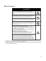
Safety Precautions
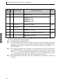
■ Definition of Precautionary Information
This manual uses the following notation to indicate precautions required to
safely operate the E5CN-FR.
The safety precautions that are provided are extremely important to safety.
Always read and heed the information provided in all safety precautions.
The following notation is used.
CAUTION
Indicates a potentially hazardous situation which, if not
avoided, is likely to result in minor or moderate injury or in
property damage.
■ Symbols
Symbol
Meaning
General Caution
Indicates non-specific general cautions, warnings, and
dangers.
Caution
Electrical Shock Caution
Indicates possibility of electric shock under specific
conditions.
General Prohibition
Indicates non-specific general prohibitions.
Prohibition
Mandatory
Caution
viii
Disassembly Prohibition
Indicates prohibitions when there is a possibility of
injury, such as from electric shock, as the result of
disassembly.
General Caution
Indicates non-specific general cautions, warnings, and
dangers.
■ Safety Precautions
CAUTION
Do not touch the terminals while power is being supplied.
Doing so may occasionally result in minor injury due to electric
shock.
Do not allow pieces of metal, wire clippings, or fine metallic shavings or filings from installation to enter the product. Doing so may
occasionally result in electric shock, fire, or malfunction.
Do not use the product where subject to flammable or explosive
gas. Otherwise, minor injury from explosion may occasionally
occur.
Never disassemble, modify, or repair the product or touch any of
the internal parts. Minor electric shock, fire, or malfunction may
occasionally occur.
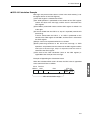
CAUTION - Risk of Fire and Electric Shock
a) This product is UL listed as Open Type Process Control
Equipment. It must be mounted in an enclosure that does not
allow fire to escape externally.
b) More than one disconnect switch may be required to de-energize the equipment before servicing.
c) Signal inputs are SELV, limited energy.*1
d) Caution: To reduce the risk of fire or electric shock, do not
interconnect the outputs of different Class 2 circuits.*2
If the output relays are used past their rated load or life
expectancy, contact fusing or burning may occasionally
occur. Always consider the application conditions and the inrush
current, and use the output relays within their rated load and
electrical life expectancy. The life expectancy of output relays
varies considerably with the output load and switching conditions.
*1
*2
An SELV circuit is one separated from the power supply with double insulation or reinforced insulation,
that does not exceed 30 V r.m.s. and 42.4 V peak or 60 VDC.
A class 2 power supply is one tested and certified by UL as have the current and voltage of the secondary
output restricted to specific levels.
ix
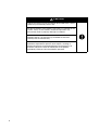
CAUTION
Tighten the terminal screws to between 0.74 and 0.9 N.m. Loose
screws may occasionally result in fire.
Set the parameters of the product so that they are suitable for the
system. If they are not suitable, unexpected operation may
occasionally result in property damage or accidents.
WARNING: To reduce the risk of electric shock or fire, install in a
Pollution Degree 2 environment (a controlled environment
relatively free of contaminants).
A malfunction in the product may occasionally make control
operations impossible or prevent alarm outputs, resulting in
property damage to connected equipment and machinery. To
maintain safety in the event of malfunction of the product,
periodically check the Limit ControllerÅfs operation.
x
Precautions for Safe Use
1)
2)
3)
4)
5)
6)
7)
8)
9)
10)
11)
12)
13)
14)
15)
Do not use this product in the following places:
• Places directly subject to heat radiated from heating equipment.
• Places subject to splashing liquid or oil atmosphere.
• Places subject to direct sunlight.
• Places subject to dust or corrosive gas (in particular, sulfide gas and ammonia gas).
• Places subject to intense temperature change.
• Places subject to icing and condensation.
• Places subject to vibration and large shocks.
Use and store the Limit Controller within the rated ambient temperature and humidity.
When two or more Limit Controllers or Temperature Controllers are mounted close together horizontally or
vertically, the heat generated by the Controllers will cause the Limit Controller's internal temperature to
rise and shorten the Controller's service life. In such a case, use forced cooling by fans or other means of
air ventilation to cool down the Limit Controllers.
To allow heat to escape, do not block the area around the product.
Do not block the ventilation holes on the product.
Be sure to wire properly with correct polarity of terminals.
Use specified size (M3.5, width 7.2 mm or less) crimped terminals for wiring. Use wires with a gage of
AWG24 to AWG14 (equal to cross-sectional areas of 0.205 to 2.081 mm2). (The stripping length is 5 to
6 mm.)
Do not wire the terminals that are not used.
To avoid inductive noise, keep the wiring for the Limit Controller's terminal block away from power cables
carrying high voltages or large currents. Also, do not wire power lines together with or parallel to Limit
Controller wiring. Using shielded cables and using separate conduits or ducts is recommended.
When a noise filter is used at the power supply, first check the voltage or current, and attach the noise
filter as close as possible to the Limit Controller.
Allow as much space as possible between the Limit Controller and devices that generate powerful high
frequencies (high-frequency welders, high-frequency sewing machines, etc.) or surge.
Use this product within the rated load and power supply.
Make sure that the rated voltage is attained within two seconds of turning the power ON.
Make sure the product has 30 minutes or more for warm up.
A switch or circuit breaker must be provided close to this product. The switch or circuit breaker must be
within easy reach of the operator, and must be marked as a disconnecting means for this unit.
Always turn OFF the power supply before pulling out the interior of the product, and never touch nor apply
shock to the terminals or electronic components. When inserting the interior of the product, do not allow
the electronic components to touch the case.
Do not use paint thinner or similar chemical to clean with. Use standard grade alcohol.
Design the system (e.g., control panel) considering the 2 second of delay that the product’s output to be
set after power ON.
The output may turn OFF when shifting to certain levels. Take this into consideration when performing
control.
xi
● Service Life
Use the Limit Controller within the following temperature and humidity ranges:
Temperature: −10 to 55°C (with no icing or condensation), Humidity: 25% to 85%
If the Limit Controller is installed inside a control board, the ambient temperature must be kept under
55°C, including the temperature around the Controller.
The service life of electronic devices like Limit Controllers is determined not only by the number of
times the relay is switched but also by the service life of internal electronic components. Component
service life is affected by the ambient temperature: the higher the temperature, the shorter the service
life and, the lower the temperature, the longer the service life. Therefore, the service life can be
extended by lowering the temperature of the Limit Controller.
When two or more Limit Controllers or Temperature Controllers are mounted close together horizontally or vertically, the heat generated by the Controllers will cause the Limit Controller's internal temperature to rise and shorten the Controller's service life. In such a case, use forced cooling by fans or
other means of air ventilation to cool down the Limit Controllers. When providing forced cooling, however, be careful not to cool down the terminals sections alone to avoid measurement errors.
● Ambient Noise
To avoid inductive noise, keep the wiring for the Limit Controller's terminal block wiring away from
power cables carrying high voltages or large currents. Also, do not wire power lines together with or
parallel to Limit Controller wiring. Using shielded cables and using separate conduits or ducts is recommended.
Attach a surge suppressor or noise filter to peripheral devices that generate noise (in particular,
motors, transformers, solenoids, magnetic coils or other equipment that have an inductance component). When a noise filter is used at the power supply, first check the voltage or current, and attach the
noise filter as close as possible to the Limit Controller.
Allow as much space as possible between the Limit Controller and devices that generate powerful high
frequencies (high-frequency welders, high-frequency sewing machines, etc.) or surge.
● Ensuring Measurement Accuracy
When extending or connecting the thermocouple lead wire, be sure to use compensating wires that
match the thermocouple types.
When extending or connecting the lead wire of the platinum resistance thermometer, be sure to use
wires that have low resistance and keep the resistance of the three lead wires the same.
Mount the Limit Controller so that it is horizontally level.
If the measurement accuracy is low, check to see if input shift has been set correctly.
● Waterproofing
The degree of protection is as shown below. Sections without any specification on their degree of protection or those with IP@0 are not waterproof.
Front panel: NEMA4X for indoor use (equivalent to IP66)
Rear case: IP20, Terminal section: IP00
xii
Precautions for Correct Use
1)
2)
3)
It takes approximately two seconds for the outputs to turn ON from after the power supply is turned ON.
This two-second delay must be considered when incorporating Limit Controllers in a sequence circuit.
Allow at least 30 minutes for warming up.
Avoid using the Controller in places near a radio, television set, or wireless installing. The Controller may
cause radio disturbance for these devices.
xiii
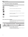
Conventions Used in This Manual
Meanings of Abbreviations
The following abbreviations are used in parameter names, figures and in text explanations. These
abbreviations mean the following:
PV
Symbol
Term
Process value
SP
SV
Limit setting value
Set value
EU
Engineering unit (See note.)
Note “EU” stands for Engineering Unit. EU is used as the minimum unit for engineering units such as °C, m,
and g. The size of EU varies according to the input type.
For example, when the input temperature setting range is –200 to +1300°C, 1 EU is 1°C, and when the
input temperature setting range is –20.0 to +500.0°C, 1 EU is 0.1°C.
For analog inputs, the size of EU varies according to the decimal point position of the scaling setting,
and 1 EU becomes the minimum scaling unit.
xiv
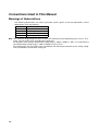
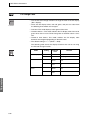
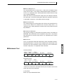
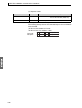
How to Read Display Symbols
The following tables show the correspondence between the symbols displayed on the displays and
alphabet characters. The default is for 11-segment displays.
a b c d e f g h i j k l m
A B C D E F G H I
J K L M
n o p q r s t u v w x y z
N O P Q R S T U V W X Y Z
xv
xvi
TABLE OF CONTENTS
Preface . . . . . . . . . . . . . . . . . . . . . . . . . . . . . . . . . . . . . . . . . . . . . . .
Visual Aids . . . . . . . . . . . . . . . . . . . . . . . . . . . . . . . . . . . . . . . . . . . .
Read and Understand this Manual . . . . . . . . . . . . . . . . . . . . . . . . . .
Safety Precautions . . . . . . . . . . . . . . . . . . . . . . . . . . . . . . . . . . . . . .
Precautions for Safe Use . . . . . . . . . . . . . . . . . . . . . . . . . . . . . . . . . .
Precautions for Correct Use . . . . . . . . . . . . . . . . . . . . . . . . . . . . . . .
Conventions Used in This Manual . . . . . . . . . . . . . . . . . . . . . . . . . .
How to Read Display Symbols . . . . . . . . . . . . . . . . . . . . . . . . . . . . .
v
v
vi
viii
xi
xiii
xiv
xv
PART 1: Main Functions
SECTION 1
Introduction
This section introduces the components, features, and main functions of the E5CN-FR Limit Controller.
Read this section carefully before using the Limit Controller for the first time.
1.1
1.2
1.3
1.4
Names of Parts . . . . . . . . . . . . . . . . . . . . . . . . . . . . . . . . . . . . . . . . . . . . . . . . . . . . . . . . . . . .
1-2
Front Panel . . . . . . . . . . . . . . . . . . . . . . . . . . . . . . . . . . . . . . . . . . . . . . . . . . . . . . . . . . .
1-2
Meanings of Indicators . . . . . . . . . . . . . . . . . . . . . . . . . . . . . . . . . . . . . . . . . . . . . . . . . .
1-2
Using the Keys . . . . . . . . . . . . . . . . . . . . . . . . . . . . . . . . . . . . . . . . . . . . . . . . . . . . . . . .
1-3
I/O Configuration and Main Functions . . . . . . . . . . . . . . . . . . . . . . . . . . . . . . . . . . . . . . . . .
1-4
I/O Configuration . . . . . . . . . . . . . . . . . . . . . . . . . . . . . . . . . . . . . . . . . . . . . . . . . . . . . .
1-4
Main Functions. . . . . . . . . . . . . . . . . . . . . . . . . . . . . . . . . . . . . . . . . . . . . . . . . . . . . . . .
1-5
Setting Level Configuration and Key Operations . . . . . . . . . . . . . . . . . . . . . . . . . . . . . . . . .
1-7
Selecting Parameters . . . . . . . . . . . . . . . . . . . . . . . . . . . . . . . . . . . . . . . . . . . . . . . . . . .
1-9
Fixing Settings . . . . . . . . . . . . . . . . . . . . . . . . . . . . . . . . . . . . . . . . . . . . . . . . . . . . . . . .
1-9
Communications Function. . . . . . . . . . . . . . . . . . . . . . . . . . . . . . . . . . . . . . . . . . . . . . . . . . .
1-10
SECTION 2
Preparations
This section describes the steps required before turning ON the power, including settings, installation,
and wiring.
2.1
2.2
Installation . . . . . . . . . . . . . . . . . . . . . . . . . . . . . . . . . . . . . . . . . . . . . . . . . . . . . . . . . . . . . . .
2-2
Dimensions . . . . . . . . . . . . . . . . . . . . . . . . . . . . . . . . . . . . . . . . . . . . . . . . . . . . . . . . . . .
2-2
Panel Cutout . . . . . . . . . . . . . . . . . . . . . . . . . . . . . . . . . . . . . . . . . . . . . . . . . . . . . . . . . .
2-2
Mounting . . . . . . . . . . . . . . . . . . . . . . . . . . . . . . . . . . . . . . . . . . . . . . . . . . . . . . . . . . . .
2-3
Removing the E5CN-FR from the Case . . . . . . . . . . . . . . . . . . . . . . . . . . . . . . . . . . . . .
2-4
Wiring Terminals . . . . . . . . . . . . . . . . . . . . . . . . . . . . . . . . . . . . . . . . . . . . . . . . . . . . . . . . . .
2-5
Terminal Arrangement . . . . . . . . . . . . . . . . . . . . . . . . . . . . . . . . . . . . . . . . . . . . . . . . . .
2-5
Precautions when Wiring . . . . . . . . . . . . . . . . . . . . . . . . . . . . . . . . . . . . . . . . . . . . . . . .
2-5
Wiring . . . . . . . . . . . . . . . . . . . . . . . . . . . . . . . . . . . . . . . . . . . . . . . . . . . . . . . . . . . . . . .
2-6
xvii
TABLE OF CONTENTS
SECTION 3
Basic Operation
This section provides specific examples to explain the basic operation of the E5CN-FR Limit Controller.
3.1
Initial Setting Examples. . . . . . . . . . . . . . . . . . . . . . . . . . . . . . . . . . . . . . . . . . . . . . . . . . . . .
3-2
3.2
Setting the Input Type . . . . . . . . . . . . . . . . . . . . . . . . . . . . . . . . . . . . . . . . . . . . . . . . . . . . . .
3-3
Input Type. . . . . . . . . . . . . . . . . . . . . . . . . . . . . . . . . . . . . . . . . . . . . . . . . . . . . . . . . . . .
3-3
3.3
Selecting the Temperature Unit . . . . . . . . . . . . . . . . . . . . . . . . . . . . . . . . . . . . . . . . . . . . . . .
3-5
Temperature Unit . . . . . . . . . . . . . . . . . . . . . . . . . . . . . . . . . . . . . . . . . . . . . . . . . . . . . .
3-5
Using the Limit Controller Function . . . . . . . . . . . . . . . . . . . . . . . . . . . . . . . . . . . . . . . . . . .
3-6
Selecting Upper/Lower Limit. . . . . . . . . . . . . . . . . . . . . . . . . . . . . . . . . . . . . . . . . . . . .
3-6
Changing the Limit Setting Value . . . . . . . . . . . . . . . . . . . . . . . . . . . . . . . . . . . . . . . . .
3-7
Resetting the Limit Output . . . . . . . . . . . . . . . . . . . . . . . . . . . . . . . . . . . . . . . . . . . . . . .
3-8
Alarm Outputs . . . . . . . . . . . . . . . . . . . . . . . . . . . . . . . . . . . . . . . . . . . . . . . . . . . . . . . . . . . .
3-9
Alarm Types . . . . . . . . . . . . . . . . . . . . . . . . . . . . . . . . . . . . . . . . . . . . . . . . . . . . . . . . . .
3-9
Alarm Values . . . . . . . . . . . . . . . . . . . . . . . . . . . . . . . . . . . . . . . . . . . . . . . . . . . . . . . . .
3-10
Annunciator . . . . . . . . . . . . . . . . . . . . . . . . . . . . . . . . . . . . . . . . . . . . . . . . . . . . . . . . . .
3-12
3.4
3.5
SECTION 4
Applications Operations
This section describes each function in detail to help make the most of the E5CN-FR Limit Controller's
functionality and capabilities.
4.1
4.2
4-2
Shifting Inputs . . . . . . . . . . . . . . . . . . . . . . . . . . . . . . . . . . . . . . . . . . . . . . . . . . . . . . . .
4-2
How to Calculate Input Shift Values for a 2-point Shift. . . . . . . . . . . . . . . . . . . . . . . . .
4-4
Alarm Hysteresis . . . . . . . . . . . . . . . . . . . . . . . . . . . . . . . . . . . . . . . . . . . . . . . . . . . . . . . . . .
4-7
Standby Sequence. . . . . . . . . . . . . . . . . . . . . . . . . . . . . . . . . . . . . . . . . . . . . . . . . . . . . .
4-7
Alarm Latch . . . . . . . . . . . . . . . . . . . . . . . . . . . . . . . . . . . . . . . . . . . . . . . . . . . . . . . . . .
4-7
Close in Alarm/Open in Alarm. . . . . . . . . . . . . . . . . . . . . . . . . . . . . . . . . . . . . . . . . . . .
4-8
Using Event Inputs . . . . . . . . . . . . . . . . . . . . . . . . . . . . . . . . . . . . . . . . . . . . . . . . . . . . . . . .
4-10
Event Input Functions. . . . . . . . . . . . . . . . . . . . . . . . . . . . . . . . . . . . . . . . . . . . . . . . . . .
4-10
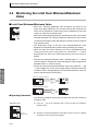
Monitoring the Limit Over Continuation Time . . . . . . . . . . . . . . . . . . . . . . . . . . . . . . . . . . .
4-12
Limit Over Continuation Time . . . . . . . . . . . . . . . . . . . . . . . . . . . . . . . . . . . . . . . . . . . .
4-12
Monitoring the Limit Over Minimum/Maximum Value . . . . . . . . . . . . . . . . . . . . . . . . . . . .
4-14
Limit Over Minimum/Maximum Value . . . . . . . . . . . . . . . . . . . . . . . . . . . . . . . . . . . . .
4-14
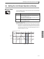
Setting the Limit Output Operation at Startup. . . . . . . . . . . . . . . . . . . . . . . . . . . . . . . . . . . .
4-15
Restart Mode . . . . . . . . . . . . . . . . . . . . . . . . . . . . . . . . . . . . . . . . . . . . . . . . . . . . . . . . .
4-15
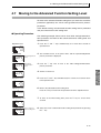
4.7
Moving to the Advanced Function Setting Level . . . . . . . . . . . . . . . . . . . . . . . . . . . . . . . . .
4-17
4.8
Using the Key Protect Level . . . . . . . . . . . . . . . . . . . . . . . . . . . . . . . . . . . . . . . . . . . . . . . . .
4-19
Protection . . . . . . . . . . . . . . . . . . . . . . . . . . . . . . . . . . . . . . . . . . . . . . . . . . . . . . . . . . . .
4-19
Entering the Password to Move to the Protect Level . . . . . . . . . . . . . . . . . . . . . . . . . . .
4-20
Communications Operation Command to Move to the Protect Level . . . . . . . . . . . . . .
4-22
4.3
4.4
4.5
4.6
xviii
Shifting Input Values . . . . . . . . . . . . . . . . . . . . . . . . . . . . . . . . . . . . . . . . . . . . . . . . . . . . . . .
TABLE OF CONTENTS
4.9
PV Change Color. . . . . . . . . . . . . . . . . . . . . . . . . . . . . . . . . . . . . . . . . . . . . . . . . . . . . . . . . .
4-23
PV Color Change Function . . . . . . . . . . . . . . . . . . . . . . . . . . . . . . . . . . . . . . . . . . . . . .
4-23
Setting. . . . . . . . . . . . . . . . . . . . . . . . . . . . . . . . . . . . . . . . . . . . . . . . . . . . . . . . . . . . . . .
4-23
SECTION 5
Parameters
This section describes the E5CN-FR Limit Controller's parameter settings. Use this section as a reference.
5.1
Conventions Used in this Section . . . . . . . . . . . . . . . . . . . . . . . . . . . . . . . . . . . . . . . . . . . . .
5-2
5.2
Protect Level . . . . . . . . . . . . . . . . . . . . . . . . . . . . . . . . . . . . . . . . . . . . . . . . . . . . . . . . . . . . .
5-3
5.3
Operation Level . . . . . . . . . . . . . . . . . . . . . . . . . . . . . . . . . . . . . . . . . . . . . . . . . . . . . . . . . . .
5-6
5.4
Adjustment Level. . . . . . . . . . . . . . . . . . . . . . . . . . . . . . . . . . . . . . . . . . . . . . . . . . . . . . . . . .
5-9
5.5
Initial Setting Level . . . . . . . . . . . . . . . . . . . . . . . . . . . . . . . . . . . . . . . . . . . . . . . . . . . . . . . .
5-15
5.6
Advanced Function Setting Level . . . . . . . . . . . . . . . . . . . . . . . . . . . . . . . . . . . . . . . . . . . . .
5-21
5.7
Communications Setting Level . . . . . . . . . . . . . . . . . . . . . . . . . . . . . . . . . . . . . . . . . . . . . . .
5-31
SECTION 6
CALIBRATION
This section explains how to calibrate the Limit Controller.
6.1
Parameter Structure . . . . . . . . . . . . . . . . . . . . . . . . . . . . . . . . . . . . . . . . . . . . . . . . . . . . . . . .
6-2
6.2
User Calibration. . . . . . . . . . . . . . . . . . . . . . . . . . . . . . . . . . . . . . . . . . . . . . . . . . . . . . . . . . .
6-4
6.3
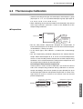
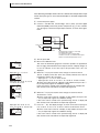
Thermocouple Calibration . . . . . . . . . . . . . . . . . . . . . . . . . . . . . . . . . . . . . . . . . . . . . . . . . . .
6-5
6.4
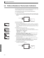
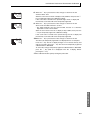
Platinum Resistance Thermometer Calibration . . . . . . . . . . . . . . . . . . . . . . . . . . . . . . . . . . .
6-8
6.5
Checking Indication Accuracy . . . . . . . . . . . . . . . . . . . . . . . . . . . . . . . . . . . . . . . . . . . . . . .
6-10
Appendix
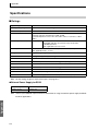
Specifications. . . . . . . . . . . . . . . . . . . . . . . . . . . . . . . . . . . . . . . . . . . . . . . . . . . . . . . . . . . . . . . . . .
A-2
Ratings . . . . . . . . . . . . . . . . . . . . . . . . . . . . . . . . . . . . . . . . . . . . . . . . . . . . . . . . . . . . . .
A-2
Characteristics . . . . . . . . . . . . . . . . . . . . . . . . . . . . . . . . . . . . . . . . . . . . . . . . . . . . . . . .
A-3
Error Displays . . . . . . . . . . . . . . . . . . . . . . . . . . . . . . . . . . . . . . . . . . . . . . . . . . . . . . . . . . . . . . . . .
A-4
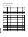
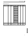
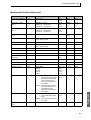
Parameter Operation Lists . . . . . . . . . . . . . . . . . . . . . . . . . . . . . . . . . . . . . . . . . . . . . . . . . . . . . . . .
A-6
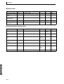
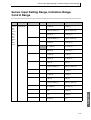
Sensor Input Setting Range, Indication Range, Control Range. . . . . . . . . . . . . . . . . . . . . . . . . . . .
A-11
Setting Levels Diagram . . . . . . . . . . . . . . . . . . . . . . . . . . . . . . . . . . . . . . . . . . . . . . . . . . . . . . . . . .
A-13
Parameter Flow . . . . . . . . . . . . . . . . . . . . . . . . . . . . . . . . . . . . . . . . . . . . . . . . . . . . . . . . . . . . . . . .
A-14
xix
TABLE OF CONTENTS
PART 2: Communications
SECTION 1
Communications Methods
This section introduces the supported communications methods and device wiring methods. Read and
understand this section first in order to wire the devices correctly.
1.1
Overview of Communications Methods . . . . . . . . . . . . . . . . . . . . . . . . . . . . . . . . . . . . . . . .
1-2
Introduction . . . . . . . . . . . . . . . . . . . . . . . . . . . . . . . . . . . . . . . . . . . . . . . . . . . . . . . . . .
1-2
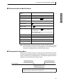
Communications Specifications . . . . . . . . . . . . . . . . . . . . . . . . . . . . . . . . . . . . . . . . . . .
1-3
Transmission Procedure . . . . . . . . . . . . . . . . . . . . . . . . . . . . . . . . . . . . . . . . . . . . . . . . .
1-3
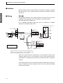
Interface . . . . . . . . . . . . . . . . . . . . . . . . . . . . . . . . . . . . . . . . . . . . . . . . . . . . . . . . . . . . .
1-4
Wiring . . . . . . . . . . . . . . . . . . . . . . . . . . . . . . . . . . . . . . . . . . . . . . . . . . . . . . . . . . . . . . .
1-4
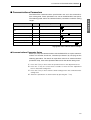
Communications Parameters . . . . . . . . . . . . . . . . . . . . . . . . . . . . . . . . . . . . . . . . . . . . .
1-5
SECTION 2
CompoWay/F Communications Procedures
Read this section when using CompoWay/F communications to perform operations from a host computer, such as reading/writing variable area data or sending operation commands.
2.1
2.2
2.3
2.4
xx
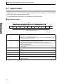
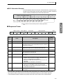
Data Format . . . . . . . . . . . . . . . . . . . . . . . . . . . . . . . . . . . . . . . . . . . . . . . . . . . . . . . . . . . . . .
2-2
Command Frame . . . . . . . . . . . . . . . . . . . . . . . . . . . . . . . . . . . . . . . . . . . . . . . . . . . . . .
2-2
Response Frame . . . . . . . . . . . . . . . . . . . . . . . . . . . . . . . . . . . . . . . . . . . . . . . . . . . . . . .
2-3
Communications Data . . . . . . . . . . . . . . . . . . . . . . . . . . . . . . . . . . . . . . . . . . . . . . . . . .
2-4
End Code Example . . . . . . . . . . . . . . . . . . . . . . . . . . . . . . . . . . . . . . . . . . . . . . . . . . . . .
2-4
Structure of Command Text. . . . . . . . . . . . . . . . . . . . . . . . . . . . . . . . . . . . . . . . . . . . . . . . . .
2-6
PDU Structure . . . . . . . . . . . . . . . . . . . . . . . . . . . . . . . . . . . . . . . . . . . . . . . . . . . . . . . .
2-6
Area Definitions . . . . . . . . . . . . . . . . . . . . . . . . . . . . . . . . . . . . . . . . . . . . . . . . . . . . . . .
2-6
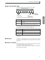
Type Code (Variable Type). . . . . . . . . . . . . . . . . . . . . . . . . . . . . . . . . . . . . . . . . . . . . . .
2-7
Addresses . . . . . . . . . . . . . . . . . . . . . . . . . . . . . . . . . . . . . . . . . . . . . . . . . . . . . . . . . . . .
2-7
Number of Elements. . . . . . . . . . . . . . . . . . . . . . . . . . . . . . . . . . . . . . . . . . . . . . . . . . . .
2-7
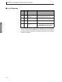
List of Services . . . . . . . . . . . . . . . . . . . . . . . . . . . . . . . . . . . . . . . . . . . . . . . . . . . . . . . .
2-8
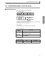
Detailed Description of the Services . . . . . . . . . . . . . . . . . . . . . . . . . . . . . . . . . . . . . . . . . . .
2-9
Read Variable Area. . . . . . . . . . . . . . . . . . . . . . . . . . . . . . . . . . . . . . . . . . . . . . . . . . . . .
2-9
Write Variable Area . . . . . . . . . . . . . . . . . . . . . . . . . . . . . . . . . . . . . . . . . . . . . . . . . . . .
2-10
Read Controller Attributes . . . . . . . . . . . . . . . . . . . . . . . . . . . . . . . . . . . . . . . . . . . . . . .
2-12
Read Controller Status . . . . . . . . . . . . . . . . . . . . . . . . . . . . . . . . . . . . . . . . . . . . . . . . . .
2-13
Echoback Test. . . . . . . . . . . . . . . . . . . . . . . . . . . . . . . . . . . . . . . . . . . . . . . . . . . . . . . . .
2-14
Operation Command . . . . . . . . . . . . . . . . . . . . . . . . . . . . . . . . . . . . . . . . . . . . . . . . . . .
2-15
Response Code List . . . . . . . . . . . . . . . . . . . . . . . . . . . . . . . . . . . . . . . . . . . . . . . . . . . . . . . .
2-18
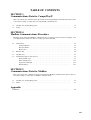
TABLE OF CONTENTS
SECTION 3
Communications Data for CompoWay/F
This section shows the communications data format used in CompoWay/F communications. Refer to this
section when reading or setting data via CompoWay/F communications.
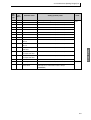
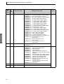
3.1
Variable Area (Setting Range) List . . . . . . . . . . . . . . . . . . . . . . . . . . . . . . . . . . . . . . . . . . . .
3-2
3.2
Status . . . . . . . . . . . . . . . . . . . . . . . . . . . . . . . . . . . . . . . . . . . . . . . . . . . . . . . . . . . . . . . . . . .
3-7
SECTION 4
Modbus Communications Procedure
Read this section when using Modbus communications to perform operations from a host computer, such
as reading/writing variable area data or sending operation commands.
4.1
Data Format . . . . . . . . . . . . . . . . . . . . . . . . . . . . . . . . . . . . . . . . . . . . . . . . . . . . . . . . . . . . . .
4-2
Command Frame . . . . . . . . . . . . . . . . . . . . . . . . . . . . . . . . . . . . . . . . . . . . . . . . . . . . . .
4-2
Response Frame . . . . . . . . . . . . . . . . . . . . . . . . . . . . . . . . . . . . . . . . . . . . . . . . . . . . . . .
4-4
Error Codes. . . . . . . . . . . . . . . . . . . . . . . . . . . . . . . . . . . . . . . . . . . . . . . . . . . . . . . . . . .
4-5
4.2
Function List . . . . . . . . . . . . . . . . . . . . . . . . . . . . . . . . . . . . . . . . . . . . . . . . . . . . . . . . . . . . .
4-6
4.3
Variable Area . . . . . . . . . . . . . . . . . . . . . . . . . . . . . . . . . . . . . . . . . . . . . . . . . . . . . . . . . . . . .
4-7
4.4
Detailed Description of the Services . . . . . . . . . . . . . . . . . . . . . . . . . . . . . . . . . . . . . . . . . . .
4-9
Read Variable Area. . . . . . . . . . . . . . . . . . . . . . . . . . . . . . . . . . . . . . . . . . . . . . . . . . . . .
4-9
Write Variable Area . . . . . . . . . . . . . . . . . . . . . . . . . . . . . . . . . . . . . . . . . . . . . . . . . . . .
4-11
Operation Commands. . . . . . . . . . . . . . . . . . . . . . . . . . . . . . . . . . . . . . . . . . . . . . . . . . .
4-14
Echoback Test. . . . . . . . . . . . . . . . . . . . . . . . . . . . . . . . . . . . . . . . . . . . . . . . . . . . . . . . .
4-17
SECTION 5
Communications Data for Modbus
This section shows the communications data format used in Modbus communications. Refer to this section when reading or setting data via Modbus communications.
5.1
Variable Area (Setting Range) List . . . . . . . . . . . . . . . . . . . . . . . . . . . . . . . . . . . . . . . . . . . .
5-2
5.2
Status . . . . . . . . . . . . . . . . . . . . . . . . . . . . . . . . . . . . . . . . . . . . . . . . . . . . . . . . . . . . . . . . . . .
5-7
Appendix
ASCII List . . . . . . . . . . . . . . . . . . . . . . . . . . . . . . . . . . . . . . . . . . . . . . . . . . . . . . . . . . . . . . . . . . . .
A-2
xxi
About this Manual:
This manual describes the E5CN-FR Limit Controller and includes the sections described below.
Please read this manual carefully and be sure you understand the information provided before
attempting to set up or operate an E5CN-FR Limit Controller.
PART 1: Main Functions
• Overview
Section 1 introduces the features, components, and main specifications of the E5CN-FR Limit Controller.
• Setup
Section 2 describes the steps required to prepare the E5CN-FR Limit Controller for operation, including installation and wiring.
• Basic Operations
Sections 3 and 5 describes the basic operation of the E5CN-FR Limit Controller, including key operations to set parameters and descriptions of display elements based on specific control examples.
• Operations for Applications
Sections 4 and 5 describes the special functions (such as input value adjustment and event inputs)
that can be used to make the most of the functionality of the E5CN-FR Limit Controller.
• User Calibration
Section 6 describes how the user can calibrate the E5CN-FR Limit Controller.
• Appendices
The Appendices provides information for easy reference, including lists of parameters and settings.
PART 2: Communications
Descriptions in this manual are separated by the communications method. Read the sections that are
application to the system being used.
• Overview
Section 1 introduces the communications measures that can be used.
• CompoWay/F
Sections 2 and 3 describes the CompoWay/F communications and the data format that is required.
• Modbus
Sections 4 and 5 describes the Modbus communications and the data format that is required.
• Appendix
The Appendix provides a list of ASCII data.
!WARNING Failure to read and understand the information provided in this manual may result in personal injury or death, damage to the product, or product failure. Please read each section
in its entirety and be sure you understand the information provided in the section and
related sections before attempting any of the procedures or operations given.
xxiii
xxiv
PART 1: Main Functions
SECTION 1
Introduction
This section introduces the components, features, and main functions of the
E5CN-FR Limit Controller. Read this section carefully before using the Limit
Controller for the first time.
1.1
1.2
1.3
1.4
Names of Parts ............................................................. 1-2
Front Panel .............................................................. 1-2
Meanings of Indicators ............................................ 1-2
Using the Keys ........................................................ 1-3
I/O Configuration and Main Functions .......................... 1-4
I/O Configuration ..................................................... 1-4
Main Functions ........................................................ 1-5
Setting Level Configuration and Key Operations .......... 1-7
Selecting Parameters .............................................. 1-9
Fixing Settings ......................................................... 1-9
Communications Function .......................................... 1-10
1-1
SECTION 1 Introduction
Introduction
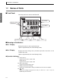
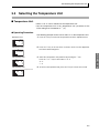
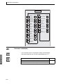
1.1 Names of Parts
■ Front Panel
The front panel is the same for the E5CN-FR.
No. 1 display
Operation indicators
No. 2 display
Level/Reset Key
Mode Key
Down Key
Up Key
■ Meanings of Indicators
● No. 1 Display
Displays the process value or parameter type.
Lights for approximately one second during startup.
● No. 2 Display
Displays the limit setting value, parameter operation read value, or the
variable input value.
Lights for approximately one second during startup.
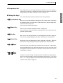
● Operation Indicators
1. ALM1 (Alarm 1)
Lights when the alarm 1 output is ON.
ALM2 (Alarm 2)
Lights when the alarm 2 output is ON.
2. OUT1 (Limit output)
Lights when the limit output is OFF.
3. CMW (Communications Writing)
Lights when communications writing is enabled and is out when it is disabled.
4.
(Key)
Lights when settings change protect is ON (i.e., when the U and D keys are
disabled by protected status.
1-2
1.1 Names of Parts
● Temperature Unit
The temperature unit is displayed when parameters are set to display a
unit” parameter set value. C indicates °C and F indicates °F.
■ Using the Keys
This section describes the basic functions of the front panel keys.
● O (Level)/Reset Key
Press this key to move between setting levels. The setting level is selected in
the following order: operation level: adjustment level, initial setting level,
communications setting level.
Can be used to reset the limit output.
● M (Mode) Key
Press this key to change parameters within a setting level.
The parameters can be reversed by holding down the key (moving one per
second in reverse order).
● U (Up) Key
Each press of this key increments the value displayed on the No. 2 display or
advances the setting. Holding the key down speeds up the incrementation.
● D (Down) Key
Each press of this key decrements values displayed on the No. 2 display or
reverses the setting. Holding the key down speeds up the incrementation.
● O + M Keys
Press these keys to change to the protect level. For details on operations
involving holding these keys down simultaneously, refer to 1.3 Setting Level
Configuration and Key Operations. For details on the protect level, refer to
SECTION 5 Parameters.
● O + U Keys
O + D Keys
To restrict set value changes (in order to prevent accidental or incorrect operations), these key operations require simultaneously pressing the O key along
with U or D key. This applies only to the parameter for the password to move
to protect level. (Refer to page 5-5.)
1-3
Introduction
temperature. The display is determined by the currently selected “temperature
SECTION 1 Introduction
Introduction
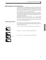
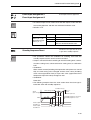
1.2 I/O Configuration and Main Functions
■ I/O Configuration
● E5CN-FR
Limit output
Limit output
External power
supply for ES1B
Temperature
input
Alarm 2
Control
section
Alarm output 2
Alarm 1
Alarm output 1
Event inputs
2 channels
Input error
Communications
function
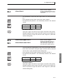
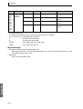
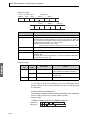
● Standard Models
Model number
Specifications
E5CN-FR2MT
100 to 240 VAC, thermocouple or platinum resistance thermometer input, 2 alarm outputs, 1 limit output
(Base model: E5CN-R2MT-500)
E5CN-FRMT
100 to 240 VAC, thermocouple or platinum resistance thermometer input, 1 limit output
(Base model: E5CN-RMT-500)
● Compatible Option Units
Model number
1-4
Specifications
E53-CNBN
Two event inputs
E53-CN03N
RS-485 communications interface
E53-CNPBN
Two event inputs and external power supply for ES1B
1.2 I/O Configuration and Main Functions
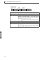
■ Main Functions
This section introduces the main E5CN-FR functions. For details on particular
following sections.
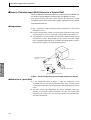
● Limit Control Function (Limit Output)
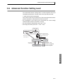
When a Temperature Controller is controlling the temperature of a furnace or
other heating device, a malfunction in the Temperature Controller may cause
the furnace temperature to rise, resulting in damage to the heated product or
the furnace itself.
When this situation occurs with the Limit Controller and the temperature rises
above the preset limit temperature (limit setting value), the limit output will go
OFF and the heater system circuit can be shut down to stop the heat source.
In addition, the limit output will remain OFF even when the temperature
returns to the normal range. A safer system can be constructed because the
limit output will remain OFF until it is reset manually.
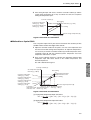
With the E5CN-FR Limit Controllers, it is possible to establish a lower limit
instead of an upper limit so that the limit function operates when the temperature falls below the limit setting value.
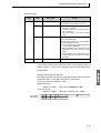
● Input Sensor Types
• The following input sensors can be connected for temperature input:
Thermocouple:
K, J, T, E, L, U, N, R, S, B
Infrared Thermosensor:
ES1B
10 to 70°C, 60 to 120°C, 115 to 165°C,
140 to 260°C
Platinum resistance thermometer: Pt100, JPt100
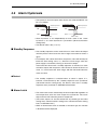
● Alarms
• Alarms can be used with the E5CN-FR2@@. Set the alarm classification and
alarm value or the alarm's upper and lower limits.
• If necessary, a more comprehensive alarm function can be achieved by
setting the standby sequence, alarm hysteresis, close in alarm/open in alarm,
and alarm latch parameters.
• When the “input error output” parameter is set to ON, the alarm 1 output turns
ON when an input error occurs.
● Event Inputs
• With the E5CN-FR@@B, the limit output can be cleared by an event input.
1-5
Introduction
functions and how to use them, refer to SECTION 3 Basic Operation and
SECTION 1 Introduction
● Communications Functions
• With the E5CN-FR@@03, communications functions utilizing CompoWay/F
(see note 1) or Modbus (see note 2) can be used.
Introduction
Note 1. CompoWay/F is an integrated general-purpose serial communications protocol developed by OMRON. It uses commands compliant
with the well-established FINS, together with a consistent frame
format on OMRON Programmable Controllers to facilitate communications between personal computers and components.
Note 2. Modbus is a communications control method conforming to the RTU
Mode of Modicon Inc.'s Modbus Protocol.
● External Power Supply for ES1B
• The E5CN-FR@@P can be used as the power supply for an ES1B Infrared
Thermosensor.
1-6
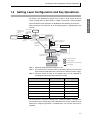
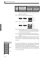
1.3 Setting Level Configuration and Key Operations
Parameters are divided into groups, each called a “level.” Each of the set
values (setting items) in these levels is called a “parameter.” The parameters
on the E5CN-FR Limit Controller are divided into the following seven levels.
When the power is turned ON, all of the display lights for approximately one
second.
Press the O +
M Keys for at
least 3 s.
(See note 3.)
Press the O
+ M keys;
display will
flash.
Power ON
Operation
Level
Protect level
Adjustment
Level
Press the
O Key less than 1 s.
Press the O+
M Keys for at
least 1 s.
Press the
O Key for
at least 1 s.
Press the O Key for at
least 1 s; display will
flash.
(See
note 1.)
Press the O Key
for at least 3 s.
Initial Setting Level
Press the O Key
for at least 1 s.
Control stops.
Communications Setting
Press the Level
O Key for less than 1 s.
Input password.
Set value −169
Advanced Function
Setting Level
Control in progress
(See
note 2.)
Control stopped
Input password.
Set value 1201
Not displayed for some models
Calibration Level
Level change
Note 1. Operation level entered for software reset.
Note 2. You cannot move to other levels by operating the keys on the front
panel from the calibration level. You must turn OFF the power supply.
Note 3. The time taken to move to the protect level can be adjusted by
changing the “Move to protect level time” setting.
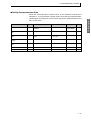
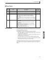
Level
Control in progress
Control stopped
Protect level
Can be set.
---
Operation level
Can be set.
---
Adjustment level
Can be set.
---
Initial setting level
---
Can be set.
Advanced function setting level
---
Can be set.
Calibration level
---
Can be set.
Communications setting level
---
Can be set.
Of these levels, the initial setting level, communications setting level,
advanced function setting level, and calibration level can be used only when
operation is stopped. Operation is stopped when any of these four levels is
selected.
1-7
Introduction
1.3 Setting Level Configuration and Key Operations
SECTION 1 Introduction
● Protect Level
• To switch from the operation level to the protect level, simultaneously hold
Introduction
down the O and M keys for at least 3 seconds. This level is for preventing
unwanted or accidental modification of parameters. Protected levels will not
be displayed, and so the parameters in that level cannot be modified.
● Operation Level
• The operation level is displayed when the power is turned ON. You can switch
from the operation level to either the protect level or adjustment level.
• Normally, select this level during operation. While operation is in progress,
items such as the PV and limit setting value can be monitored.
● Adjustment Level
• To move to the adjustment level, press the O key once (for less than 1 s).
• This level is for entering the limit setting value and shift values. Other settings
can be made as well, such as enabling/disabling write operations via communications, hysteresis settings, and input shift parameters. From the adjustment
level, it is possible to move to the top parameter of the initial setting level or
operation level.
● Initial Setting Level
• To move to the initial setting level from the adjustment level, press the O key
for at least 3 seconds. The No. 1 display flashes after one second. This level is
used to specify the temperature input type and set the alarm type. You can
move to the advanced function setting level or communications setting level
from this level. To return to the operation level, press the O key for at least
one second. To move to the communications setting level, press the O key for
less than one second.
(When moving from the initial setting level to the operation level, all the
indicators will light.)
● Advanced Function Setting Level
• To move to the advanced function setting level, set the “initial setting/communications protect” parameter in the protect level to 0 and then, in the initial
setting level, input the password (−169).
• From the advanced function setting level, it is possible to move to the
calibration level or to the initial setting level.
• This level is for setting the display auto-return time, event input assignments,
standby sequence, and alarm hysteresis, and it is the level for moving to the
user calibration.
● Communications Setting Level
• To move to the communications setting level from the initial setting level, press
the O key once (for less than 1 s). When using the communications function,
set the communications conditions in this level. Communications can be
established with a host computer (personal computer) in order to read/write
the limit setting value or monitor the PV from the computer.
1-8
1.3 Setting Level Configuration and Key Operations
● Calibration Level
• To move to the calibration level, input the password (1201) from the advanced
keys on the front panel. To cancel this level, turn the power OFF then back ON
again.
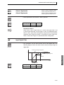
■ Selecting Parameters
• Within each level, the parameter is changed in order (or in reverse order) each
time the M key is pressed. (In the calibration level, however, parameters
cannot be changed in reverse order.) For details, refer to SECTION 5 Parameters.
Moves in order after M key
is pressed (if key is
released within 1 s).
While the M key is being held
down, the parameter will move
each second in reverse order.
Parameter 1
M
Parameter 2
Parameter 2
After M key has
been held down
for 2 s.
M
Parameter 3
Parameter 3
After M key
is pressed
Hold down the M key
during this interval.
After M key has
been held down
for 1 s.
Parameter 4
■ Fixing Settings
• If you press the M key at the final parameter, the display returns to the top
parameter for the current level.
• To change parameter settings, specify the setting using the U or D key, and
either leave the setting for at least two seconds or press the M key. This fixes
the setting.
• When another level is selected after a setting has been changed, the contents
of the parameter prior to the change are fixed.
• When you turn the power OFF, you must first fix the settings (by pressing the
M key). The settings are sometimes not changed by merely pressing the U
or D keys.
1-9
Introduction
setting level. The calibration level is for offsetting error in the input circuit.
• You cannot move to other levels from the calibration level by operating the
SECTION 1 Introduction
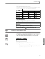
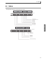
1.4 Communications Function
Introduction
The E5CN-FR is provided with a communications function that enables
parameters to be checked and set from a host computer. If the communications function is required, use a model that has that function (E5CNFR@@03). For details on the communications functions, see the Part 2:
Communications. Use the following procedure to move to the communications
setting level.
1. Press the O key for at least three seconds to move from the adjustment level to the
initial setting level.
2. Press the O key for less than one second to move from the initial setting level to the
communications setting level.
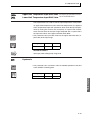
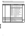
3. Select the parameters as shown below by pressing the M key.
4. Press the U or D key to change the parameter setting.
psel
Protocol setting
cwf
M
u-no
Communications Unit No.
1
M
bps
Communications baud rate
9.6
M
len
Communications data length
7 (See note.)
M
sbit
Communications stop bits
2 (See note.)
M
prty
Communications parity
even
M
sdwt
Send data wait time
20
M
Note:The “protocol setting” parameter is displayed only when CompoWay/F
communications are being used.
1-10
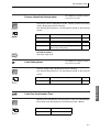
1.4 Communications Function
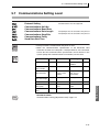
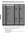
● Setting Communications Data
Match the communications specifications of the E5CN-FR and the host
specifications for all devices in the system (except the communications Unit
No.) are the same.
Parameter
Symbol
Setting (monitor) value
Selection symbols
cwf, mod
Default
Unit
CompoWay/
F (SYSWAY)
None
1
None
9.6
kbit/s
Protocol setting
psel
CompoWay/F (SYSWAY),
Modbus
Communications Unit
No.
u-no
0 to 99
Communications baud
rate
bps
1.2, 2.4, 4.8, 9.6, 19.2,
38.4
Communications data
length
len
7, 8
7
Bits
Communications stop
bits
sbit
1, 2
2
Bits
Communications parity
prty
None, Even, Odd
Even
None
Send data wait time
sdwe
0 to 99
20
ms
1.2, 2.4, 4.8, 9.6,
19.2, 38.4
none, even, odd
1-11
Introduction
computer. If a 1:N connection is being used, ensure that the communications
Introduction
SECTION 1 Introduction
1-12
SECTION 2
Preparations
This section describes the steps required before turning ON the power,
including settings, installation, and wiring.
2.1
2.2
Installation .................................................................... 2-2
Dimensions.............................................................. 2-2
Panel Cutout............................................................ 2-2
Mounting.................................................................. 2-3
Removing the E5CN-FR from the Case .................. 2-4
Wiring Terminals ........................................................... 2-5
Terminal Arrangement............................................. 2-5
Precautions when Wiring......................................... 2-5
Wiring ...................................................................... 2-6
2-1
SECTION 2 Preparations
2.1 Installation
■ Dimensions
(Unit: mm)
● E5CN-FR
(97)
91
44.8 × 44.8
44.8 × 44.8
48.8
58
78
Preparations
48 × 48
6
48
Terminal Cover (E53-COV10, sold separately)
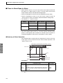
■ Panel Cutout
(Unit: mm)
Individual Mounting
Group Mounting
(48 × number of Units − 2.5) +1.0
45 +0.6
0
45
+0.6
0
45
+0.6
0
60 min.
0
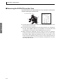
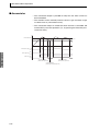
• Waterproofing is not possible when group mounting several Controllers.
• The recommended panel thickness is 1 to 5 mm.
• Units must not be closely mounted vertically. (Observe the recommended mounting space limits.)
• When group mounting several Controllers, ensure that the surrounding
temperature does not exceed the ambient operating temperature listed
in the specifications.
2-2
2.1 Installation
■ Mounting
For the Wiring Socket, purchase the P2CF-11 or PG3A-11 separately.
Terminal Cover
Preparations
Adapter
Waterproof packing
Panel
● Mounting to the Panel
1. For waterproof mounting, waterproof packing must be installed on the
Controller. Waterproofing is not possible when group mounting several
Controllers.
2. Insert the E5CN-FR into the mounting hole in the panel.
3. Push the adapter from the terminals up to the panel, and temporarily fasten
the E5CN-FR.
4. Tighten the two fastening screws on the adapter. Alternately tighten the two
screws little by little to maintain a balance. Tighten the screws to a torque of
0.29 to 0.39 N·m.
● Mounting the Terminal Cover
For the E5CN-FR, be sure that the "UP" mark is facing up, and then fit
the terminal cover into the holes on the top and bottom.
2-3
SECTION 2 Preparations
■ Removing the E5CN-FR from the Case
The E5CN-FR can be removed from the case to perform maintenance
without removing the terminal leads.
Tool insertion hole
Flat-blade screwdriver
(Unit: mm)
20 min.
(1)
(3)
(2)
Preparations
(1)
1. Insert the tool into the two tool insertion holes (one on the top and one on the
bottom) and release the hooks.
2. Insert the tool in the gap between the front panel and rear case, and pull out
the front panel slightly. Hold the top and bottom of the front panel and
carefully pull it out toward you, without applying unnecessary force.
3. When inserting the E5CN-FR, check to make sure that the waterproof
packing is in place and push the E5CN-FR toward the rear case until it snaps
into position. While pushing the E5CN-FR into place, push down on the
hooks on the top and bottom surfaces of the rear case so that the hooks are
securely locked in place. Be sure that electronic components do not come
into contact with the case.
2-4
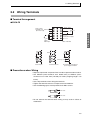
2.2 Wiring Terminals
2.2 Wiring Terminals
■ Terminal Arrangement
● E5CN-FR
Alarm output
Relay output
250 VAC, 3 A Limit output
(Resistive load)
Alarm 2
Preparations
Alarm 1/input error
A
B
Input power supply
B
TC/Pt
Multi-input
EV1
100 to 240 VAC
B
RS-485
A
EV1
EV2
DO NOT
USE
DO NOT
USE
DO NOT
USE
DO NOT
USE
DO NOT
USE
−
Communications
Event inputs and external
power supply for ES1B
Event inputs
+
EV2
External power supply
■ Precautions when Wiring
• Separate input leads and power lines in order to prevent external noise.
• Use AWG24 (cross-sectional area: 0.205 mm2) to AWG14 (crosssectional area: 2.081 mm2) twisted-pair cable (stripping length: 5 to
6 mm).
• Use crimp terminals when wiring the terminals.
• Tighten the terminal screws to a torque of 0.74 to 0.90 N·m.
• Use the following types of crimp terminals for M3.5 screws.
7.2 mm max.
7.2 mm max.
• Do not remove the terminal block. Doing so may result in failure or
malfunction.
2-5
SECTION 2 Preparations
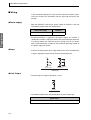
■ Wiring
In the connection diagrams, the left side of the terminal numbers represents the inside of the Controller and the right side represents the
outside.
● Power supply
• With the E5CN-FR, connect the power supply to terminals 9 and 10.
The following table shows the specifications.
Input power supply
E5CN-FR
Preparations
100 to 240 VAC, 50/60 Hz
7.5 VA
• Standard insulation is applied to the power supply I/O sections. If
reinforced insulation is required, connect the input and output terminals
to a device without any exposed current-carrying parts or to a device
with standard insulation suitable for the maximum operating voltage of
the power supply I/O section.
● Input
• Connect the temperature input using terminals 3 to 5 for the E5CN-FR,
using the appropriate terminals for the input type being used.
Platinum resistance
thermometer
Thermocouple
E5CN-FR
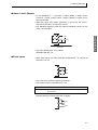
● Limit Output
• The limit output is output at terminals 1 and 2.
Relay
E5CN-FR
• The following table shows the specifications for each output type.
Specifications
250 VAC, 3A (resistive load), electrical durability: 100,000 operations
2-6
2.2 Wiring Terminals
● Alarm 1 and 2 Outputs
• On the E5CN-FR@@@, the alarm 1 output (ALM1) is output across
terminals 7 and 8, and the alarm 2 output (ALM2) is output across
terminals 6 and 8.
• When the “input error output” parameter is set to ON, the alarm 1
output turns ON when an input error occurs.
• The following diagrams show the internal equalizing circuits for the
alarm 1 and 2 outputs.
Preparations
ALM2
ALM1, input error
E5CN-FR
• The relay specifications are as follows:
SPST-NO 250 VAC 1 A
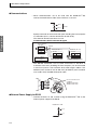
● Event Inputs
• When event inputs are to be used with the E5CN-FR@@B, connect to
terminals 11 to 13.
EV1
EV2
E5CN-FR@@B
• Use event inputs under the following conditions:
• The outflow current is approximately 7 mA.
Contact input
ON: 1 kΩ max., OFF: 100 kΩ min.
No-contact input ON: Residual voltage 1.5 V max.; OFF: Leakage current
0.1 mA max.
Polarities during no-contact input are as follows:
11 −
12 +
13 +
EV1
EV2
2-7
SECTION 2 Preparations
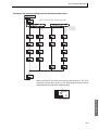
● Communications
• When communications are to be used with the E5CN-FR@@03,
connect communications cable across terminals 11 and 12.
11
B (+)
12
A (−)
RS-485
E5CN-FR@@03
Specify both ends of the transmission path including the host computer
Preparations
as end nodes (that is, connect terminators to both ends).
The minimum terminal resistance is 54 Ω.
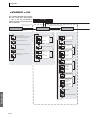
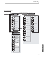
Communications Unit Connection Diagram
Host computer
RS-485
−
+
FG
Shield
E5CN-FR (No. 1)
No.
A < B: [1] Mark
A > B: [0] Space
E5CN-FR (No. 31)
RS-485
RS-485
No.
Abbreviation
Abbreviation
12
A (−)
12
A (−)
11
B (+)
11
B (+)
Terminator (120 Ω, 1/2 W)
• The RS-485 connection can be either one-to-one or one-to-N. A
maximum of 32 Units (including the host computer) can be connected
in one-to-N systems. The maximum total cable length is 500 m. Use
AWG24 (cross-sectional area: 0.205 mm2) to AWG14 (cross-sectional
area: 2.081 mm2) shielded twisted-pair cable.
Cross-sectional area of
conductor
AWG24: 0.205 mm2
AWG14: 2.081 mm2
● External Power Supply for ES1B
• Connect terminals 14 and 15 when using the E5CN-FR@@PB as the
external power supply for the ES1B.
E5CN-FR@@PB
(+)
(−)
2-8
2.2 Wiring Terminals
• The following table provides the specifications of the external power
supply for ES1B.
Output voltage
12 VDC ±10%
Output current
20 mA max.
• Contact your OMRON representative for information on using the
Preparations
external power supply for ES1B for other applications.
2-9
Preparations
SECTION 2 Preparations
2-10
SECTION 3
Basic Operation
This section provides specific examples to explain the basic operation of the
E5CN-FR Limit Controller.
3.1
3.2
3.3
3.4
3.5
Initial Setting Examples ................................................ 3-2
Setting the Input Type ................................................... 3-3
Input Type................................................................ 3-3
Selecting the Temperature Unit .................................... 3-5
Temperature Unit..................................................... 3-5
Using the Limit Controller Function............................... 3-6
Selecting Upper/Lower Limit.................................... 3-6
Changing the Limit Setting Value ............................ 3-7
Resetting the Limit Output ....................................... 3-8
Alarm Outputs............................................................... 3-9
Alarm Types ............................................................ 3-9
Alarm Values ......................................................... 3-10
Annunciator ........................................................... 3-12
3-1
SECTION 3 Basic Operation
3.1 Initial Setting Examples
The initial hardware setup, including the sensor input type, alarm types,
and other settings are made with the parameter displays. The O and
M keys are used to switch between parameters, and the amount of
time that you press the keys determines which parameter you move to.
This section describes a typical application example.
● Explanation of Examples
Changing Parameters
A
image means that there are parameters.
Continue pressing the M key to change parameters
until you reach the intended parameter.
Changing Numbers
Basic Operation
Numeric data and selections in each screen
can be changed by using the U and D keys.
● Typical Example
Setup Procedure
Power ON
Power ON
Operation
Level
Input type: 5 (K thermocouple,
−300°F to 2,300°F)
Selecting Upper/Lower Limit:
Upper limit
Alarm 1 type:
12 Annunciator
Limit setting value: 100°F
PV/Limit setting value
Press the O key for less than 1 s.
Adjustment
Level
Adjustment level
display
Press the O key for
at least 3 s.
Control stops.
Initial Setting
Level
Initial Setting
Level
Check input type.
Input type: 5
Set input specifications
Set the limit as
an upper or
lower limit.
Set limit specifications.
Selecting Upper/
Lower Limit hi
Check alarm type.
Alarm 1 type: 12
Set alarm type
Press the O key for
at least 1 s.
Operation starts.
Operation
Level
F
Adjustment
Level
Set limit setting value
Start operation
Press the O key
for less than 1 s.
Adjustment
Level
Use the U and D
keys to set the limit
setting value to
100 °F.
PV/Limit setting value
F
Limit setting value
Start operation.
3-2
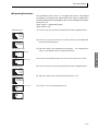
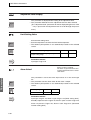
3.2 Setting the Input Type
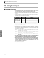
3.2 Setting the Input Type
The Controller suppor ts three input types: platinum resistance
thermometer, thermocouple, and infrared thermosensor inputs. Set the
input type that matches the sensor that is used.
■ Input Type
The following example shows how to set a K thermocouple for 0.0 to
900.0°F.
● Operating Procedure
1. Press the O key to move from the operation level to the adjustment level.
Operation Level
F
25
0
level to the initial setting level.
l.adj
3. Press the U key to enter the set value of the desired sensor.
Initial Setting Level
in-t
Input type
When you use a K thermocouple (0.0 to 900.0°F), enter 6 as the set value.
5
Hint: The key operation is fixed two seconds after the change, or by
in-t
pressing the O or M key.
6
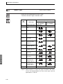
List of Input Types
Input type
Platinum resistance thermometer
Specifications
Set value
Pt100
0
−200 to 850 (°C)/−300 to 1,500 (°F)
1
−199.9 to 500.0 (°C)/−199.9 to 900.0 (°F)
2
0.0 to 100.0 (°C)/0.0 to 210.0 (°F)
3
−199.9 to 500.0 (°C)/−199.9 to 900.0 (°F)
4
0.0 to 100.0 (°C)/0.0 to 210.0 (°F)
JPt100
Input temperature setting range
3-3
Basic Operation
2. Press the O key for at least three seconds to move from the adjustment
Adjustment Level
SECTION 3 Basic Operation
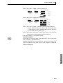
Input type
Thermocouple
Specifications
Set value
K
5
−200 to 1,300 (°C)/−300 to 2,300 (°F)
6
−20.0 to 500.0 (°C)/0.0 to 900.0 (°F)
7
−100 to 850 (°C)/−100 to 1,500 (°F)
8
−20.0 to 400.0 (°C)/0.0 to 750.0 (°F)
9
−200 to 400 (°C)/−300 to 700 (°F)
10
−199.9 to 400.0 (°C)/−199.9 to 700.0 (°F)
E
11
0 to 600 (°C)/0 to 1,100 (°F)
L
12
−100 to 850 (°C)/−100 to 1,500 (°F)
U
13
−200 to 400 (°C)/−300 to 700 (°F)
14
−199.9 to 400.0 (°C)/−199.9 to 700.0 (°F)
N
15
−200 to 1,300 (°C)/−300 to 2,300 (°F)
R
16
0 to 1,700 (°C)/0 to 3,000 (°F)
S
17
0 to 1,700 (°C)/0 to 3,000 (°F)
B
18
100 to 1,800 (°C)/300 to 3,200 (°F)
10 to 70°C
19
0 to 90 (°C)/0 to 190 (°F)
60 to 120°C
20
0 to 120 (°C)/0 to 240 (°F)
115 to 165°C
21
0 to 165 (°C)/0 to 320 (°F)
140 to 260°C
22
0 to 260 (°C)/0 to 500 (°F)
J
Basic Operation
T
ES1B Infrared
Themosensor
Input temperature setting range
• The default is 5.
• If a platinum resistance thermometer is mistakenly connected while a
setting for other than a platinum resistance thermometer is in effect,
s.err will be displayed. To clear the s.err display, check the wiring and
then turn the power OFF and back ON.
3-4
3.3 Selecting the Temperature Unit
3.3 Selecting the Temperature Unit
■ Temperature Unit
• Either °C or °F can be selected as the temperature unit.
• Set the temperature unit in the “temperature unit” parameter of the
initial setting level. The default is F (°F).
● Operating Procedure
1. Press the O key to move from the operation level to the adjustment level.
Operation Level
F
The following example shows how to select °C as the temperature unit.
25
0
2. Press the O key for at least three seconds to move from the adjustment
Adjustment Level
Initial Setting Level
Press the U or D key to select either °C or °F.
C: °C
F: °F
in-t
5
Initial Setting Level
d-u
3. Select the “temperature unit” parameter by pressing the M key.
4. To return to the operation level, press the O key for at least one second.
Temperature unit
c
3-5
Basic Operation
level to the initial setting level.
l.adj
SECTION 3 Basic Operation
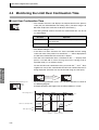
3.4 Using the Limit Controller Function
When the measured temperature (PV) exceeds the limit setting value,
the limit output relay turns OFF and the OUT1 operation indicator turns
ON. If the limit output relay turns OFF (limit alarm is ON), the limit
output relay will remain OFF until the operator checks operation
(performs resetting operation).
Before power
is turned ON
Limit output relay ON
Limit output relay OFF
Temperature in furnace
Limit setting value
Hysteresis
Basic Operation
Control SP
Power ON
Malfunction
■ Selecting Upper/Lower Limit
• The upper/lower limit selection setting enables switching between upper
limit and lower limit operation.
• The default setting is for upper limit operation (high limit).
● Operating Procedure
The following example shows how to select either upper or lower limit
operation.
1. Press the O key to move from the operation level to the adjustment level.
Operation Level
F
Adjustment Level
2. Press the O key for at least three seconds to move from the adjustment
level to the initial setting level.
Initial Setting Level
Switching Upper/
Lower Limit
3. Press M key to select the Selecting Upper/Lower Limit setting.
4. Press the U or D key to select either upper (hi) or lower (lo) limit
operation.
5. To return to the operation level, press the O key for at least one second.
3-6
3.4 Using the Limit Controller Function
■ Changing the Limit Setting Value
• The operation level is displayed when the power is turned ON. The PV
is shown on the No. 1 display and the limit setting value is shown in the
bottom par t of the display, but the limit setting value can only be
monitored in the operation level. The limit setting value can be changed
on the adjustment level's Limit Setting Value display.
• It is not possible to switch to the adjustment level unless the "operation/
adjustment protect" parameter is set to 0, so this parameter must be set
to 0 in order to change the limit setting value. For details, refer to 4.8
Using the Key Protect Level.
• To change the limit setting value, press the U or D key in the "limit
setting value" parameter (in the adjustment level), and set the desired
set value. The new limit setting value will become effective two seconds
after you have specified the new value.
In this example, the limit setting value is changed from 0°F to 200°F.
Normally, the "process value/limit setting value" parameter is displayed.
The limit setting value is 0°F.
Operation Level
1. Press the O key to move from the operation level to the adjustment level.
F
Adjustment Level
F
2. Press the M key to select the "limit setting value" parameter.
3. Use the U and D keys to set the limit setting value to 200°F.
Limit setting value
F
3-7
Basic Operation
● Operating Procedure
SECTION 3 Basic Operation
■ Resetting the Limit Output
• When the Controller is in the operation level, the limit output can be
reset by pressing the Level/Reset Key for more than one second.
• The limit output reset operation resets the limit output and also resets
the annunciator alarm.
Note 1. If the limit status is OFF, the limit output will be reset and the
limit output relay will go ON.
If the limit status is still ON (i.e., if the PV still exceeds the limit
setting value), the limit output will not be reset.
Note 2. The annunciator alarm will be turned OFF regardless of the
limit status.
Note 3. When the limit output is being reset with an event input, the
event input can be received in the operation level, adjustment
level, or protect level.
Basic Operation
Example Operation with an Upper (High) Limit
Limit setting value
Hysteresis
Limit status
ON
OFF
Annunciator output
Limit output relay
ON
OFF
ON
OFF
(1) Reset
operation
(Cannot be
performed.)
(2) Reset
operation
(Can be
performed.)
(3) Reset
operation
(Cannot be
performed.)
● Operating Procedure
The following example shows how to clear the limit output.
Operation level
(Monitor only.)
F
Limit setting value
F
PV/Limit setting value
Limit over
continuation time
3-8
F
Limit over
maximum value
F
Limit over
minimum value
Press O key
for at least 1 s.
The limit output
is reset.
3.5 Alarm Outputs
3.5 Alarm Outputs
• The alarm can be used in the E5CN-FR2@@@ (equipped with 2
alarms).
Alarm outputs are determined by a combination of “alarm type,” “alarm
value,” and “alarm hysteresis” alarm output conditions. For details, refer
to 4.2 Alarm Hysteresis.
• This section describes the “alarm type,” “alarm value,” “upper-limit
alarm” and “lower-limit alarm” parameters.
■ Alarm Types
Alarm output operation
Alarm type
When alarm value
X is positive
0
Alarm function OFF
Output OFF
1 (See
note 1.)
Upper- and lower-limit
(deviation)
ON
OFF
2
Upper-limit (deviation)
3
Lower-limit (deviation)
5 (See
note 1.)
Upper- and lower-limit
with standby
sequence (deviation)
ON
OFF
Upper-limit with
standby sequence
(deviation)
ON
OFF
Lower-limit with
standby sequence
(deviation)
ON
OFF
7
8
9
10
11
X
SP
X
ON
OFF
Upper- and lower-limit
range (deviation)
See note 2.
SP
ON
OFF
4 (See
note 1.)
6
L H
When alarm value
X is negative
Basic Operation
Set
value
SP
L H
ON
OFF
ON
OFF
ON
OFF
X
SP
X
SP
See note 3.
SP
L H
See note 4.
SP
See note 5.
Absolute-value upperlimit
ON
OFF
Absolute-value lowerlimit
ON
OFF
Absolute-value upperlimit with standby
sequence
ON
OFF
Absolute-value lowerlimit with standby
sequence
ON
OFF
X
SP
X
SP
X
0
X
0
X
0
X
0
ON
OFF
ON
OFF
ON
OFF
ON
OFF
ON
OFF
ON
OFF
X
SP
X
SP
X
0
X
0
X
0
X
0
3-9
SECTION 3 Basic Operation
Alarm output operation
Set
value
12
Alarm type
When alarm value
X is positive
Annunciator
When alarm value
X is negative
---
Note 1. With set values 1, 4, and 5, the upper- and lower-limit values
can be set independently for each alar m type, and are
expressed as “L” and “H.”
Note 2. Set value: 1 (Upper- and lower-limit alarm)
Case 1
Case 2
Case 3 (Always ON)
H < 0, L < 0
L
H SP
H < 0, L > 0
|H| < |L|
H
SP L H
H > 0, L < 0
|H| > |L|
H
SP
L
H < 0, L > 0
|H| ≥ |L|
L SP
SP H
L
H > 0, L < 0
|H| ≤ |L|
Note 3. Set value: 4 (Upper- and lower-limit range)
Case 2
Basic Operation
Case 1
Case 3 (Always OFF)
H < 0, L < 0
L
H SP
H < 0, L > 0
|H| < |L|
SP L
H
H
H > 0, L < 0
|H| > |L|
H
SP
L
L SP
SP H L
H < 0, L > 0
|H| ≥ |L|
H > 0, L < 0
|H| ≤ |L|
Note 4. Set value: 5 (Upper- and lower-limit with standby sequence)
• For the lower-limit alarms in cases 1 and 2 above, the alarm
is always OFF if upper- and lower-limit hysteresis overlaps.
• In case 3, the alarm is always OFF.
Note 5. Set value: 5 (Upper- and lower-limit with standby sequence)
• The alarm is always OFF if upper- and lower-limit hysteresis
overlaps.
• Set the alarm type independently for each alarm in the “alarm 1 and 2
type” parameters in the initial setting level. The default settings are
Alarm 1 Type = 12 (annunciator alarm) and Alarm 2 Type = 2 (upper
limit alarm).
■ Alarm Values
al1l
al2l
al1h
al2h
al-1
al-2
3-10
Alarm lower
limit value
• Alarm values are indicated by “X” in the table on the previous page.
When the upper and lower limits are set independently, “H” is displayed
for upper limit values, and “L” is displayed for lower limit values.
• To set the alarm value upper and lower limits for deviation, switch to the
Alarm upper
limit value
adjustment level, set the upper limits in the "alarm value upper limit 1
and 2" parameters, and set the lower limits in the "alarm value lower
limit 1 and 2" parameters.
Alarm value
3.5 Alarm Outputs
● Operating Procedure
This procedure sets alarm 1 as an upper-limit alarm. The related
parameters and settings are shown below. The alarm is output when
the limit setting value is exceeded by 10°F. (In this example, the temperature unit is °F.)
Alarm 1 type = 2 (Upper-limit alarm)
Alarm value 1= 10
1. Press the O key to move from the operation level to the adjustment level.
Operation Level
F
25
100
2. Press the O key for at least three seconds to move from the adjustment
Adjustment Level
level to the initial setting level.
Initial Setting Level
in-t
Input type
alt1
Alarm 1 type
3. Select the "alarm 1 type" parameter by pressing the M key. Change the set
value to 2. The default value is 12 (Annunciator alarm).
5
4. To return to the operation level, press the O key for at least one second.
2
5. Press the O key to move from the operation level to the adjustment level.
Operation Level
F
25
100
6. Select the “alarm value 1” parameter by pressing the M key.
Adjustment Level
l.adj
F
al-1
Alarm value 1
7. Use the U key to set the parameter to 10.
0
F
al-1
10
3-11
Basic Operation
l.adj
SECTION 3 Basic Operation
■ Annunciator
• The annunciator output is provided to notify the user when a limit has
been exceeded.
• This function can be used only when the alarm 1 type and alarm 2 type
are both set to 12 (annunciator alarm).
• The annunciator output is turned ON when the limit is exceeded and
turned OFF by the reset operation (i.e., by pressing the Reset Key for 1
second or more).
Limit setting value
Hysteresis
Basic Operation
Annunciator output ON
OFF
Limit output relay ON
OFF
Limit status
ON
OFF
(1) Reset operation
(Annunciator output OFF)
(3) Reset operation
(Annunciator output OFF)
(2) Reset operation
(Annunciator output already OFF)
3-12
SECTION 4
Applications Operations
This section describes each function in detail to help make the most of the
E5CN-FR Limit Controller's functionality and capabilities.
4.1
4.2
4.3
4.4
4.5
4.6
4.7
4.8
4.9
Shifting Input Values ..................................................... 4-2
Shifting Inputs.......................................................... 4-2
How to Calculate Input Shift Values for a
2-point Shift ............................................................. 4-4
Alarm Hysteresis .......................................................... 4-7
Standby Sequence .................................................. 4-7
Using Event Inputs...................................................... 4-10
Alarm Latch ............................................................. 4-7
Close in Alarm/Open in Alarm ................................. 4-8
Event Input Functions............................................ 4-10
Monitoring the Limit Over Continuation Time ............. 4-12
Limit Over Continuation Time ................................ 4-12
Monitoring the Limit Over Minimum/Maximum Value.. 4-14
Limit Over Minimum/Maximum Value.................... 4-14
Setting the Limit Output Operation at Startup............. 4-15
Restart Mode ......................................................... 4-15
Moving to the Advanced Function Setting Level......... 4-17
Using the Key Protect Level........................................ 4-19
Protection .............................................................. 4-19
Entering the Password to Move to the
Protect Level.......................................................... 4-20
Communications Operation Command to
Move to the Protect Level...................................... 4-22
PV Change Color........................................................ 4-23
PV Color Change Function.................................... 4-23
Setting ................................................................... 4-23
4-1
SECTION 4 Applications Operations
4.1 Shifting Input Values
■ Shifting Inputs
The input shift matched to the sensor currently selected in the “input
type” parameter is displayed.
Input type
Input type
set value
Shift method
Related parameters
Resistance thermometer or thermocouple input
0 to 18
One-point shift
Temperature input shift
value
Infrared Thermosensor
19 to 22
Two-point shift
Upper-limit temperature input shift value
Lower-limit temperature input shift value
● One-point shift
ins
Temperature
input shift
• With a 1-point shift, the value set for the “temperature input shift”
parameter (adjustment level) is applied to each point in the entire
temperature input range. For example, if the input shift value is set to
1.2°C, the process value is treated as 201.2°C after the input shift is
applied when the measured process value is 200°C.
Temperature
Applications
Operations
Upper limit
After shifting
Lower limit
Before
shifting
Input shift value
Input
0
100
4-2
4.1 Shifting Input Values
● Operating Procedure
1. Press the O key to move from the operation level to the adjustment level.
Operation Level
C
In this example, the input from a K sensor is shifted by 1°C.
30
200
2. Select the “temperature input shift” parameter by pressing the M key.
Adjustment Level
l.adj
C
ins
Temperature
input shift
3. Press the U or D key to set 1.0.
0.0
C
ins
4. To return to the operation level, press the O key. The process value is 1°C
larger than before the shift was applied.
1.0
Operation Level
C
31
200
● Two-point shift
insl
Lower-limit
temperature input
shift value
• With an infrared thermosensor, separate shift values can be set for the
upper limit and lower limit of the sensor input range. If different shift
values are set for the upper limit and lower limit, then the slope of the
line will be different before and after applying the input shift. For
example, if the upper-limit value is set to 2°C and the lower-limit value is
set to 1° C, the input temperature will be shifted by 1.5 ° C for a 50%
input, i.e., by the average of the upper-limit and lower-limit values.
• Set the upper-limit value in the “upper-limit temperature input shift
value” parameter and the lower-limit value in the “lower-limit temperature input shift value” parameter.
Temperature
Upper-limit temperature
input shift value
Upper limit
After shifting
Before shifting
Lower limit
0
Input
Lower-limit temperature 100
input shift value
4-3
Applications
Operations
insh
Upper-limit
temperature input
shift value
SECTION 4 Applications Operations
■ How to Calculate Input Shift Values for a 2-point Shift
When an ES1B Infrared Thermosensor is connected to the E5CN-FR,
an offset of several degrees to several tens of a degree can occur.
This offset occurs because a bias current for detecting a Limit
Controller sensor error flows to the output impedance of the ES1B
Infrared Thermosensor.
● Preparations
1. Set a temperature range matching the input specifications of the infrared
temperature sensor.
2. Prepare a thermometer capable of measuring the temperature of the control
target as shown in so that a 1-point shift or 2-point shift can be carried out.
3. The E5CN-FR@@PB have a built-in external power supply for ES1B Infrared
Thermosensors. These E5CN models can be used as the power supply
when using ES1B. When ES1B are used with other E5CN models, provide a
separate power supply for the Infrared Thermosensors.
Applications
Operations
Infrared Temperature
Sensor
(C) Control target
Power supply
(B) Thermometer
Output
(A) E5CN-FR Limit Controller
Figure 1 Offset Configuration for an Infrared Temperature Sensor
● Method for a 1-point Shift
1. In the configuration shown in Figure 1, adjust the temperature of the
controlled system so that it is near the limit setting value. Assume that the
control target temperature (C) and the thermocouple temperature (B) are the
same.
2. Check the control target temperature (B) and the Controller readout (A).
Subtract the Controller readout temperature (A) from the control target
temperature (B), and set insl and insh to the result as the input shift value.
The shift is illustrated in .
4-4
4.1 Shifting Input Values
3. After setting the input shift values, check the Controller readout (A) and the
control target temperature (B). If they are almost the same, this completes
shifting the temperature input.
Controller readout (A)
After shifting
Controller readout after
shifting (e.g., 120°C)
Controller readout before
shifting (e.g., 110°C)
0
Input shift value (e.g., 10°C)
Before shifting
Near limit setting
value (e.g., 120°C)
Control target temperature (B)
Figure 2 Illustration of 1-Point Shift
● Method for a 2-point Shift
Use a 2-point input shift if you want to increase the accuracy of the
readout values across the range of the sensor.
1. Adjust the Controller readout at two points, one near room temperature and
the other near the limit setting value temperature. To adjust the temperatures,
it is necessary to check the Controller readout (A) and the temperature of the
controlled system (B) with the controlled system's temperature near room
temperature and near the set point.
2. Then use the following formulas to calculate the upper-limit and lower-limit
Applications
Operations
temperature input shift values based on the readout temperatures and
desired temperatures.
The shift is illustrated in Figure 3.
Controller readout (A)
Set temperature upper
limit YH (e.g., 260°C)
Controller readout after
shifting (e.g., 110°C)
Controller readout before
shifting (e.g., 105°C)
After shifting
Upper-limit temperature
input shift value insh
Before shifting
Controller readout before
shifting (e.g., 40°C)
Controller readout after
Control target temperature (B)
0 X1 Room tempershifting (e.g., 25°C)
ature
(e.g.,
25°C)
Lower-limit
X2 Near limit setting
temperature input Set temperature lower
value (e.g., 110°C)
shift value insl limit YL (e.g., 0°C)
Figure 3 Illustration of 2-Point Shift
(1) Lower-limit temperature input shift value
YL − Y1
insl =
× {(X2 − Y2) − (X1 − Y1)} + (X1 − Y1) (ºC)
Y2 − Y1
(2) Upper-limit temperature input shift value
YH − Y1
insh =
× {(X2 − Y2) − (X1 − Y1)} + (X1 − Y1) (ºC)
Y2 − Y1
4-5
SECTION 4 Applications Operations
3. After setting the calculated values to insl and insh, check the Limit
Controller readout (A) and control target temperature (B).
4. Here, offsets are set at two points, near room temperature and near the limit
setting value. To improve accuracy within the temperature measurement
range, another point in the measurement temperature range other than the
limit setting value should be set instead of room temperature.
● Example of a 2-point Temperature Input Shift
In this example, we use the ES1B with a 0 to 260°C specification. In
equations 1 and 2, the set temperature lower limit YL is 0°C and the set
temperature upper limit YH is 260 ° C. Check the temperature of the
control target.
The temperature input shift values can be calculated as shown below
when the Limit Controller readout Y1 is 40°C for a room temperature X1
of 25 ° C and when the Limit Controller readout Y2 is 105 ° C for a
Temperature near limit setting value X2 of 110°C.
Lower-limit Temperature Input Shift Value
C
insl
-27.3
C
insh
Applications
Operations
52.7
4-6
Lower-limit
temperature
input shift value
Upper-limit
temperature
input shift value
insl =
0 − 40
× {(110 − 105) − (25 − 40)} + (25 − 40) = −27.3 (°C)
105 − 40
Upper-limit Temperature Input Shift Value
260 − 40
insh =
× {(110 − 105) − (25 − 40)} + (25 − 40) = 52.7 (°C)
105 − 40
4.2 Alarm Hysteresis
4.2 Alarm Hysteresis
• The hysteresis of alarm outputs when alarms are switched ON/OFF can
be set as follows:
Upper-limit alarm
Alarm hysteresis
ON
Lower-limit alarm
Alarm hysteresis
ON
OFF
OFF
Alarm value
Alarm value
• Alarm hysteresis is set independently for each alarm in the “alarm
hysteresis 1" to “alarm hysteresis 2” parameters (advanced function
setting level).
• The default value is 0.2 (°C or °F).
■ Standby Sequence
• The standby sequence can be used so that an alarm will not be output
until the process value leaves the alarm range once and then enters it
again.
• For example, with a lower limit alarm, the process value will normally be
below the limit setting value, i.e., within the alarm range, when the
power supply is turned ON, causing an alarm to be output.
will not be output until the process value increases above the alarm set
value, i.e., until it leaves the alarm range, and then falls back below the
alarm set value.
● Restart
• The standby sequence is canceled when an alarm is output. It is,
however, restarted later by the “standby sequence reset” parameter
(advanced function setting level). For details, refer to the “standby
sequence reset” parameter in SECTION 5 Parameters.
■ Alarm Latch
• The alarm latch can be used to keep the alarm output ON regardless of
the temperature once the alarm output has turned ON. The alarm
output will turn OFF when the power is turned OFF.
• (The alarm output can also be turned OFF by switching to the initial
setting level, communications setting level, advanced function setting
level, or calibration level.)
• When an Annunciator alarm is selected as the alarm type, this function
is disabled and not displayed.
4-7
Applications
Operations
If the lower limit alarm with a standby sequence is selected, an alarm
SECTION 4 Applications Operations
■ Close in Alarm/Open in Alarm
• When “close in alarm” is set, the status of the alarm output function will
be output as is. When “open in alarm” is set, the status of the alarm
output function will be reversed before being output.
• Close in alarm/open in alarm can be set separately for each alarm.
• Close in alarm/open in alarm is set in the “alarm 1 open in alarm” to
“alarm 2 open in alarm” parameters (advanced function setting level).
• The default is n-o (close in alarm).
Setting
Alarm status
Close in alarm
Open in alarm
Alarm indicator
Alarm output
ON
Lit
ON
OFF
Not lit
OFF
ON
Lit
OFF
OFF
Not lit
ON
• The alarm outputs will turn OFF (i.e., the relay contacts will open) when
power is interrupted and for about two seconds after the power is
turned ON regardless of the close in alarm/open in alarm setting.
● Summary of Alarm Operation
The following figure summarizes the operation of alarms when the
alarm type is set to “lower-limit alarm with standby sequence” and
“close in alarm” is set.
Applications
Operations
Alarm type: Lower-limit alarm with standby sequence
PV
Alarm value
Alarm hysteresis
Time
Standby sequence
canceled
Alarm
ON
OFF
ON (closed)
Output
OFF (open)
Parameters
Symbol
alh*
rest
al*n
* = 1 to 2
4-8
Parameter: Level
Alarm 1 to 2 hysteresis: Advanced function setting
level
Standby sequence: Advanced function setting level
Alarm 1 to 2 open in alarm: Advanced function setting level
Description
Alarm
Alarm
Alarm
4.2 Alarm Hysteresis
● Alarm Operation for Sensor Error and Display Range Exceeded
The following alarm operation will be performed when there is an input
error or the value exceeds the display range.
Error
Alarm output
Operating at abnormally high temperature
Over lower-limit indication range
-lo-
Operating at abnormally low temperature
Over upper-limit indication range
-hi-
Operating at abnormally high temperature
Applications
Operations
Input error
s.err
4-9
SECTION 4 Applications Operations
4.3 Using Event Inputs
■ Event Input Functions
• An external input can be used to reset the limit output or clear the limit
over continuation time and limit over minimum/maximum value.
• There are two event inputs and each input can be assigned a separate
function.
• Assign functions to the event inputs with the "event input assignment 1"
and "event input assignment 2" parameters.
Setting item
Event input assignment 1 (ev-1) or
Event input assignment 2 (ev-2)
Set Value
Settings
none
None
rset
Reset limit output
hclr
Clear the limit over continuation time and
limit over minimum/maximum value.
• When one event input is set to rset or hclr, the other event input can
only be set to the other function.
• The limit output reset operation resets the limit output and also resets
the annunciator alarm. The operation is reset when the event input
changes from OFF to ON.
Note 1. If the limit status is OFF, the limit output will be reset and the
Applications
Operations
limit output relay will go ON.
Note 2. If the limit status is still ON (i.e., if the PV still exceeds the limit
setting value), the limit output will not be reset.
Note 3. The annunciator alarm will be turned OFF regardless of the
limit status.
• The limit over continuation time and the limit over minimum/maximum
value are cleared when the event input changes from OFF to ON.
• When an event input is used to clear the limit over continuation time and
the limit over minimum/maximum value, those values cannot be cleared
separately. (To clear one of these values independently, the value must
be cleared with the key operation.)
• The default setting is none.
4-10
4.3 Using Event Inputs
● Operating Procedure
The following example shows how to set event input assignment 1 to
rset (reset limit output).
1. Press the O key to move from the operation level to the adjustment level.
Operation Level
F
25
100
2. To return to the initial setting level, press the O key for at least three
Adjustment Level
seconds.
l.adj
Initial Setting Level
in-t
Input type
3. Press the M key to select the "move to advanced function setting level"
parameter.
5
4. Use the U and D keys to input −169.
amov
Move to the advanced function setting level by pressing the M key or
touching no keys for at least two seconds.
0
5. Press the M key to select the "event input assignment 1" parameter.
amov
-169
Advanced Function Setting Level
6. Use the U and D keys to select rset.
Applications
Operations
init
off
ev-1
Event input
assignment 1
none
ev-1
rset
4-11
Applications
Operations
SECTION 4 Applications Operations
4.4 Monitoring the Limit Over Continuation Time
■ Limit Over Continuation Time
• This function measures and displays the elapsed time that the process
value (PV) has exceeded the limit setting value. (The timer range is 0.
00 to 99. 59 (0 hours 0 minutes to 99 hours 59 minutes).)
• The timing method used for the limit over continuation time can be set
as shown below.
Set value
Operation
l.out
Measures the time that the limit output relay is OFF
(limit alarm ON).
l.sts
Measures the time that the limit status is ON.
• The default setting is l.out.
• If the timer has been cleared or PV hasn't exceeded the limit setting
value even once since power was turned ON, "----" will be displayed for
the limit over continuation time on the No. 2 display.
• The limit over continuation time is initialized to the "----" display when
power is tur ned ON or when moving from initial setting level to
operation level (i.e., to software resets).
To clear the limit over continuation time, press both the U and D Keys
together for at least one second while the limit over continuation time is
being displayed. (The timer can also be cleared using an event input.)
Press the U and D Keys
for at least one second.
Advanced Function Setting Level
• When the timing method is set to l.out, the timer operates as shown in
the following diagram.
Timing
method
Limit setting value
Example Operation with Upper Limit and Timer Method = L.OUT
150°F
Hysteresis
Limit over continuation time
Limit output relay
"----"
display
"----" display
ON
OFF
Reset
operation
4-12
Reset
operation Clear
operation
4.4 Monitoring the Limit Over Continuation Time
Advanced Function Setting Level
Timing
method
• When the timing method is set to l.sts, the timer operates as shown in
the following diagram.
Example Operation with Upper Limit and Timer Method = L.STS
Limit setting value 150°F
Limit over continuation time
Limit status
Hysteresis
"----" display
"----"
display
ON
OFF
Clear operation
● Operating Procedure
The following example shows how to monitor the limit over continuation
time.
Operation Level
1. Press the M key in the operation level to select the limit over continuation
time.
Limit over
continuation
time
2. The limit over continuation time will be shown on the No. 2 display (1 hour
59 minutes in this example).
Applications
Operations
F
4-13
SECTION 4 Applications Operations
4.5 Monitoring the Limit Over Minimum/Maximum
Value
■ Limit Over Minimum/Maximum Value
• When the "selecting upper/lower limit" parameter has been set for
F
upper limit (high) operation, this function records the maximum PV
when the PV exceeds the limit setting value and displays that peak
value as the limit over maximum value.
F
• When the "selecting upper/lower limit" parameter has been set for lower
limit (low) operation, this function records the minimum PV when the PV
is below the limit setting value and displays that lowest value as the limit
over minimum value.
• The displayable range of the limit over minimum/maximum value
depends on the decimal point position setting and input type setting.
• When the timer has been cleared or PV hasn't exceeded the limit
setting value even once since power was turned ON, "----" will be
displayed for the limit over minimum/maximum value on the No. 2
display.
• The limit over minimum/maximum value is initialized to the "----" display
when the power is turned ON or when moving from initial setting level to
operation level (i.e., software resets).
• To clear the limit over minimum/maximum value, press both the U and
Applications
Operations
D Keys together for at least one second while the limit over minimum/
maximum value is being displayed. (The maximum/minimum value can
also be cleared using an event input.)
Limit over maximum value
F
Press the U and D Keys
for at least one second.
F
Limit over minimum value
F
Press the U and D Keys
for at least one second.
F
● Operating Procedure
The following example shows how to monitor the limit over minimum/
maximum value.
Operation Level
maximum value.
F
F
4-14
1. Press the M key in the operation level to select the limit over minimum/
Limit over
maximum value
2. The limit over minimum/maximum value will be shown on the No. 2 display
(a maximum value of 250 in this example).
4.6 Setting the Limit Output Operation at Startup
4.6 Setting the Limit Output Operation at Startup
■ Restart Mode
The Restart Mode setting is used to specify the status of the limit output
when power is turned ON.
Set value
Operation
cont
The output status is determined by the relationship between the
limit setting value (SP) and the process value (PV) when the
power is turned ON. (See note.)
With an upper limit (high limit), the limit output will be OFF (limit
alarm ON) if the PV exceeds the SP.
stop
The Controller always starts with the limit output OFF when the
power is turned ON. The Controller can be put into monitor status by resetting the limit output.
• The default setting is cont.
Note:If the power was interrupted when the limit alarm was ON (limit
output OFF), that alarm status will be maintained the next time
that power is turned ON and the Controller will start with the limit
alarm ON (limit output OFF). The following diagram shows an
example of operation at startup.
Before power
is turned ON
Limit alarm OFF
Limit alarm ON
Power OFF
Applications
Operations
Operation with Restart Mode = CONT
Limit alarm ON Limit alarm OFF
Limit setting
value
Temperature
in furnace
Control SP
Power ON
Malfunction
Power
interruption
Power ON
again
Reset operation
4-15
SECTION 4 Applications Operations
● Operating Procedure
The following example shows how to set the restart mode to stop.
1. Press the O key to move from the operation level to the adjustment level.
Operation Level
F
Adjustment Level
2. To return to the initial setting level, press the O key for at least three
seconds.
Initial Setting Level
3. Press the M key to select the "move to advanced function setting level"
parameter.
Move to advanced
function setting level
4. Use the U and D keys to input −169.
Move to the advanced function setting level by pressing the M key or
touching no keys for at least two seconds.
5. Select the "restart mode" parameter by pressing the M key.
Applications
Operations
Advanced Function Setting Level
Restart mode
6. Press the U or D key to select either cont or stop.
7. To return to the initial setting level, press the O key for at least one second.
8. To return to the operation level, press the O key for at least one second.
Initial Setting Level
Operation Level
F
4-16
4.7 Moving to the Advanced Function Setting Level
4.7 Moving to the Advanced Function Setting Level
To move to the advanced function setting level, you must first cancel the
protection applied by the “initial setting/communications protect”
parameter.
In the default setting, the advanced function setting level is protected
and you cannot move to this setting level.
● Operating Procedure
The following example shows how to clear initial setting/communications protection and move to the advanced function setting level and
operation level.
1. Press the O and M keys simultaneously for at least three seconds in
Operation Level
F
operation level.
25
100
Protect Level
2. The Controller moves to the protect level, and the “operation/adjustment
oapt
Operation/adjustment
protect
icpt
Initial setting/
communications
protect
protect” parameter is displayed.
0
protect” parameter.
4. Set the set value to 0.
icpt
0
5. Press the O and M keys simultaneously for at least one second to return
Operation Level
F
to the operation level.
25
100
Adjustment Level
6. Move to the advanced function setting level.
Press the O key to move from the operation level to the adjustment level.
l.adj
Initial Setting Level
7. To move to the initial setting level, press the O key for at least three
seconds.
in-t
5
amov
Move to advanced
function setting level
8. Select the “move to advanced function setting level” parameter by pressing
the M key.
-169
4-17
Applications
Operations
1
3. Press the M key once to move to the “initial setting/communications
SECTION 4 Applications Operations
Advanced function setting level
init
9. Press the D key, enter the password (−169), and then either press the M
key or leave the setting for at least two seconds to move to the advanced
function setting level from the initial setting level.
off
Initial Setting Level
10.To return to the initial setting level, press the O key for at least one second.
in-t
5
Operation Level
F
25
Applications
Operations
100
4-18
11.To return to the operation level, press the O key for at least one second.
4.8 Using the Key Protect Level
4.8 Using the Key Protect Level
■ Protection
• To move to the protect level, press the O and M keys simultaneously
for at least three seconds in operation level or adjustment level.
• The protect level protects parameters that are not changed during
Controller operation until operation is started to prevent them from
being modified unintentionally.
There are three types of protection: operation/adjustment protect, initial
setting/communications protect, and setting change protect.
• The protect level settings restrict the range of parameters that can be
used.
● Operation/Adjustment Protect
oapt
The following table shows the relationship between set values and the
range of protection.
0
Set value
Level
Operation
level
1
2
PV/Limit setting value or
Limit setting
value
Can be displayed
Can be displayed
Can be displayed
Others
Can be displayed
Can be displayed
Cannot be displayed.
Can be displayed and
changed
Cannot be displayed.
Cannot be displayed.
Adjustment level
• Parameters are not protected when the set value is set to 0.
• The default is 0.
• To conform to FM standards (prevention of unintentional changes to
settings such as the limit setting value), use a protection setting of 1 or
2 during normal operation. With these protection settings, the Level/
Reset Key operates only as a reset key (resetting the limit output).
4-19
Applications
Operations
0
Applications
Operations
SECTION 4 Applications Operations
● Initial Setting/Communications Protect
This protect level restricts movement to the initial setting level, commu-
icpt
nications setting level, and advanced function setting level.
1
Set value
Level
0
1
2
Initial setting level
Movement possible
Movement possible
Movement not
possible
Communications
setting level
Movement possible
Movement possible
Movement not
possible
Advanced function
setting level
Movement possible
Movement not
possible
Movement not
possible
• The default is 1.
● Setting Change Protect
This protect level restricts key operations.
wtpt
off
Set value
Description
OFF
Settings can be changed using key operations.
ON
Settings cannot be changed using key operations. (The protect
level settings, however, can be changed.)
• The default is OFF.
• The all protect indication (
) will light when setting change protect is
set.
■ Entering the Password to Move to the Protect Level
• Protect level can be moved to only by display the password display and
entering the correct password. (The user can set any password in the
“protect level password” parameter. If no password is set (i.e., if the
password is set to 0 in the “protect level password” parameter), the
password input display to move to protect level will not be displayed and
the protect level can be moved to directly.
● Operating Procedure
Use the following procedure to move to protect level.
Example with a Password of 1234
1. Press the O and M keys simultaneously for at least three seconds to move
Operation Level
F
25
PV/Limit
setting value
from the operation level to the protect level.
100
2. Press the U key to set the parameter to 1234 (password input).
Protect Level
pmov
0
4-20
Move to protect
level
4.8 Using the Key Protect Level
3. Move to the “operation/adjustment protect” parameter by pressing the O or
pmov
M key or leaving the setting for at least two seconds.
1234
oapt
Operation/adjustment
protect
0
Example with No Password Set
Operation Level
F
25
PV/Limit set
point
100
Press the O and M keys simultaneously for at least three seconds to move
from the operation level to the protect level.
When a password is not set, the “operation/adjustment protect” parameter will
be displayed.
Protect Level
oapt
Operation/adjustment
protect
0
● Setting the Password
Operating Procedure
Use the following procedure to set the password to move to the protect
level.
Example To set the Password to 1234
1. Press the O and M keys simultaneously for at least three seconds to move
Operation Level
from the operation level to the protect level.
25
100
2. Select the “password to move to protect level” parameter by pressing the M
Protect Level
oapt
Operation/adjustment
protection
prlp
Password to move to
protect level
key.
0
0
prlp
1234
3. Press the O and U keys to set the parameter to 1234.
(To prevent setting the password incorrectly, the U and O keys or D and
O keys must be pressed simultaneously to set the password.)
* Protection cannot be cleared or changed without the password. Be
careful not to forget it. If you forget the password, contact your
OMRON sales representative.
4-21
Applications
Operations
F
SECTION 4 Applications Operations
■ Communications Operation Command to Move to the Protect Level
• The Write Variable operation command can be used via communications to write the password to the “move to protect level” parameter.
When the correct password is written, the display will change to the
“operation/adjustment protect” parameter and writing the parameters in
the protect level will be enabled.
Note 1. If the Write Variable operation command is used to write the
wrong password to the “move to protect level” parameter after
the correct parameter has been written, the “move to protect
level” parameter will be displayed and any Write Variable
operation commands to write parameters in the protect level
will result in operation errors.
Note 2. If a password is not set or if it is set to 0, the display will change
to the “operation/adjustment protect” parameter and writing the
Applications
Operations
parameters in the protect level will be enabled immediately.
4-22
4.9 PV Change Color
4.9 PV Change Color
■ PV Color Change Function
Use the PV color change function to change the color of the PV display
(No. 1 display).
There are two display colors, red and green, and you can select from
the following three modes and six types.
colr
PV change
color
• Constant: This mode displays red or green all the time.
• Linked to Alarm 1: This mode switches the PV display color from red to
green when alarm 1 turns ON or from green to red when alarm 1 turns
ON.
• Linked to Limit Status: This mode switches the PV display color
between red and green depending on the limit status.
• The default setting is l.g-r (Green → Red).
The following tables shows the display functions that can be set using
the PV color change function.
Fixed display
Linked to
alarm 1
Linked to limit
status
Setting
Indicator
color
Function
red
Red
Always red
grm
Green
Always green
a.r-g
Red to Green
Green when ALM1 indicator is
lit.
a.g-r
Green to Red
Red when ALM1 indicator is
lit.
l.r-g
Red to Green
Green when limit status is
ON.
l.g-r
Green to Red
Red when limit status is ON.
■ Setting
The color is set so that it is linked to limit status and the indicator
switches from green to red (red when the limit status is ON).
● Operating Procedure
PV change color = l.g-r (Green to Red)
Release the protection before setting the "PV change color" parameter
so that it is possible to move to the advanced function setting level.
Operation Level
F
1. Press the O key to move from the operation level to the adjustment level.
25
100
4-23
Applications
Operations
Mode
SECTION 4 Applications Operations
2. Press the O key for at least three seconds to move from the adjustment
Adjustment Level
level to the initial setting level.
l.adj
3. Select the “move to advanced function setting level” parameter by pressing
Initial Setting Level
the M key.
in-t
5
amov
-169
4. Use the D key to enter “−169” (the password).
Move to advanced
function setting
level
Move to the advanced function setting level by pressing the M key or
touching no keys for at least two seconds.
Advanced Function Setting Level
5. Select the “PV change color” parameter by pressing the M key.
init
off
colr
PV change
color
6. Press the U key to set the parameter to l.g-r.
l.g-r
7. To return to the initial setting level, press the O key for at least one second.
Initial Setting Level
in-t
5
8. To return to the operation level, press the O key for at least one second.
Operation Level
Applications
Operations
F
25
100
An operation example for setting the upper limit to l.g-r (Green to Red)
(red when limit status is ON) is shown in the following diagram.
Limit setting value
PV change color
Limit status
ON
OFF
Limit output
ON
OFF
Hysteresis
Green
Red
(1) Reset
operation
4-24
Green
Red
(2) Reset
operation
(3) Reset
operation
Green
SECTION 5
Parameters
This section describes the E5CN-FR Limit Controller's parameter settings.
Use this section as a reference.
5.1
5.2
5.3
5.4
5.5
5.6
5.7
Conventions Used in this Section ................................. 5-2
Meanings of Icons Used in this Section................. 5-2
About Related Parameter Displays ....................... 5-2
Order in Which Parameters Are Described
in This Section ....................................................... 5-2
Protect Level ................................................................. 5-3
Operation Level............................................................. 5-6
Adjustment Level .......................................................... 5-9
Initial Setting Level...................................................... 5-15
Advanced Function Setting Level ............................... 5-21
Communications Setting Level ................................... 5-31
5-1
SECTION 5 Parameters
5.1 Conventions Used in this Section
● Meanings of Icons Used in this Section
Describes the functions of the parameter.
Function
Describes the setting range and default of the parameter.
Setting
Used to indicate parameters used only for monitoring.
Monitor
Describes the parameter settings, such as those for Operation
Commands, and procedures.
Operation
Used to indicate information on descriptions in which the parameter is
used or the names of related parameters.
See
● About Related Parameter Displays
Parameters are displayed only when the conditions for use given on the
right of the parameter heading are satisfied. Protected parameters are
not displayed regardless of the conditions for use, but the settings of
Parameters
these parameters are still valid.
ins
Displayed symbol
Temperature Input Shift
The input type parameter must be set to
thermocouple or resistance thermometer.
Parameter name
Conditions for use
● Order in Which Parameters Are Described in This Section
Parameters are described level by level.
The first page of each level describes the parameters in the level and
the procedure to switch between parameters.
5-2
5.2 Protect Level
5.2 Protect Level
Three levels of protection are provided on the E5CN-FR, operation/
adjustment protect, initial setting/communications protect, and setting
change protect. These protect levels prevent unwanted operation of the
keys on the front panel in varying degrees.
Power ON
Operation
Level
Press the O + M keys;
display will flash.
Adjustment
Level
Press the
O Key less than 1 s.
F
Press the O + M Keys
for at least 3 s.
Press the O + M
Keys for at least 1 s.
Protect
Level
Control in Progress
To move from the operation level to the protect level, press O and M
keys for three seconds or more.
Move to protect level
Displayed only when a password
is set.
Page
5-4
Operation/adjustment
protect
5-4
Initial setting/
communications protect
5-4
Setting change protect
Password to move to
protect level
5-4
5-5
Parameters that are protected will not be displayed and their settings
cannot be changed.
5-3
Parameters
Protect Level
SECTION 5 Parameters
pmov
The “password to move to protect
level” password must not be set to 0.
Move to Protect Level
The password to move to the protect level is entered for this parameter.
• The password to move to the protect level (i.e., the password set for the
“password to move to protect level” parameter) is entered for this
Function
parameter.
• The “operation/adjustment protect” parameter will be displayed if the
correct password is entered.
Related Parameters
See
oapt
icpt
wtpt
Password to move to protect level (protect level): Page 5-5
Operation/Adjustment Protect
Initial Setting/Communications Protect
Setting Change Protect
These parameters specify the range of parameters to be protected.
Shaded settings indicate the defaults.
Operation/Adjustment Protect
The following table shows the relationship between set values and the
Function
range of protection.
Set value
Level
0
Setting
Parameters
Operation Level
1
2
PV/Limit
setting
value or
Limit setting value
Can be displayed
Can be displayed
Can be displayed
Others
Can be displayed
Can be displayed
Cannot be displayed
Can be displayed and
changed
Cannot be displayed
Cannot be displayed
Adjustment Level
• Parameters are not protected when the set value is set to 0.
• To conform to FM standards (prevention of unintentional changes to
settings such as the limit setting value), use a protection setting of 1 or
2 during normal operation. With these protection settings, the Level/
Reset Key operates only as a reset key (resetting the limit output).
5-4
5.2 Protect Level
Initial Setting/Communications Protect
This protect level restricts movement to the initial setting level, communications setting level, and advanced function setting level.
Set value
Level
0
1
Initial setting level
Movement possible
Movement possible
Movement not
possible
Communications
setting level
Movement possible
Movement possible
Movement not
possible
Advanced function
setting level
Movement possible
Movement not
possible
Movement not
possible
2
Setting Change Protect
Changes to settings using key operations are restricted.
Set value
Description
OFF
Settings can be changed using key operations.
ON
Settings cannot be changed using key operations. (The protect
level settings, however, can be changed.)
• The all protect indication (
prlp
) will light when setting is ON.
Password to Move to Protect Level
This parameter is used to set the password to move to the protect level.
• To prevent setting the password incorrectly, the U and O keys or D
and O keys must be pressed simultaneously to set the password.
Function
Setting
−1999 to 9999
Default
Parameters
Setting range
0
• Set this parameter to 0 when no password is to be set.
Related Parameters
See
Move to protect level (protect level): Page 5-4
Note: Protection cannot be cleared or changed without the password.
Be careful not to forget it. If you forget the password, contact
your OMRON sales representative.
5-5
SECTION 5 Parameters
5.3 Operation Level
Display this level to perform control operations on the E5CN-FR. This is
a monitor-only level that allows monitoring of the process value, limit
setting value, limit over continuation time, and limit over minimum/
maximum value.
Power ON
Operation
Level
Adjustment
Level
Press the
O Key less than 1 s.
Press the O Key
for at least 1 s.
Press the O Key for at
least 1 s; display will flash.
Press the O Key for at least 3 s.
Control stops.
Initial Setting
Level
Communications Setting
Level
Press the
O Key for less than 1 s.
Control in progress
Control stopped
This level is displayed immediately after the power is turned ON.
To move to other levels, press the O key or the O and M keys. (Simultaneously)
Operation Level
Monitor-only
Page
Parameters
F
F
5-6
PV/Limit setting value
5-7
Limit setting value
5-7
Limit over
continuation time
5-7
F
Limit over
maximum value
5-8
F
Limit over
minimum value
5-8
5.3 Operation Level
The “additional PV display” parameter must be set to ON.
Process Value/Limit Setting Value
The process value is displayed on the No. 1 display, and the limit setting
value is displayed on the No. 2 display.
Function
The decimal point position is set automatically based on the selected
sensor.
Monitor range
Monitor
Process value
Input indication range (See page A-11.)
Monitor range
Limit setting value
Lower limit of input setting range to upper
limit of input setting range
Unit
EU
Unit
EU
Related Parameters
See
sp
Input type: Page 5-16
The “additional PV display” parameter must be set to OFF.
Limit Setting Value
The limit setting value is displayed on the No. 2 display.
The decimal point position is set automatically based on the selected
Function
sensor.
Monitor range
Process value
Input indication range (See page A-11.)
Unit
EU
time
Parameters
Monitor
Limit Over Continuation Time
Measures the elapsed time that the process value has exceeded the
limit setting value and displays the total time on the No. 2 display.
Function
Monitor range
0.00 to 99.59
Unit
Hours.Minutes
Monitor
5-7
SECTION 5 Parameters
• The display format for the total time is hr.mn, where hr is hours and mn
is minutes.
• When the total time exceeds 99 hours and 59 minutes, the value is
clamped at 99 hours and 59 minutes.
• To clear the limit over continuation time, press both the U and D Keys
together for at least one second while the limit over continuation time is
being displayed.
• The limit over continuation time is initialized to the "----" display when
power is tur ned ON or when moving from initial setting level to
operation level (i.e., to software resets).
• When the total time has been cleared or PV hasn't exceeded the limit
setting value even once since power was turned ON, "----" will be
displayed in the No. 2 display.
p-hi
p-lo
Limit Over Maximum Value
Limit Over Minimum Value
When the process value exceeds the upper limit setting value (or falls
below the lower limit setting value), the maximum process value (or
Function
minimum process value for a lower limit setting value) is recorded and
displayed in the No. 2 display.
Monitor range
Monitor
Limit over maximum value
Limit over minimum value
Input indication range (See page A-11.)
Unit
EU
• The decimal point position is set automatically based on the selected
sensor.
Parameters
• (If a sensor error has been detected, s.err will be displayed.)
• To clear the limit over minimum/maximum value, press both the U and
D Keys together for at least one second.
• The limit over minimum/maximum value is initialized to the "----" display
when the power is turned ON or when moving from initial setting level to
operation level (i.e., software resets).
• When the maximum/minimum value has been cleared or PV hasn't
exceeded the limit setting value even once since power was turned ON,
"----" will be displayed in the No. 2 display.
5-8
5.4 Adjustment Level
5.4 Adjustment Level
This level is used to set values such as the limit setting value, alarm
values, and input shift values.
Power ON
Operation
Level
Adjustment
Level
Press the
O Key less than 1 s.
Control in progress
• To move to the adjustment level from the operation level, press the O
key once.
• Adjustment level parameters can be changed after setting the
“operation/adjustment protect” parameter to 0. Displays and changing
levels are not possible if the “operation/adjustment protect” parameter is
set to 1 to 2. Protection is set in the protect level.
Adjustment Level
Page
Adjustment level
5-10
display
Page
F
Temperature
input shift
5-12
F
Upper-limit temperature input
shift value
Lower-limit
temperature
input shift value
5-13
Limit Setting
Value
5-10
Alarm Value 1
5-10
Alarm Value
Upper Limit 1
5-11
Alarm Value
Lower Limit 1
5-11
Hysteresis
5-13
Alarm Value 2
5-11
Communications
Writing
5-14
F
Alarm Value
Upper Limit 2
5-12
F
Alarm Value
Lower Limit 2
5-12
F
F
F
F
F
5-13
Parameters
F
5-9
SECTION 5 Parameters
l.adj
Adjustment Level Display
This parameter is displayed after moving to the adjustment level.
• This parameter indicates that the adjustment level has been entered.
(The “adjustment level” parameter will not be displayed again even if the
Function
M key is pressed in the adjustment level to scroll through the parameters.)
sp-s
Limit Setting Value
Sets the limit setting value.
• Sets the temperature at which the limit function operates.
• The decimal point position is set automatically based on the selected
Function
sensor.
Setting range
Setting
Unit
Lower limit of input setting range to upper limit
of input setting range
EU
Default
0
Related Parameters
See
Parameters
al-1
Input type: Page 5-16
Alarm 1 must be assigned.
The alarm 1 type must not be set to
an upper/lower limit alarm or annunciator alarm.
Alarm Value 1
This parameter is set to one of the input values "X" in the alarm type
list.
• This parameter sets the alarm value for the alarm 1 output.
• The decimal point position is set automatically based on the selected
Function
sensor.
Setting range
Setting
−1,999 to 9,999
Unit
EU
Default
0
Related Parameters
See
Input type: Page 5-16, Alarm 1 type: Page 5-18 (initial setting level),
Standby sequence reset: Page 5-23, Alarm 1 open in alarm: Page 5-24,
Alarm 1 hysteresis: Page 5-25, Alarm 1 latch: Page 5-27 (advanced
function setting level)
5-10
5.4 Adjustment Level
al-2
Alarm 2 must be assigned.
The alarm 2 type must not be set to
an upper/lower limit alarm or annunciator alarm.
Alarm Value 2
This parameter is set to one of the input values "X" in the alarm type
list.
• This parameter sets the alarm value for the alarm 2 output.
• The decimal point position is set automatically based on the selected
Function
sensor.
Setting range
Setting
−1,999 to 9,999
Unit
EU
Default
0
Related Parameters
See
Input type: Page 5-16, Alarm 2 type: Page 5-20 (initial setting level),
Standby sequence reset: Page 5-23, Alarm 2 open in alarm: Page 5-24,
Alarm 2 hysteresis: Page 5-25, Alarm 2 latch: Page 5-27 (advanced
function setting level)
al1h
Alarm Value Upper Limit 1
al1l
Alarm Value Lower Limit 1
Alarm 1 must be assigned.
The alarm 1 type must be set to
upper and lower limits, upper and
lower limit range, or upper- and
lower-limit with standby sequence.
These parameters independently set the alarm value upper and lower
limits when the mode for setting the upper and lower limits is selected
for the "alarm 1 type" parameter (initial setting level).
• The decimal point position is set automatically based on the selected
Function
sensor.
Setting range
Setting
−1,999 to 9,999
Unit
EU
Default
0
Related Parameters
See
Input type: Page 5-16, Alarm 1 type: Page 5-18 (initial setting level),
Standby sequence reset: Page 5-23, Alarm 1 open in alarm: Page 5-24,
Alarm 1 hysteresis: Page 5-25, Alarm 1 latch: Page 5-27 (advanced
function setting level)
5-11
Parameters
• This parameter sets the upper and lower limit values of alarm 1.
SECTION 5 Parameters
al2h
Alarm Value Upper Limit 2
al2l
Alarm Value Lower Limit 2
Alarm 2 must be assigned.
The alarm 2 type must be set to
upper and lower limits, upper and
lower limit range, or upper- and
lower-limit alarm with standby
sequence.
These parameters independently set the alarm value upper and lower
limits when the mode for setting the upper and lower limits is selected
for the "alarm 2 type" parameter (initial setting level).
• This parameter sets the upper and lower limit values of alarm 2.
• The decimal point position is set automatically based on the selected
Function
sensor.
Setting range
Setting
−1,999 to 9,999
Unit
EU
Default
0
Related Parameters
See
Input type: Page 5-16, Alarm 2 type: Page 5-20 (initial setting level),
Standby sequence reset: Page 5-23, Alarm 2 open in alarm: Page 5-24,
Alarm 2 hysteresis: Page 5-25, Alarm 2 latch: Page 5-27 (advanced
function setting level)
ins
The input type must be set to thermocouple or resistance thermometer.
Temperature Input Shift
Sometimes an error occurs between the process value and the actual
temperature. To offset this error, a compensated value can be obtained
Parameters
by adding an input shift value to the input. The compensated value is
displayed as the measurement value and used for control.
• The entire input range is shifted by a fixed rate (1-point shift).
• If the input shift value is set to −1°C, control will be performed for a
Function
value 1°C lower than the measured temperature.
Setting range
Unit
−199.9 to 999.9
°C or °F
Default
0
Setting
Related Parameters
See
5-12
Input type (initial setting level): Page 5-16
5.4 Adjustment Level
insh
insl
Upper-limit Temperature Input Shift Value
Lower-limit Temperature Input Shift Value
The “input type” parameter must be
set for an infrared sensor.
These parameters are used to shift the input temperature at two points:
an upper-limit temperature and a lower-limit temperature (as opposed
to the “temperature input shift” parameter, which shifts the input temperature by setting the shift for only one point). A 2-point shift enables
more accurate offset of the input range compared with a 1-point shift if
the input shift values at the upper and lower limits differ.
• This parameter sets input shift values for the upper and lower limits (2point shift) of the input range.
Function
Setting
Setting range
Unit
−199.9 to 999.9
°C or °F
Default
0.0
Related Parameters
See
hys
Input type (initial setting level): Page 5-16
Hysteresis
• This parameter sets a hysteresis value to stabilize operation at the limit
status ON/OFF switching point.
Function
Unit
−199.9 to 999.9
°C or °F
Default
1.0
Parameters
Setting
Setting range
5-13
SECTION 5 Parameters
cmwt
Communications Writing
Communications must be supported.
• This parameter enables/disables writing of parameters to the E5CN-FR
from the host (personal computer) using communications.
Function
Setting range
ON: Writing enabled
Setting
Default
0ff
OFF: Writing disabled
Related Parameters
See
Communications Unit No., Communications baud rate, Communications data length, Communications parity, Communications stop bits
Parameters
(communications setting level): Page 5-31
5-14
5.5 Initial Setting Level
5.5 Initial Setting Level
This level is used to set up the basic Limit Controller specifications. In
this level, you can set the "input type" parameter to set the sensor input
to be connected, select upper limit or lower limit operation, set the
alarm types, and perform other operations.
Power ON
Press the O Key
for less than 1 s.
Operation
Level
Adjustment
Level
Press the O Key for at least
1 s; display will flash.
Press the O Key for at
least 3 s.
F
Press O Key for
at least 1 s.
Control stops.
Control in progress
Initial Setting
Level
Control stopped
• Press the O key for at least 3 seconds to move from the adjustment
level to the initial setting level.
• The initial setting level is not displayed when the "initial/communications
protect" parameter is set to 2. It can be used when the "initial/communications protect" parameter is set to 0 or 1.
Initial Setting Level
Page
5-16
Temperature unit
5-17
Selecting
Upper/Lower Limit
5-17
Alarm 1 type
5-18
Alarm 2 type
5-20
Parameters
Input type
5-20
Move to advanced
function setting level
5-15
SECTION 5 Parameters
in-t
Input Type
• This parameter sets the type of sensor.
• When this parameter is changed, the limit setting value is initialized.
Function
• Set one of the set values from the following table.
• The default setting is 5 (K thermocouple).
• If a platinum resistance thermometer is mistakenly connected while a
Setting
setting for other than a platinum resistance thermometer is in effect,
s.err will be displayed. To clear the s.err display, check the wiring and
then cycle the power.
Input type
Controllers with
Thermocouple/
Resistance
Thermometer
Multiinputs
Platinum resistance thermometer
Specifications
Set value
Pt100
0
−200 to 850 (°C)/−300 to 1,500 (°F)
1
−199.9 to 500.0 (°C)/−199.9 to 900.0 (°F)
2
0.0 to 100.0 (°C)/0.0 to 210.0 (°F)
3
−199.9 to 500.0 (°C)/−199.9 to 900.0 (°F)
4
0.0 to 100.0 (°C)/0.0 to 210.0 (°F)
5
−200 to 1,300 (°C)/−300 to 2,300 (°F)
6
−20.0 to 500.0 (°C)/0.0 to 900.0 (°F)
7
−100 to 850 (°C)/−100 to 1,500 (°F)
8
−20.0 to 400.0 (°C)/0.0 to 750.0 (°F)
9
−200 to 400 (°C)/−300 to 700 (°F)
10
−199.9 to 400.0 (°C)/−199.9 to 700.0 (°F)
E
11
0 to 600 (°C)/0 to 1,100 (°F)
L
12
−100 to 850 (°C)/−100 to 1,500 (°F)
U
13
−200 to 400 (°C)/−300 to 700 (°F)
14
−199.9 to 400.0 (°C)/−199.9 to 700.0 (°F)
N
15
−200 to 1,300 (°C)/−300 to 2,300 (°F)
R
16
0 to 1,700 (°C)/0 to 3,000 (°F)
S
17
0 to 1,700 (°C)/0 to 3,000 (°F)
B
18
100 to 1,800 (°C)/300 to 3,200 (°F)
10 to 70 (°C)
19
0 to 90 (°C)/0 to 190 (°F)
60 to 120 (°C)
20
0 to 120 (°C)/0 to 240 (°F)
115 to 165 (°C)
21
0 to 165 (°C)/0 to 320 (°F)
160 to 260 (°C)
22
0 to 260 (°C)/0 to 500 (°F)
JPt100
Thermocouple
K
J
Parameters
T
Infrared Thermosensor
ES1B
Input temperature range
Related Parameters
See
5-16
Temperature unit (initial setting level): Page 5-17
5.5 Initial Setting Level
d-u
Temperature Unit
• Set the temperature input unit to either °C or °F.
Function
Setting range
C: °C, F: °F
Default
F
Setting
Related Parameters
See
l-hl
Input type (initial setting level): Page 5-16
Selecting Upper/Lower Limit
This parameter sets whether the limit function operates as an upperlimit function or lower-limit function.
Function
Setting range
hi: Upper limit
hi
lo: Lower limit
Parameters
Setting
Default
5-17
SECTION 5 Parameters
alt1
Alarm 1 Type
Alarm 1 must be assigned.
• Select one of the following three alarm 1 types:
Deviation, Deviation range, or Absolute value
Function
Alarm output operation
Set
values
Setting
When alarm value
X is positive
0
Alarm function OFF
Output OFF
1
Upper- and lowerlimit
ON
OFF
2 (See
note 1.)
Upper-limit
3
Lower-limit
4 (See
note 1.)
Upper- and lowerlimit range
5 (See
note 1.)
Upper- and lowerlimit with standby
sequence
6
7
8
Parameters
Alarm type
9
10
11
12
L H
When alarm value
X is negative
See note 2.
SP
X
ON
OFF
SP
X
ON
OFF
SP
L H
ON
OFF
ON
OFF
ON
OFF
X
SP
X
SP
See note 3.
SP
X H
ON
OFF
See note 4.
SP
See note 5.
Upper-limit with
standby sequence
ON
OFF
Lower-limit with
standby sequence
ON
OFF
Absolute-value
upper-limit
ON
OFF
Absolute-value
lower-limit
ON
OFF
X
SP
X
SP
X
0
X
0
Absolute-value
upper-limit with
standby sequence
ON
OFF
Absolute-value
lower-limit with
standby sequence
ON
OFF
Annunciator
See page 3-12.
X
0
X
0
ON
OFF
ON
OFF
ON
OFF
ON
OFF
ON
OFF
ON
OFF
X
SP
X
SP
X
0
X
0
X
0
X
0
Note 1. With set values 1, 4 and 5, the upper- and lower- limit values
can be set independently for each alar m type, and are
expressed as “L” and “H.”
5-18
5.5 Initial Setting Level
Note 2. Set value: 1 (Upper- and lower-limit alarm)
Case 1
Case 2
Case 3 (Always ON)
H < 0, L < 0
L H SP
H < 0, L > 0
|H| < |L|
SP L H
H > 0, L < 0
|H| > |L|
H
SP L
H
H < 0, L > 0
|H| ≥ |L|
L SP
H > 0, L < 0
|H| ≤ |L|
SP H L
Note 3. Set value: 4 (Upper/Lower limit range)
Case 1
Case 2
Case 3 (Always OFF)
H < 0, L < 0
L
H SP
H < 0, L > 0
|H| < |L|
SP L
H
H
H > 0, L < 0
|H| > |L|
H
SP
L
L SP
SP H L
H < 0, L > 0
|H| ≥ |L|
H > 0, L < 0
|H| ≤ |L|
Note 4. Set value: 5 (Upper- and lower-limit with standby sequence)
• For the lower-limit alarms in cases 1 and 2 above, the alarm
is normally OFF if upper- and lower-limit hysteresis overlaps.
• In case 3, the alarm is always OFF.
Note 5. Set value: 5 (The alarm is always OFF if upper- and lower-limit
alarm hysteresis with standby sequence overlaps.)
• The default value is 12 (Annunciator alarm).
Related Parameters
Alarm value 1: Page 5-10, Alarm value upper limit 1, Alarm value lower
limit 1: Page 5-11 (adjustment level)
Standby sequence reset: Page 5-23, Alarm 1 open in alarm: Page 5-24,
Alarm 1 hysteresis: Page 5-25, Alarm 1 latch: Page 5-27 (advanced
function setting level)
Parameters
See
5-19
SECTION 5 Parameters
alt2
Alarm 2 Type
Alarm 2 must be assigned.
• Select one of the following three alarm 2 types:
Deviation, Deviation range, or Absolute value
Function
• Refer to the alarm 1 type list.
• The default value is 2 (Upper-limit alarm).
Setting
Related Parameters
See
Alarm value 2: Page 5-11, Alarm value upper limit 2, Alarm value lower
limit 2: Page 5-12 (adjustment level)
Standby sequence reset: Page 5-23, Alarm 2 open in alarm: Page 5-24,
Alarm 2 hysteresis: Page 5-25, Alarm 2 latch: Page 5-27 (advanced
function setting level)
amov
Move to Advanced Function Setting Level
The “initial setting/communications
protect” parameter must be set to 0.
• Set the “move to advanced setting level” parameter set value to “−169.”
• Move to the advanced setting level either by pressing the M key or O
Function
key or by waiting for two seconds to elapse.
Related Parameter
Parameters
See
5-20
Initial setting/communications protect (protect level): Page 5-4
5.6 Advanced Function Setting Level
5.6 Advanced Function Setting Level
The advanced function setting level is used to optimize the Limit
Controller's performance. To move to this level, input the password
(“−169”) from the initial setting level.
To be able to enter the password, the “initial setting/communications
protect” parameter in the protect level must be set to 0.
• The parameters in this level can be used when the “initial setting/
communications protect” parameter is set to 0.
• To switch between setting levels, press the O key.
• To change set values, press the U and D keys.
Power ON
Press the O Key less than 1 s.
Operation
Level
Adjustment
Level
Press the O Key for at
least 1 s; display will flash.
Press the O Key for at
least 3 s.
Press the O Key
for at least 1 s.
Control stops.
Communications Setting
Level
Press the O Key less than 1 s.
Initial Setting Level
Password input set value −169
Advanced Function
Setting Level
Control in progress
Control stopped
Parameters
Press the O Key
for at least 1 s.
5-21
SECTION 5 Parameters
Advanced Function
Setting Level
Page
F
F
Page
Parameter
initialization
5-22
Alarm 1 latch
5-27
Event input
assignment 1
5-23
Alarm 2 latch
5-27
Event input
assignment 2
5-23
Input error
output
5-27
Standby
sequence
reset
5-23
PV display
color
5-28
Alarm 1 open
in alarm
5-24
Restart Mode
5-29
Alarm 1
hysteresis
5-25
Timing method 5-29
Alarm 2 open
in alarm
5-24
Move to
5-30
calibration level
Alarm 2
hysteresis
5-25
Input digital
filter
5-25
Additional PV
display
5-26
Display autoreturn time
init
Parameter Initialization
Parameters
• This parameter returns all parameter settings to their defaults.
• After the initialization, the set value automatically turns off.
Function
Setting range
Setting
5-22
off: Initialization is not executed.
fact: Initializes to the factory settings described in the manual.
Default
off
5.6 Advanced Function Setting Level
ev-1
ev-2
Event Input Assignment 1
Event Input Assignment 2
Event inputs must be supported.
• An external input can be used to reset the limit output or clear the limit
over continuation time and limit over minimum/maximum value.
Function
• Defaults: none
Setting item
Setting
rest
Set value
Event input assignment 1 (eV-1) or
Event input assignment 2 (eV-2)
Settings
none
None
rset
Reset limit output
hclr
Clear the limit over continuation time and
limit over minimum/maximum value.
The alarm 1 or 2 type must be set to
a type with a standby sequence.
Standby Sequence Reset
• This parameter selects the conditions for enabling reset after the
standby sequence of the alarm has been canceled.
• Output is turned OFF when switching to the initial setting level, communications setting level, advanced function setting level, or calibration
level.
• Condition A
When control started (including initial operation after power was turned
ON), the limit setting value changed and the alarm value (including
alarm value upper/lower limit) or input shift value (upper/lower-limit
temperature input shift value) changed as well.
• Condition B
Power ON
• The following example shows the reset action when the alarm type is
lower-limit alarm with standby sequence.
Condition A only
Limit setting value
Alarm
(after change)
Alarm
Alarm hysteresis
Condition A
only
: Standby sequence canceled
: Standby sequence reset
Alarm output:
Condition A
Alarm output:
Condition B
5-23
Parameters
Function
SECTION 5 Parameters
Setting range
Default
a: Condition A, b: Condition B
a
Setting
• Related Parameters
See
• Alarm 1 to 2 type (initial setting level): Page 5-18 to 5-20
• Alarm 1 to 2 latch (advanced function setting level): Page 5-27
al1n
al2n
Alarm 1 Open in Alarm
Alarm 2 Open in Alarm
Alarm 1 must be assigned.
Alarm 2 must be assigned.
• These parameters set the output status for alarm 1 and alarm 2
settings.
Function
• When the "alarm 1 open in alarm" parameter is set to "open in alarm,"
the input error output is also set to "open in alarm."
• When “close in alarm” is set, the status of the alarm output function will
be output as is. When “open in alarm” is set, the status of the alarm
output function will be reversed before being output. The following table
shows the relationship between alarm output functions, alarm output
and output LCDs.
Alarm output operation
Close in alarm
Setting
Open in alarm
Output LCDs
ON
ON
Lit
OFF
OFF
Not lit
ON
OFF
Lit
OFF
ON
Not lit
Setting range
n-o: Close in alarm, n-c: Open in alarm
Parameters
Alarm output
Default
n-o
Related Parameters
See
Alarm value 1 and 2: Page 5-10 to 5-11, Alarm value upper limit 1 and
2, Alarm value lower limit 1 and 2: Page 5-11 to 5-12 (operation level),
Alarm 1 and 2 type (initial setting level): Page 5-18 to 5-20, Standby
sequence reset: Page 5-23, Alarm 1 and 2 hysteresis: Page 5-25,
Alarm 1 and 2 latch: Page 5-27 (advanced function setting level)
5-24
5.6 Advanced Function Setting Level
alh1
Alarm 1 Hysteresis
alh2
Alarm 2 Hysteresis
Alarm 1 must be assigned and the
alarm 1 type must not be 0 or 12.
Alarm 2 must be assigned and the
alarm 2 type must not be 0 or 12.
• These parameters set the alarm 1 and 2 hysteresis.
Function
Setting range
0.1 to 999.9
Unit
°C or °F
Default
0.2
Setting
Related Parameters
See
Alarm value 1 and 2: Page 5-10 to 5-11, Alarm value upper limit 1 and
2, Alarm value lower limit 1 and 2: Page 5-11 to 5-12 (adjustment level),
Alarm 1 and 2 type (initial setting level): Page 5-18 to 5-20, Standby
sequence reset: Page 5-23, Alarm 1 and 2 open in alarm: Page 5-24,
Alarm 1 and 2 latch: Page 5-27 (advanced function setting level)
inf
Input Digital Filter
• This parameter sets the time constant for the input digital filter. The
following diagram shows the effect on data after passing through the
Function
digital filter:
PV before passing through filter
A
Parameters
PV after passing through filter
0.63 A
(Time
constant)
Time
Input digital filter
Setting range
Setting
0.0 to 999.9
Unit
Second
Default
0.0
5-25
SECTION 5 Parameters
pvad
Additional PV Display
This parameter specifies whether or not to add a PV display to the
operation level's limit setting value (monitor) display.
Function
Turn this parameter ON for a PV/Limit Setting Value display or OFF for
the Limit Setting Value only display.
Setting range
Setting
ret
Default
on: PV/Limit setting value display
off: Limit setting value display
on
Automatic Display Return Time
• When the Controller is in the operation level or adjustment level and no
keys have been pressed for the time set for this parameter, the display
Function
automatically returns to the PV/Limit Setting Value display or Limit
Setting Value display.
• The automatic display return time is disabled when the parameter is set
to OFF. (In that case, the display will not be automatically switched.)
Setting
Setting range
Parameters
OFF, 1 to 99
5-26
Unit
Second
Default
off
5.6 Advanced Function Setting Level
a1lt
Alarm 1 Latch
a2lt
Alarm 2 Latch
Alarm 1 must be assigned and the
alarm 1 type must not be 0 or 12.
Alarm 2 must be assigned and the
alarm 2 type must not be 0 or 12.
• When a parameter is set to ON, once the alarm function has turned ON
it is held until the power is turned OFF. The latch can be canceled,
Function
however, by switching to the initial setting level, communications setting
level, advanced function setting level, or calibration level.
• If alarm outputs are set to “close in alarm,” the outputs are kept closed.
If they are set to “open in alarm,” they are kept open.
Setting range
Default
on: Enabled, off: Disabled
off
Setting
Related Parameters
See
Alarm value 1 and 2: Page 5-10 to 5-11, Alarm value upper limit 1 and
2, Alarm value lower limit 1 and 2: Page 5-11 to 5-12 (adjustment level),
Alarm 1 and 2 type (initial setting level): Page 5-18 to 5-20, Standby
sequence reset: Page 5-23, Alarm 1 and 2 open in alarm: Page 5-24,
Alarm 1 and 2 hysteresis: Page 5-25 (advanced function setting level)
sero
Input Error Output
Alarm 1 must be assigned.
• When this parameter is set to ON, alarm 1 output turns ON for input
errors.
Function
The alarm 1 operation indicator will not light.
• Output is turned OFF when switching to the initial setting level, communications setting level, advanced function setting level, or calibration
level.
Setting range
on: Enabled, off: Disabled
Default
off
Setting
5-27
Parameters
• The alarm 1 output is an OR output of alarm 1 and input error.
SECTION 5 Parameters
colr
PV Change Color
• Use the PV color change function to change the color of the PV display
(No. 1 display).
Function
• There are two display colors, red and green, and you can select from
the following three modes and six types.
• Constant: This mode displays red or green all the time.
• Linked to Alarm 1: This mode switches the PV display color from red to
green when alarm 1 turns ON or from green to red when alarm 1 turns
ON.
• Linked to Limit Status: This mode switches the PV display color
between red and green depending on the limit status.
• The default setting is l.g-r (Green → Red).
The following table shows the display functions that can be set using
the PV color change function.
Mode
Setting
Fixed display
Linked to alarm 1
Parameters
Linked to limit
status
5-28
Setting
Indicator
color
Function
red
Red
Always red
grn
Green
Always green
a.r-g
Red to
Green
Green when ALM1 indicator
is lit.
a.g-r
Green to
Red
Red when ALM1 indicator is
lit.
l.r-g
Red to
Green
Green when limit status is
ON.
l.g-r
Green to
Red
Red when limit status is ON.
5.6 Advanced Function Setting Level
rmd
Restart Mode
• This parameter specifies the operation of the limit output after the
power is turned ON.
Function
Set value
Operation
cont
The output status is determined by the relationship between
the limit setting value and the process value when the power is
turned ON. (See note.)
Operation when an upper limit is used:
Limit output OFF when PV ≥ SP
Limit output ON when PV < SP
stop
When the power is turned ON, the Controller always starts with
the limit output OFF. The Controller can be put into alarm status by resetting the limit output.
Setting
Note: If the power was interrupted when the limit alarm was ON (limit
output OFF), that alarm status will be maintained the next time
that power is turned ON and the Controller will start with the limit
alarm ON (limit output OFF).
tmsl
Timing Method
• This parameter sets the timing method used to calculate the limit over
continuation time.
Function
Operation
l.out
• Measures the time that the limit alarm is ON (limit output
OFF).
• Timing will continue while the limit alarm is ON (limit output
OFF), even if the limit status returned to OFF.
l.sts
• Measures the time that the limit status is ON.
Setting
5-29
Parameters
Set value
SECTION 5 Parameters
cmov
Move to Calibration Level
Initial setting/communications protect
must be 0.
This parameter sets the password to move to the calibration level.
• Set the password to move to the calibration level. The password is
1201.
Function
• Move to the calibration level either by pressing the M key or O key or
by waiting for two seconds to elapse.
Related Parameter
Parameters
See
5-30
Initial setting/communications protect (protect level): Page 5-15
5.7 Communications Setting Level
5.7 Communications Setting Level
psel
u-no
bps
len
sbit
prty
sdwt
Protocol Setting
Communications Unit No.
Communications Baud Rate
Communications Data Length
Communications Stop Bits
Communications Parity
Send Data Wait Time
Communications must be supported.
CompoWay/F must be selected as the protocol.
CompoWay/F must be selected as the protocol.
• Each parameter is enabled when the power is reset.
• Match the communications specifications of the E5CN-FR Limit
Function
Controller and the host computer. If multiple devices are connected,
ensure that the communications specifications for all devices in the
system (except the Communications unit number) are the same.
Item
Set values
Settings
Default
Protocol setting
psel
cwf, mod
CompoWay/F,
Modbus
cwf
Communications Unit No.
u-no
0 to 99
0 to 99
1
Communications baud rate
bps
1.2, 2.4, 4.8, 9.6,
19.2, or 38.4
(kbit/s)
1.2, 2.4, 4.8,
9.6, 19.2, or
38.4 (kbit/s)
9.6
Communications data length
len
7, 8 (bit)
7, 8 (bit)
7
Stop bits
sbit
1, 2
1, 2
2
Communications parity
prty
none, even,
odd
None, Even,
Odd
even
Send data wait
time
sdwt
0 to 99
0 to 99 (ms)
20
Parameters
Setting
Symbol
Related Parameter
See
Communications writing (adjustment level): Page 5-14
5-31
Parameters
SECTION 5 Parameters
5-32
SECTION 6
CALIBRATION
This section explains how to calibrate the Limit Controller.
6.1
6.2
6.3
6.4
6.5
Parameter Structure ..................................................... 6-2
User Calibration ............................................................ 6-4
Calibrating Inputs................................................... 6-4
Registering Calibration Data.................................. 6-4
Thermocouple Calibration ............................................ 6-5
Preparations .......................................................... 6-5
Platinum Resistance Thermometer Calibration ............ 6-8
Checking Indication Accuracy..................................... 6-10
Thermocouple or Infrared Temperature Sensor .. 6-10
Platinum Resistance Thermometer ..................... 6-10
6-1
SECTION 6 CALIBRATION
6.1 Parameter Structure
• To execute user calibration, enter the password “1201” at the “move to
calibration level” parameter in the advanced function setting level. The
mode will be changed to the calibration mode, and adj will be
displayed.
• The “move to calibration level” parameter may not be displayed when
the user is doing the calibration for the first time. If this happens, set the
“initial/communications protect” parameter in the protect level to 0
before moving to the advanced function setting level.
• The calibration mode is ended by turning the power OFF.
• The parameter calibrations in the calibration mode are structured as
CALIBRATION
shown in the following diagram.
6-2
6.1 Parameter Structure
Controllers with Thermocouple/Resistance Thermometer Multi-inputs
Advanced Function
Setting Level
Moves automatically according to input type.
Platinum resistance
thermometer
1: Pt100
2: Pt100
3: JP䌴100
4: JP䌴100
5: K
7: J
11: E
12: L
15: N
6:K
8:J
9,10: T
13,14 : U
16: R
17: S
18: B
19: 10 to 70 (°C䋩
20: 60 to 120䋨°C䋩
21: 115 to 165䋨°C䋩
22: 140 to 260䋨°C䋩
When calibration has been performed after purchase, the user
calibration information shown in the following illustration will be
displayed when moving to the calibration level.
.adj
30
A dot is displayed.
CALIBRATION
0: Pt100
Thermocouple or infrared
temperature sensor
6-3
SECTION 6 CALIBRATION
6.2 User Calibration
The E5CN-FR Limit Controller is correctly calibrated before it is shipped
from the factory, and normally need not be calibrated by the user.
If the Controller must be calibrated by the user, use the user-calibration
function provided to calibrate the temperature input. OMRON, however,
cannot ensure the results of calibration by the user. Also, calibration
data is overwritten with the latest calibration results. The default
calibration settings cannot be restored after user calibration. Perform
user calibration with care.
● Calibrating Inputs
The input type selected in the parameter is used for calibration. The
input types are as follows:
• Thermocouple:
14 types
• Infrared temperature sensor:
4 types
• Platinum resistance thermometer:
5 types
● Registering Calibration Data
The new calibration data for each item is temporarily registered. It can
be officially registered as calibration data only when all items have been
calibrated to new values. Therefore, be sure to temporarily register all
items when you perform the calibration. When the data is registered, it
is also recorded that user calibration has been performed.
Prepare separate measuring devices and equipment for calibration. For
details on how to handle measuring devices and equipment, refer to the
CALIBRATION
respective instruction manuals.
6-4
6.3 Thermocouple Calibration
6.3 Thermocouple Calibration
• Calibrate according to the type of thermocouple: thermocouple 1 group
(input types 5, 7, 11, 12, 15) and thermocouple 2 group (input types 6,
8, 9, 10, 13, 14, 16, 17, 18, 19, 20, 21, 22).
• When calibrating, do not cover the bottom of the Controller. Also, do not
touch input terminals (terminals 4 and 5 on the E5CN-FR) or the
compensating conductors.
● Preparations
9
Input power supply
10
E5CN-FR
STV
−
4
Cold junction
compensator
+
5
0°C/32°F
Compensating conductor
• Set the cold junction compensator designed for compensation of
internal thermocouples to 0°C. Make sure that internal thermocouples
are disabled (i.e., that tips are open).
• In the above figure, STV indicates a standard DC current/voltage
source.
• Use the compensating conductor designed for the selected thermocouple. When thermocouples R, S, E, or B or an infrared temperature
sensor is used, the cold junction compensator and the compensating
conductor can be substituted with the cold junction compensator and
the compensating conductor for thermocouple K.
Connecting the Cold Junction Compensator
Correct process values cannot be obtained if you touch the contact
ends of the compensating conductor during calibration of a thermocouple. Accordingly, short-circuit (enable) or open (disable) the tip of
the thermocouple inside the cold junction compensator as shown in the
figure below to create a contact or non-contact state for the cold
junction compensator.
E5CN-FR
0°C/32°F
Compensating conductor
Cold junction compensator
E5CN-FR
0°C/32°F
Open
CALIBRATION
Cold junction compensator
Short-circuit
Compensating conductor
6-5
SECTION 6 CALIBRATION
The following example shows how to calibrate the temperature input
when the input type is set to thermocouple or infrared temperature
sensor.
1. Connect the power supply.
2. Connect a standard DC current/voltage source (STV), precision digital
multimeter (DMM), and contact junction compensator (e.g., a zero controller
as in the figure) to the thermocouple input terminals, as shown in the figure
below.
STV
−
DMM
+
Leave open.
Zero
controller
OUTPUT
adj
30
Input types 5, 7, 11, 12, 15:
t-54
b9a5
Input types 6, 8, 9, 10, 13, 14, 16,
17, 18, 19, 20, 21, 22:
t-24
e220
t--6
CALIBRATION
2988
Input types 6, 8, 9, 10, 13, 14,
16,17, 18, 19, 20, 21, and 22 only:
c-54
ba13
6-6
INPUT
Compensating conductor of currently
selected thermocouple
Use K thermocouple compensating
conductor for E, R, S, and B thermocouples
and for an infrared temperature sensor.
3. Turn the power ON.
4. Move to the calibration level.
This starts the 30-minute aging timer. This timer provides an approximate
timer for aging. After 30 minutes have elapsed, the No. 2 display changes to
0. You can advance to the next step in this procedure even if 0 is not
displayed.
5. When the M key is pressed, the status changes as shown to the left.
The No. 2 display at this time shows the currently entered count value in
hexadecimal. Set the STV as follows:
• Input types 5, 7, 11, 12, 15: Set to 54 mV.
• Input types 6, 8, 9, 10, 13, 14, 16, 17, 18, 19, 20, 21, 22: Set to 24 mV.
Allow the count value on the No. 2 display to fully stabilize, then press the D
key to temporarily register the calibration settings.
If this count value is outside of the specified range, the No. 2 display will
flash and the count value will not be temporarily registered.
6. When the M key is pressed, the status changes as shown to the left.
Set the STV to −6 mV.
Allow the count value on the No. 2 display to fully stabilize, then press the
D key to temporarily register the calibration settings.
If this count value is outside of the specified range, the No. 2 display will
flash and the count value will not be temporarily registered.
7. Press the M key. The display changes as shown on the left for input types
6, 8, 9, 10, 13, 14, 16, 17, 18, 19, 20, 21, and 22. Set the STV to 54 mV.
Allow the count value on the No. 2 display to fully stabilize, then press the
D key to temporarily register the calibration settings.
If this count value is outside of the specified range, the No. 2 display will
flash and the count value will not be temporarily registered.
6.3 Thermocouple Calibration
Input types 6, 8, 9, 10, 13, 14,
16,17, 18, 19, 20, 21, and 22 only:
c--6
29be
bias
8. Press the M key. The display changes as shown on the left for input types
6, 8, 9, 10, 13, 14, 16, 17, 18, 19, 20, 21, and 22. Set the STV to −6 mV.
Allow the count value on the No. 2 display to fully stabilize, then press the
D key to temporarily register the calibration settings.
If this count value is outside of the specified range, the No. 2 display will
flash and the count value will not be temporarily registered.
9. When the M key is pressed, the status changes as shown to the left.
35b8
10.Change the wiring as follows:
Open in non-connected state
STV
−
DMM
+
Short-circuit
Zero
controller
OUTPUT
INPUT
Compensating conductor of currently
selected thermocouple
Use K thermocouple compensating
conductor for E, R, S, and B thermocouples
and for an infrared temperature sensor.
Disconnect the STV to enable the thermocouple of the cold junction compensator. When doing this, be sure to disconnect the wiring on the STV
side.
11.Allow the count value on the No. 2 display to fully stabilize, then press the
D key to temporarily register the calibration settings.
no
The data to be temporarily registered is not displayed if it is not complete.
Press the U key. The No. 2 display changes to yes. Release the key and
wait two seconds or press the M key. This stores the temporarily registered
calibration data to EEPROM. To cancel the saving of temporarily registered
calibration data to EEPROM, press the M key (while no is displayed in the
No. 2 display) without pressing the U key.
13.The calibration mode is ended by turning the power OFF.
CALIBRATION
str
12.When the M key is pressed, the status changes as shown to the left.
6-7
SECTION 6 CALIBRATION
6.4 Platinum Resistance Thermometer Calibration
The following example shows how to calibrate the temperature input
when the input type is set to a resistance thermometer.
Use connecting wires of the same wire material and thickness.
1. Connect the power supply.
2. Connect a precision resistance box (called a “6-dial” in this manual) to the
platinum resistance thermometer input terminals, as shown in the following
diagram.
9
E5CN-FR
Input power supply
10
A 3
B' 4
6-dial
B 5
adj
30
Input type 0:
p390
e20c
Input types 1, 2, 3, 4:
p280
e26b
p-10
4543
3. Turn the power ON.
4. Move to the calibration level.
This starts the 30-minute aging timer. This timer provides an approximate
timer for aging. After 30 minutes have elapsed, the No. 2 display changes to
0. You can advance to the next step in this procedure even if 0 is not
displayed.
5. Execute calibration for the main input.
Press the M key to display the count value for each input type.
The No. 2 display at this time shows the currently entered count value in
hexadecimal. Set the 6-dial as follows:
• Input type 0:
390 Ω
• Input type 1, 2, 3 or 4: 280 Ω
Allow the count value on the No. 2 display to fully stabilize, then press the D
key to temporarily register the calibration settings.
If this count value is outside of the specified range, the No. 2 display will
flash and the count value will not be temporarily registered.
6. When the M key is pressed, the status changes as shown to the left.
Set the 6-dial to 10 Ω.
Allow the count value on the No. 2 display to fully stabilize, then press the D
key to temporarily register the calibration settings.
If this count value is outside of the specified range, the No. 2 display will
flash and the count value will not be temporarily registered.
7. Next calibrate the B-B' input.
Change the connections as follows:
CALIBRATION
9
E5CN-FR
Input power supply
10
A 3
B' 4
B 5
6-8
6-dial
6.4 Platinum Resistance Thermometer Calibration
4544
pb-0
4083
str
no
Set the 6-dial to 10 Ω.
Allow the count value on the No. 2 display to fully stabilize, then press the D
key to temporarily register the calibration settings.
If this count value is outside of the specified range, the No. 2 display will
flash and the count value will not be temporarily registered.
9. When the M key is pressed, the status changes as shown to the left.
Short-circuit the 6-dial terminals to set 0 Ω.
* The 6-dial terminals must be short-circuited, because it is otherwise
impossible to set 0 Ω for the 6-dial.
Allow the count value on the No. 2 display to fully stabilize, then press the
D key to temporarily register the calibration settings.
If this count value is outside of the specified range, the No. 2 display will
flash and the count value will not be temporarily registered.
10.When the M key is pressed, the status changes as shown to the left.
The data to be temporarily registered is not displayed if it is not complete.
Press the U key. The No. 2 display changes to yes. Release the key and
wait two seconds or press the M key. This stores the temporarily registered
calibration data to EEPROM.
To cancel the saving of temporarily registered calibration data to EEPROM,
press the M key (while no is displayed in the No. 2 display) without
pressing the U key.
11.The calibration mode is quit by turning the power OFF.
CALIBRATION
pb10
8. When the M key is pressed, the status changes as shown to the left.
6-9
SECTION 6 CALIBRATION
6.5 Checking Indication Accuracy
• After calibrating the input, be sure to check the indication accuracy to
make sure that the calibration has been executed correctly.
• Operate the E5CN-FR in the process value/limit setting value monitor
mode.
• Check the indication accuracy at the following three values: upper limit,
lower limit, and mid-point.
● Thermocouple or Infrared Temperature Sensor
• Preparations
The diagram below shows the required device connections. Make sure
that the E5CN-FR and cold junction compensator are connected by a
compensating conductor for the thermocouple that is to be used during
actual operation.
9
E5CN-FR
Input power supply
Cold junction compensator
10
− 4
STV
+ 5
Compensating conductor
• Operation
Make sure that the cold junction compensator is at 0°C, and set the
STV output to the voltage equivalent of the starting power of the check
value.
● Platinum Resistance Thermometer
• Preparations
The diagram below shows the required device connections.
9
E5CN-FR
Input power supply
10
A 3
B' 4
6-dial
B 5
• Operation
CALIBRATION
Set the 6-dial to the resistance equivalent to the check value.
6-10
Appendix
Specifications..........................................................................A-2
Error Displays .........................................................................A-4
Parameter Operation Lists ......................................................A-6
Sensor Input Setting Range, Indication Range,
Control Range.......................................................................A-11
Setting Levels Diagram.........................................................A-13
A-1
Appendix
Specifications
■ Ratings
Supply voltage
100 to 240 VAC, 50/60 Hz
Operating voltage range
85 to 110% of rated supply voltage
Power consumption
7.5 VA max. (E5CN-FR2T: 3.0 VA at 100 VAC)
Sensor input (See note.)
Thermocouple: K, J, T, E, L, U, N, R, S, B
Platinum resistance thermometer: Pt100, JPt100
Infrared temperature sensor: 10 to 70°C, 60 to 120°C, 115 to 165°C, 140 to
260°C
Control output
Relay output
Alarm output
SPST-NO, 250 VAC, 1 A (resistive load), electrical life: 100,000 operations
Min. applicable load: 1 V, 1 mA
Setting method
Digital setting using front panel keys
Indication method
11-segment digital display and single-LED indicator
Other functions
Depend on the model
Ambient temperature
−10 to 55°C (with no condensation or icing); with 3-year guarantee: −10 to 50°C
Ambient humidity
25% to 85%
Storage temperature
−25 to 65°C (with no condensation or icing)
Altitude
2,000 m or less
Recommended fuse
T2A, 250 VAC, time lag, low shut-off capacity
Installation environment
Installation Category II, Pollution Class 2 (IEC 61010-1 compliant)
R output:
SPST-NO, 250 VAC, 3A (resistive load), electrical life:
100,000 operations
Min. applicable load: 5 V, 10 mA
Note: For the setting ranges for each sensor input, see page A-11.
● External Power Supply for ES1B
Output voltage
12 VDC ±10%
Output current
20 mA max.
Note: Contact your OMRON representative for information on using the external power supply for ES1B
Appendix
for other applications.
A-2
Specifications
■ Characteristics
Indication accuracy
Thermocouple (See note.):
(±0.5% of indication value or ±1°C, whichever is greater) ±1 digit max.
Platinum resistance thermometer:
(±0.5% of indication value or ±1°C, whichever is greater) ±1 digit max.
Hysteresis
0.1 to 999.9°C or °F (in units of 0.1°C or °F)
Alarm setting range
−1,999 to 9,999 (decimal point position depends on input type)
Sampling period
250 ms
Insulation resistance
20 MΩ min. (at 500 VDC)
Dielectric strength
2,000 VAC, 50/60 Hz for 1 min between terminals of different charge
Malfunction vibration
10 to 55 Hz, 20 m/s2 for 10 min each in X, Y and Z directions
Vibration resistance
10 to 55 Hz, double-amplitude of 0.75 mm for 2 hr each in X, Y, and Z directions
Malfunction shock
100 m/s2, 3 times each in X, Y, and Z directions
Shock resistance
300 m/s2, 3 times each in X, Y, and Z directions
Weight
Controller: Approx. 150 g
Protective structure
Front panel: NEMA4X for indoor use (equivalent to IP66), rear case: IP20, terminals:
IP00
Memory protection
EEPROM (non-volatile memory) (number of writes: 1,000,000)
Adapter: approx. 10 g
Terminal cover: approx.
10 g
Note: The indication of K thermocouples in the −200 to 1,300°C range, T and N thermocouples at a
temperature of −100°C or less, and U and L thermocouples at any temperature is ±2°C ±1 digit
maximum. The indication of B thermocouples at a temperature of 400°C or less is not specified.
The indication of R and S thermocouples at a temperature of 200° C or less is ±3 °C ± 1 digit
Appendix
maximum.
A-3
Appendix
Error Displays
When an error occurs, the error contents are shown on the No. 1 display.
This section describes how to check error codes on the display, and the actions to be taken to remedy
the problems.
s.err
Input Error
● Meaning
The input type setting is incorrect or the input wiring is incorrect, disconnected, or short-circuited.
● Action
Check the wiring of inputs for miswiring, disconnections, and short-circuits and check the input type.
If no abnormality is found in the wiring and input type, turn the power OFF then back ON again.
If the display remains the same, the Controller must be replaced. If the display is restored, then the
probable cause is electrical noise affecting the control system. Check for electrical noise.
● Operation at Error
After an error occurs, the error is displayed and the alarm outputs function as if the upper limit has been
exceeded. When the “input error output” parameter in the advanced function level is set to ON, the
alarm 1 output turns ON whenever an input error occurs.
-hi-
Lower Limit of Display Range Exceeded
-lo-
Upper Limit of Display Range Exceeded
● Meaning
The input value has exceeded the control range. (See note.)
Note: Control range
Resistance thermometer or thermocouple input: Temperature setting lower limit −20°C to temperature setting upper limit +20°C
(Temperature setting lower limit −40°F to temperature setting upper limit +40°F)
ES1B input: Same as input indication range
The following table shows the limit output and alarm output operation when an error occurs.
Appendix
Error
Internal PV
Lower Limit of Display Range
Exceeded
Below indication
range
Upper Limit of Display Range
Exceeded
Above indication
range
A-4
Limit output
Upper limit
operation
Normal operation
Lower limit
operation
OFF (Limit status ON)
Upper limit
operation
OFF (Limit status ON)
Lower limit
operation
Normal operation
Alarm output
Operating at abnormally
low temperature
Operating at abnormally
high temperature
Error Displays
[[[[
Display Range Exceeded (Lower Limit of Display Range)
● Meaning
An error will not occur, but the PV will not be displayed when the display range is exceeded.
● Action
Control continues, allowing normal operation. The PV/Limit setting value display will be displayed if the
PV/Limit setting value display has been selected.
e111
Memory Error
● Meaning
Internal memory operation is in error.
● Action
First, turn the power OFF then back ON again. If the display remains the same, the Controller must be
repaired. If the display is restored, then the probable cause is electrical noise affecting the control
system. Check for electrical noise.
● Operation at Error
Appendix
The limit output and alarm outputs turn OFF.
A-5
Appendix
Parameter Operation Lists
● Operation Level (Monitor Only)
Parameters
Characters
Setting (monitor) value
Process value
Sensor input indication range
Limit Setting Value
Lower limit of input setting range to
upper limit of input setting range
Display
Default
Unit
EU
0
EU
Limit Over Continuation Time
time
0.00 to 99.59
Hours.
Minutes
Limit Over Maximum
Value
p-hi
Sensor input indication range
EU
Limit Over Minimum
Value
p-lo
Sensor input indication range
EU
● Adjustment Level
Appendix
Parameters
Characters
Setting (monitor) value
Display
Default
Unit
Adjustment level display
l.adj
Limit Setting Value
sp-s
Lower limit of input setting range
to upper limit of input setting
range
0
EU
Alarm Value 1
al-1
−1,999 to 9,999
0
EU
Alarm Value Upper
Limit 1
al1h
−1,999 to 9,999
0
EU
Alarm Value Lower
Limit 1
al1l
−1,999 to 9,999
0
EU
Alarm Value 2
al-2
−1,999 to 9,999
0
EU
Alarm Value Upper
Limit 2
al2h
−1,999 to 9,999
0
EU
Alarm Value Lower
Limit 2
al2l
−1,999 to 9,999
0
EU
Temperature input shift
ins
−199.9 to 999.9
0.0
°C or °F
Upper-limit temperature input shift value
insh
−199.9 to 999.9
0.0
°C or °F
Lower-limit temperature input shift value
insl
−199.9 to 999.9
0.0
°C or °F
Hysteresis
hys
0.1 to 999.9
1.0
°C or °F
Communications Writing
cmwt
OFF, ON
OFF
None
A-6
off, on
Parameter Operation Lists
● Initial Setting Level
Parameters
Input type
Characters
in-t
Setting (monitor) value
Multi-input
0:
Pt100
1:
Pt100
2:
Pt100
3:
JPt100
4:
JPt100
5:
K
6:
K
7:
J
8:
J
9:
T
Display
Default
Unit
5
None
10: T
11: E
12: L
13: U
14: U
15: N
16: R
17: S
18: B
19: 10 to 70°C
20: 60 to 120°C
21: 115 to 165°C
Temperature unit
d-u
°C, °F
C, F
°F
None
Selecting Upper/Lower
Limit
l-hl
HI: Upper limit operation
LO: Lower limit operation
hi, lo
HI
None
Appendix
22: 140 to 260°C
A-7
Appendix
Parameters
Alarm 1 type
Characters
alt1
Setting (monitor) value
0:
Alarm function OFF
1:
Upper and lower-limit alarm
2:
Upper-limit alarm
3:
Lower-limit alarm
4:
Upper and lower-limit range
alarm
5:
Upper and lower-limit alarm
with standby sequence
6:
Upper-limit alarm with standby
sequence
7:
Lower-limit alarm with standby
sequence
8:
Absolute-value upper-limit
alarm
9:
Absolute-value lower-limit
alarm
Display
Default
Unit
12
None
10: Absolute-value upper-limit
alarm with standby sequence
11: Absolute-value lower-limit
alarm with standby sequence
12: Annunciator
alt2
Same settings as the alarm 1 type
2
None
Move to advanced
function setting level
amov
−1999 to 9,999
0
None
Appendix
Alarm 2 type
A-8
Parameter Operation Lists
● Advanced Function Setting Level
Parameters
Characters
Setting (monitor) value
Display
Default
Unit
init
OFF, FACT
off,
fact
OFF
None
Event input assignment 1
ev-1
NONE (0): None
RSET (1): Reset input
HCLR (2): HCLR input
none,
rset,
hclr
NONE
None
Event input assignment 2
ev-2
NONE (0): None
RSET (1): Reset input
HCLR (2): HCLR input
none,
rset,
hclr
NONE
None
Standby sequence
reset
rest
Condition A, condition B
a, b
Condition A
None
Alarm 1 open in alarm
al1n
N-O: Close in alarm
N-C: Open in alarm
n-o, n-c
N-O
None
Alarm 1 hysteresis
alh1
0.1 to 999.9
0.2
°C or °F
Alarm 2 open in alarm
al2n
N-O: Close in alarm
N-C: Open in alarm
N-O
None
Alarm 2 hysteresis
alh2
0.1 to 999.9
0.2
°C or °F
Input digital filter
inf
0.0 to 999.9
0.0
Second
Additional PV display
pvad
OFF, ON
off, on
ON
None
Automatic display
return time
ret
OFF or 1 to 99
off, 1 to
99
OFF
Second
Alarm 1 latch
a1lt
OFF, ON
off, on
OFF
None
Alarm 2 latch
a2lt
OFF, ON
off, on
OFF
None
Input error output
sero
OFF, ON
off, on
OFF
None
PV change color
colr
RED, GRN,
A.R-G,
A.G-R,
L.R-G,
L.G-R
red, grn,
a.r-g,
a.g-r,
l.r-g,
l.g-r
L.G-R
None
Restart Mode
rmd
CONT: The output status is determined by the relationship
between the limit setting
value and the process
value when the power is
turned ON.
STOP: The limit output is always
OFF when the power is
turned ON (can be
cleared by resetting the
limit output).
cont,
stop
CONT
None
Timing Method
tmsl
L.OUT: Times when the limit
alarm is ON (limit output
OFF).
L.STS: Times when the limit status is ON.
l.out,
l.sts
L.OUT
None
Move to calibration
level
cmov
−1999 to 9,999
0
None
n-o, n-c
Appendix
Parameter initialization
A-9
Appendix
● Protect Level
Parameters
Characters
Setting (monitor) value
Display
Default
Unit
Move to protect level
pmov
−1999 to 9,999
0
None
Operation/adjustment
protect
oapt
0 to 2
0
None
Initial setting/communications protect
icpt
0 to 2
1
None
Setting change protect
wtpt
OFF, ON
OFF
None
Password to move to
protect level
prlp
−1999 to 9,999
0
None
off, on
● Communications Setting Level
Parameters
Characters
Setting (monitor) value
Protocol setting
psel
CompoWay/F, Modbus
Communications Unit
No.
u-no
0 to 99
Communications baud
rate
bps
1.2, 2.4, 4.8, 9.6, 19.2, or 38.4
Communications data
length
len
Communications stop
bits
Display
cwf, mod
Default
Unit
None
1
None
9.6
kbps
7, 8
7
Bit
sbit
1, 2
2
Bit
Communications parity
prty
None, Even, Odd
Even
None
Send data wait time
sdwt
0 to 99
20
ms
Appendix
CompoWay/F
A-10
1.2, 2.4,
4.8, 9.6,
19.2, 38.4
none,
even,
odd
Sensor Input Setting Range, Indication Range, Control Range
Sensor Input Setting Range, Indication Range,
Control Range
Controllers
with
Thermocou
ple/
Resistance
Thermometer
Multiinputs
Resistance
thermometer
Specifications
Set value
Input temperature range
Pt100
0
−200 to 850 (°C)/−300 to
1,500 (°F)
−220 to 870 (°C)/−340 to
1,540 (°F)
1
−199.9 to 500.0 (°C)/−
199.9 to 900.0 (°F)
−199.9 to 520.0 (°C)/−
199.9 to 940.0 (°F)
2
0.0 to 100.0 (°C)/0.0 to
210.0 (°F)
−20.0 to 120.0 (°C)/−40.0
to 250.0 (°F)
3
−199.9 to 500.0 (°C)/−
199.9 to 900.0 (°F)
−199.9 to 520.0 (°C)/−
199.9 to 940.0 (°F)
4
0.0 to 100.0 (°C)/0.0 to
210.0 (°F)
−20.0 to 120.0 (°C)/−40.0
to 250.0 (°F)
5
−200 to 1,300 (°C)/−300
to 2,300 (°F)
−220 to 1,320 (°C)/−340
to 2,340 (°F)
6
−20.0 to 500.0 (°C)/0.0 to
900.0 (°F)
−40.0 to 520.0 (°C)/−40.0
to 940.0 (°F)
7
−100 to 850 (°C)/−100 to
1,500 (°F)
−120 to 870 (°C)/−140 to
1,540 (°F)
8
−20.0 to 400.0 (°C)/0.0 to
750.0 (°F)
−40.0 to 420.0 (°C)/−40.0
to 790.0 (°F)
9
−200 to 400 (°C)/−300 to
700 (°F)
−220 to 420 (°C)/−340 to
740 (°F)
10
−199.9 to 400.0 (°C)/−
199.9 to 700.0 (°F)
−199.9 to 420.0 (°C)/−
199.9 to 740.0 (°F)
E
11
0 to 600 (°C)/0 to 1,100
(°F)
−20 to 620 (°C)/−40 to
1,140 (°F)
L
12
−100 to 850 (°C)/−100 to
1,500 (°F)
−120 to 870 (°C)/−140 to
1,540 (°F)
U
13
−200 to 400 (°C)/−300 to
700 (°F)
−220 to 420 (°C)/−340 to
740 (°F)
14
−199.9 to 400.0 (°C)/−
199.9 to 700.0 (°F)
−199.9 to 420.0 (°C)/−
199.9 to 740.0 (°F)
N
15
−200 to 1,300 (°C)/−300
to 2,300 (°F)
−220 to 1,320 (°C)/−340
to 2,340 (°F)
R
16
0 to 1,700 (°C)/0 to 3,000
(°F)
−20 to 1,720 (°C)/−40 to
3,040 (°F)
S
17
0 to 1,700 (°C)/0 to 3,000
(°F)
−20 to 1,720 (°C)/−40 to
3,040 (°F)
B
18
100 to 1,800 (°C)/300 to
3,200 (°F)
0 to 1,820 (°C)/0 to 3,240
(°F)
JPt100
Thermocouple
K
J
T
Input indication range
A-11
Appendix
Input type
Appendix
Input type
Controllers
with
Thermocou
ple/
Resistance
Thermometer
Multiinputs
ES1B Infrared Thermosensor
Specifications
Set value
Input temperature range
Input indication range
10 to 70°C
19
0 to 90 (°C)/0 to 190 (°F)
−20 to 130 (°C)/−40 to
270 (°F)
60 to 120°C
20
0 to 120 (°C)/0 to 240 (°F)
−20 to 160 (°C)/−40 to
320 (°F)
115 to 165°C
21
0 to 165 (°C)/0 to 320 (°F)
−20 to 205 (°C)/−40 to
400 (°F)
140 to 260°C
22
0 to 260 (°C)/0 to 500 (°F)
−20 to 300 (°C)/−40 to
580 (°F)
• The default setting is 5.
• The applicable standards for each of the above input ranges are as follows:
K, J, T, E, N, R, S, B: JIS C1602-1995, IEC 584-1
L:
Fe-CuNi, DIN 43710-1985
U:
Cu-CuNi, DIN 43710-1985
JPt100:
JIS C 1604-1989, JIS C 1606-1989
Pt100:
JIS C 1604-1997, IEC 751
● Control Range
• Resistance thermometer and thermocouple input
Temperature lower limit − 20°C to temperature upper limit + 20°C, or temperature lower limit − 40°C
to temperature upper limit + 40°C
• ES1B input:
Appendix
Same as input indication range
A-12
Setting Levels Diagram
Setting Levels Diagram
This diagram shows all of the setting levels. To move to the advanced function setting level and
calibration level, you must enter passwords. Some parameters are not displayed depending on the
protect level setting and the conditions of use.
Control stops when you move from the operation level to the initial setting level.
Press the O
Power ON
+ M keys;
display will
flash.
Press the O +
M Keys for at
least 3 s.
(See note 3.)
F
Operation
Level
Protect level
Press the O
+ M Keys for
at least 1 s.
Press the
O Key less
than 1 s.
Press the O
Key for at
least 1 s.
Adjustment
Level
Press the O Key
for at least 1 s;
display will flash.
(See
note 1.)
Press the O Key
for at least 3 s.
Initial Setting Level
Press the O Key
for at least 1 s.
Communications Setting
Press the Level
O Key for less than 1 s.
Input password.
Set value −169
Advanced Function
Setting Level
(See
note 2.)
Control stops.
Input password.
Set value 1201
Control in progress
Control stopped
Not displayed for some models
Calibration Level
Level change
Note 1. Moves to operation level by software reset.
Note 2. It is not possible to move to other levels from the calibration level by operating the keys on the
front panel. It can be done only by first turning OFF the power.
Note 3. The time taken to move to the protect level can be adjusted by changing the “Move to protect
Appendix
level time” setting.
A-13
Appendix
Parameter Flow
This section describes the parameters set in each level. Pressing the
M key at the last parameter in
each level returns to the top parameter in that level.
Power ON
Press the O and M Keys for at
least 3 s. Display flashes.
Press the O Key less than 1 s.
Operation Level
F
PV/Limit Setting
Value
Operation/adjustment protect
F
Limit Setting
Value
Initial setting/communications protect
Setting change protect
Password to move to protect level
Password setting
F
Limit Over
Maximum Value
F
Limit Over
Minimum Value
Set either of these parameters.
Limit Over Continuation Time
Adjustment level
display
F
Limit Setting Value
F
Alarm value 1
F
Alarm value
upper limit 1
F
Alarm value
lower limit 1
F
Alarm value 2
F
Alarm value
upper limit 2
F
Alarm value
lower limit 2
F
Temperature input
shift
F
Upper-limit temperature input
shift value
F
Lower-limit temperature input
shift value
F
Set either of these parameters.
Move to protect level
Displayed only when a password is set.
Restricts moving to protect level.
Press the O Key less than 1 s.
Set either of these parameters.
(Monitor-only)
Adjustment Level
Set either of these parameters.
Press the O and M Keys
for at least 1 s.
Set either of these parameters.
Protect Level
Hysteresis
F
Appendix
Communications Writing
A-14
Parameter Flow
Press the O Key for at least 1 s.
Press the O Key for at least 1 s.
Advanced Function
Setting Level
Initial Setting Level
Press the O Key
for at least 3 s.
Input type
Parameter initialization
Alarm 1 latch
Temperature unit
Event input
assignment 1
Alarm 2 latch
Selecting
Upper/Lower Limit
Event input
assignment 2
Input error output
Alarm 1 type
Standby sequence
reset
PV change color
Alarm 2 type
Alarm 1 open in alarm
Move to advanced
function setting
level
Move by setting
password (−169).
F
F
Communications
Setting Level
Restart Mode
Alarm 1 hysteresis
Time selection
Alarm 2 open in alarm
Move to calibration
level
Alarm 2 hysteresis
Input digital filter
Note: Displayed only in models supporting communications.
Changes become effective after cycling power or after a software reset.
Protocol Setting
Additional PV display
Switches between
CompoWay/F and Modbus.
Communications
Unit No.
Communications
Baud Rate
Display auto-return
time
CompoWay/F
only
Communications
Data Length
Communications
Stop Bits
Appendix
Press the O Key less than 1 s.
Press the O Key for at least 1 s.
Communications Parity
Send delay
A-15
Appendix
Appendix
A-16
PART 2: Communications
SECTION 1
Communications Methods
This section introduces the supported communications methods and device
wiring methods. Read and understand this section first in order to wire the
devices correctly.
1.1
Overview of Communications Methods ........................ 1-2
Introduction.............................................................. 1-2
Communications Specifications............................... 1-3
Transmission Procedure.......................................... 1-3
Interface................................................................... 1-4
Wiring ...................................................................... 1-4
Communications Parameters .................................. 1-5
Communications Parameter Setup .......... 1-5
Communications Parameters ................... 1-6
1-1
SECTION 1 Communications Methods
Overview
1.1 Overview of Communications Methods
■ Introduction
The program for the communications functions are created on the host
computer, and the E5CN-FR’s parameters are monitored or set from the host
computer. Therefore, the description provided here is from the viewpoint of the
host computer.
CompoWay/F is OMRON’s standard communications format for general serial
communications. This format uses a standard frame format as well as the
well-established FINS* commands used for OMRON’s PLCs. Therefore, it can
simplify communications between components and the host computer.
*FINS (Factory Interface Network service)
The FINS protocol provides message communications between controllers in
OMRON FA networks.
Modbus is a standard communications control method that conforms to the
Modicon Company’s RTU-mode Modbus Protocol (PI-MBUS-300 Revision J).
Supports functions equivalent to the CompoWay/F Read Variable Area, Write
Variable Area, Operation Command, and Echoback Test functions.
The E5CN-FR supports the following communications functions.
• Reading/writing of parameters
• Operation instructions
• Selection of setup levels
Communications are subject to the following condition:
• Parameters can be written only when the “communications writing”
parameter is set to ON (enabled).
1-2
1.1 Overview of Communications Methods
Transmission line connection
RS-485: Multidrop
Communications method
RS-485 (2-wire, half-duplex)
Synchronization method
Start-stop synchronization
Communications baud
rate (See note.)
1,200, 2,400, 4,800, 9,600, 19,200 or 38,400 bps
Communications code
ASCII
Communications data
bits (See note.)
7 or 8 bits
Communications stop
bits (See note.)
1 or 2 bits
Error detection
Vertical parity (none, even, or odd)
BCC (Block Check Character) with CompoWay/F
communications
CRC-16 (Cyclic Redundancy Check 16) with Modbus communications
Flow control
None
Interface
RS-485
Retry function
None
Communications buffer
40 bytes
Send data wait time
(See note.)
0 to 99 ms, default time: 20 ms
Overview
■ Communications Specifications
Note: Communications baud rate, data bits, stop bits, vertical parity, and send
data wait time can each be set independently in the communications
setting level. Highlighted values indicate default settings.
■ Transmission Procedure
When the host computer transmits a command frame, the E5CN-FR transmits
a response frame that corresponds to the command frame. A single response
frame is returned for each command frame. The following diagram shows the
operation of the command and response frames.
Command frame
Command frame
Host computer
E5CN-FR
Response frame
Allow a wait time of at least 2 ms before the next command is sent after the host
computer receives a response from the E5CN-FR.
1-3
SECTION 1 Communications Methods
■ Interface
Communications with the host computer are carried out through a standard
RS-485 interface. Use a K3SC Interface Converter for RS-485 interface
Overview
conversion.
■ Wiring
RS-485
• The RS-485 connection can be either one-to-one or one-to-N. Up to 32 units
including the host computer can be connected in a one-to-N system.
• The total cable length is 500 m max.
• Use a shielded twisted-pair cable with wires of a thickness of AWG24
(0.205 mm2) to AWG14 (2.081 mm2).
Communications transceiver
Host computer side
RS-485
E5CN-FR side
RS-485
Abbreviation
Pin
12
A (−)
11
B (+)
Abbreviation
FG
−
+
SG
TX
RX
6.8 V
Shield
Terminator
120 Ω
(1/2 W)
A < B: "1" Mark
A > B: "0" Space
Shield
E5CN-FR side
End node
RS-485
Abbreviation
Pin
12
A (−)
11
B (+)
Use a 120 Ω (1/2 W)
terminator.
Specify both ends of the transmission path including the host
computer as the end node (that is, connect terminators to both
ends). Use a terminating resistance of at least 54 Ω.
Match the communications specifications of the E5CN-FR and the host
computer. When using a 1: N connection, set the same communications
specifications in all of the Units. (Of course, each Unit must have a unique unit
number.)
This section explains how to set the E5CN-FR’s communications specifications. For details on the host computer, refer to the User’s Manual provided
with the host computer.
1-4
1.1 Overview of Communications Methods
■ Communications Parameters
The E5CN-FR’s communications specifications are set in the communications setting level. These parameters are set on the E5CN-FR’s front panel.
The following table shows the communications parameters and their setting
Item
Code
Settings
Overview
ranges.
Set Values
Communications protocol
psel
CompoWay/F/Modbus
cwf/mod
Communications unit number
u-no
0 to 99
0,1 to 99
Communications baud rate
bps
1.2/2.4/4.8/9.6/19.2/38.4 (kbit/s)
1.2/2.4/4.8/9.6 /19.2/38.4 (kbit/s)
Communications data length
len
7/8 (bit)
7 /8 (bit)
Communications stop bits
sbit
1/2
1/ 2
Communications parity
prty
None, Even, Odd
none/ eVen /odd
Send data wait time
sdwt
0 to 99
0 to 99 ms, default time: 20 ms
Highlighted values indicate default settings.
● Communications Parameter Setup
Before you carry out communications with the E5CN-FR, set up the communications unit number, baud rate, and other parameters by carrying out the
following procedure. For details on operations other than communications
parameter setup, refer to the Operation Manuals for the devices being used.
1. Press the O key to move from the operation level to the adjustment level.
2. Press the O key for at least three seconds to move from the adjustment
level to the initial setting level.
3. Press the O key to move from the initial setting level to the communications
setting level.
4. Select the parameters as shown below by pressing the M key.
1-5
SECTION 1 Communications Methods
5. Press the U or D keys to change the parameter setting.
c
psel
Protocol selection
cwf
Overview
c
u-no
Communications Unit
No.
1
c
bps
Communications
baud rate
9.6
c
len
Communications data
length (See note.)
7
c
56it
2
c
prty
Communications stop
bits (See note.)
Communications
parity
eVen
c
sdwt
Note: Displayed only when the “Protocol
Send data wait time
20
selection” setting is set to
CompoWay/F communications.
● Communications Parameters
When communications parameter settings have been changed, the new
settings must be enabled by resetting the Controller.
• Protocol Selection (psel)
The communications protocol can be selected. Set CompoWay/F or Modbus.
• Communications Unit Number (u-no)
This parameter is for setting a unique unit number for each of the Limit
Controllers. This unit number is set so that the host computer can identify the
Limit Controller when communications are carried out with the host computer.
The unit number can be set to an integer value between 0 and 99. The default
is “1.” When two or more Limit Controllers are used, do not set the same unit
number. Doing so will prevent normal operation.
• Communications Baud Rate (bps)
Sets the baud rate for communications with the host computer. The communications baud rate settings are as follows: 1.2 (1,200 bps), 2.4 (2,400 bps),
4.8 (4,800 bps), 9.6 (9,600 bps), 19.2 (19,200 bps), and 38.4 (38,400 bps)
• Communications Data Length (len)
This parameter is for setting the number of communications data bits. Set
either “7 bits” or “8 bits.”
1-6
1.1 Overview of Communications Methods
• Communications Stop Bits (sbit)
This parameter is for setting the number of communications stop bits. Set
• Communications Parity (prty)
The communications parity can be set. Set the parity to “none,” “even,” or
“odd.”
• Send Data Wait Time (sdwt)
The send data wait time can be set in 1-ms increments between 0 and 99 ms.
The default is 20 ms.
1-7
Overview
either “1” or “2.”
Overview
SECTION 1 Communications Methods
1-8
SECTION 2
CompoWay/F
y/F Communications Procedures
Read this section when using CompoWay/F communications to perform
operations from a host computer, such as reading/writing variable area data
or sending operation commands.
2.1
2.2
2.3
2.4
Data Format.................................................................. 2-2
Command Frame................................................... 2-2
BCC Calculation Example ........................ 2-3
Response Frame ................................................... 2-3
Communications Data ........................................... 2-4
End Code Example................................................ 2-4
Structure of Command Text .......................................... 2-6
PDU Structure ....................................................... 2-6
Area Definitions ..................................................... 2-6
Type Code (Variable Type) ................................... 2-7
Addresses.............................................................. 2-7
Number of Elements.............................................. 2-7
List of Services ...................................................... 2-8
Detailed Description of the Services............................. 2-9
Read Variable Area ............................................... 2-9
Write Variable Area ............................................. 2-10
Read Controller Attributes ................................... 2-12
Read Controller Status ........................................ 2-13
Echoback Test..................................................... 2-14
Operation Command ........................................... 2-15
Response Code List ................................................... 2-18
2-1
SECTION 2 CompoWay/F Communications Procedures
2.1 Data Format
Hexadecimal values are expressed by adding the prefix H’ before the number, e.g., H’02. Numbers
shown without the H’ prefix are ASCII characters.
The number underneath each item in a frame indicates the number of bytes.
■ Command Frame
Text
Node number Sub-address SID
STX
1
0
2
0
2
BCC
Command text
0
1
BCC calculation range
ETX
1
1
STX
This code (H’02) indicates the beginning of the communications frame (text).
Always set this character in the first byte.
When STX is received again during reception, reception is carried out again from
the point where STX was received.
Node number
•
•
•
•
Sub-address
The sub-address is not used in the E5CN-FR. Be sure to set the sub-address to
“00.”
SID (Service ID)
The service ID is not used in the E5CN-FR. Be sure to set the service ID to “0.”
Command text
This is the command text area. For details, see 2.2 Structure of Command Text.
ETX
This code (H’03) indicates the end of the text.
BCC
This is the Block Check Character.
The BCC result is found by calculating the exclusive OR of the bytes from the node
number up to ETX.
2-2
This number specifies the transmission’s destination.
Specify the E5CN-FR’s communications unit number.
A BCD value between 00 and 99 or an ASCII value of XX can be set.
Specify “XX” for a broadcast transmission. No responses will be returned for
broadcast transmissions.
• No responses will be returned from node numbers other than the ones in the
above range.
2.1 Data Format
● BCC Calculation Example
The BCC (Block Check Character) is determined by calculating the
exclusive OR of the bytes from the node number up to ETX. The 8-bit
result is written to the BCC byte at the end of the frame.
STX
SID
Node number Sub-address
Command text
02H 0 (30H) 0 (30H) 0 (30H) 0 (30H) 0 (30H) 0 (30H)5 (35H) 0 (30H)3 (33H)
ETX
BCC
03H
35H
BCC = 30H+30H+30H+30H+30H+30H+35H+30H+33H+03H = 35H
The result of the calculation (35 hex) is written to the BCC byte.
The + symbols indicate XOR (exclusive OR) operations.
■ Response Frame
Node number
Sub-address
STX
1
End
code
0
2
End code
BCC
Command text
0
2
Name
ETX
2
1
1
Error
detection
priority
Description
00
Normal completion
The command ended normally without error.
None
0F
FINS command error
The specified FINS command could not be executed.
The FINS response code should indicate why the command
could not be executed.
8
10
Parity error
The sum total of bits whose received data is “1” does not
match the set value of the “communications parity” bit.
2
11
Framing error
Stop bit is “0.”
1
12
Overrun error
An attempt was made to transfer new data when the reception data buffer was already full.
3
13
BCC error
The calculated BCC value is different from the received
BCC value.
5
14
Format error
• The command text contains characters other than 0 to 9,
and A to F. This error does not apply to Echoback Tests.
(Refer to the Echoback Test for details.)
• There was no SID and command text. There was no command text.
• “MRC/SRC” not included in command text.
7
16
Sub-address error
• Illegal (unsupported) sub-address
• There was no sub-address, SID, and command text.
• Sub-address was less than two characters, and there was
no SID and command text
6
18
Frame length error
The received frame exceeds the specified (supported) number of bytes.
4
• An end code is returned for each command frame received that was addressed to the local node.
• No response will be returned unless the frame contained all elements up to the ETX and BCC.
• “Error Detection Priority” indicates the priority when two or more errors occur simultaneously.
2-3
SECTION 2 CompoWay/F Communications Procedures
■ Communications Data
Communications
format
Set (monitor)
values
CompoWay/F
8-digit hexadecimal
Negative values
Decimal point
2’s complement
Decimal point is removed and the result is converted
to hexadecimal.
Example conversion: 105.0 → 1050 → H’0000041A
■ End Code Example
The following examples show the end code when a command did not
end normally.
Example 1) Illegal Sub-address, No SID, and No Command Text
Command
BCC
Node number Sub-address
STX
0
A
EXT
Response
BCC
Node number Sub-address End code
STX
0
A
1
6
EXT
End code is “16” (sub-address error).
The sub-address error code is used because the sub-address error has
a higher error detection priority than the format error.
Example 2) No Command Text
Command
Node number Sub-address SID
STX
0
0
0
BCC
EXT
Response
BCC
Node number Sub-address End code
STX
0
0
1
4
The end code is “14” (format error).
Example 3) No Node Number Provided
Command
BCC
STX
EXT
The node number is lacking one character.
Response
There is no response.
2-4
EXT
2.1 Data Format
Example 4) No Sub-address and Illegal BCC
Command
BCC
Node number
STX
EXT
Err
Response
Node number Sub-address
STX
0
0
BCC
End code
1
3
EXT
The sub-address is “00” and the end code is “13” (BCC error).
2-5
SECTION 2 CompoWay/F Communications Procedures
2.2 Structure of Command Text
■ PDU Structure
An MRC (Main Request Code) and SRC (Sub-Request Code) followed
by the various required data is transferred to the command text.
Service Request PDU
MRC SRC
Data
The MRES (Main Response Code) and SRES (Sub-Response Code)
are transferred to the response frame following the above MRC/SRC.
Data is then transferred following the MRES and SRES.
Service Response PDU (Normal Response)
MRC SRC MRES SRES
Data
If the specified command text could not be executed, the service
response PDU will contain only the MRC/SRC and MRES/SRES.
Service Response PDU (Command Text Not Executed)
MRC SRC MRES SRES
The MRES and SRES become the response code when processing did
not end in “normal completion.”
■ Area Definitions
2-6
Areas comprise only the variable area.
2.2 Structure of Command Text
■ Type Code (Variable Type)
The following tables show the variable area type codes.
Variable type (1 byte)
MSB
1
LSB
1
0
0
0
Access size
11: Double word
0
Area
0: Setup area 0
1: Setup area 1
Read/Write
0: Read only
1: Read/Write
The following table summarizes setup areas 0 and 1.
Area
Description
Setup area 0
This area groups together the protect, operation, and adjustment levels.
Setup area 1
This area groups together the initial setting, communications
setting, advanced function setting, and calibration levels.
The variable type is converted to 2-byte ASCII and loaded to the frame.
The following table shows the available variable types.
Variable type
Description
C0
Double-word data. R/O (read only) parameter for setup
area 0.
C1
Double-word data. R/W parameter for setup area 0.
C3
Double-word data. R/W parameter for setup area 1.
* Setup area 1 has no read-only parameters, so there is no variable
type “C2.”
■ Addresses
An address is appended to each of the variable types. Express
addresses in 2-byte hexadecimal and append them for the specified
access size.
■ Number of Elements
The number of elements is expressed in 2-byte hexadecimal. Specify
the number of elements within the range “0 to 2.”
For example, when the number of elements is “0002,” this specifies two
items of data from the address.
2-7
SECTION 2 CompoWay/F Communications Procedures
■ List of Services
MRC
SRC
Name of service
Processing
01
01
Read Variable Area
This service reads from variable areas.
01
02
Write Variable Area
This service writes to variable areas.
05
03
Read Controller
Attributes
This service reads the model number
and communications buffer size.
06
01
Read Controller Status
This service reads the operating status.
08
01
Echoback Test
This service performs an echoback
test.
30
05
Operation Command
This service performs operations such
as enabling/disabling communications
writing and moving to Setup Area 1.
* No commands will be accepted and no responses will be returned
when a memory error (RAM error) has occurred or the Controller is
initializing (until the Controller recognizes the process value after the
power is turned ON).
2-8
2.3 Detailed Description of the Services
2.3 Detailed Description of the Services
■ Read Variable Area
This service reads data from a variable area.
Service Request PDU
MRC SRC
Variable
type
Read
start address
2
4
0 1 0 1
2
2
Bit
position
Number of
elements
0 0
2
4
Service Request PDU
MRC SRC
0 1 0 1
2
2
Response
code
4
Read data (for number
of elements)
0, 8, or 16
(1) Variable Type and Read Start Address
For details on variable types and read start addresses, see SECTION 3
Communications Data for CompoWay/F.
(2) Bit Position
The E5CN-FR does not support bit access. Fixed to “00.”
(3) Number of Elements
Number of
elements
Processing
0000
The read operation is not performed (read data is not
appended to the service response PDU), and processing
ends in “normal completion.”
0001 to 0002
The read operation is performed, and processing ends in
“normal completion.”
(4) Response Code
Normal Completion
Response code
0000
Name
Normal completion
Description
No errors were found.
2-9
SECTION 2 CompoWay/F Communications Procedures
Error Occurred
Response code
Error name
Cause
1001
Command too long
The command is too long.
1002
Command too short
The command is too short.
1101
Area type error
The variable type is wrong.
1103
Start address out-ofrange error
The read start address is out
of range.
110B
Response too long
The number of elements is
larger than “0002.”
1100
Parameter error
Bit position is not “00.”
2203
Operation error
EEPROM error
(5) Precautions
● Alarm Function
Even though alarms are not displayed on the Controller’s display, they
function normally in communications.
■ Write Variable Area
This service writes data to a variable area.
Service Request PDU
MRC SRC
Variable
type
Start
write address
2
4
0 1 0 2
2
2
Bit
position
0 0
2
Write Data (for
Number of
elements number of elements)
4
0, 8, or 16
Service Response PDU
MRC SRC Response
code
0 1 0 2
2
2
4
(1) Variable Type and Write Start Address
For details on variable types and write start addresses, see SECTION 3
Communications Data for CompoWay/F.
(2) Bit Position
The E5CN-FR does not support bit access. Fixed to “00.”
(3) Number of Elements
Number of
elements
2-10
Processing
0000
The write operation is not performed (do not append write
data to the service request PDU) and processing ends in
“normal completion.”
0001 to 0002
The write operation is performed and processing ends in
“normal completion.”
2.3 Detailed Description of the Services
(4) Response Code
Normal Completion
Response code
Name
0000
Description
Normal completion
No errors were found.
Error Occurred
Response code
Error name
Cause
1002
Command too
short
The command is too short.
1101
Area type error
The variable type is wrong.
1103
Start address outof-range error
Write start address is out of range.
1104
End address outof-range error
The write end address (write start
address + number of elements)
exceeds the final address of the variable area.
1003
Number of elements/data mismatch
The number of data does not match
the number of elements.
1100
Parameter error
• Bit position is not “00.”
• The write data is out of the setting
range.
3003
Read-only error
Variable type “C0” was written to.
2203
Operation error
• The “communications writing”
parameter is set to “OFF” (disabled).
• Write operation was performed on
the parameters from setup area 0
to setup area 1.
• Write operation was performed on
a protected parameter other than in
the protect level.
• EEPROM error
(5) Precautions
● Alarm Function
Even though alarms are not displayed on the Controller’s display, they
function normally in communications.
2-11
SECTION 2 CompoWay/F Communications Procedures
■ Read Controller Attributes
This service reads the model number and communications buffer size.
Service Request PDU
MRC SRC
0 5 0 3
2
2
Service Response PDU
MRC SRC
0 5 0 3
2
2
Response
code
Model No.
4
10
Buffer
size
0 0 2 8
4
(1) Model Number
The model number is expressed in 10-byte ASCII. When 10 bytes are
not required, pad the remaining bytes with spaces.
Example: The following model number is used for the E5CN-FR2T (limit
output, two alarm outputs, and multiple thermocouple/platinum resistance thermometer inputs).
e 5 c n - F R 2 T
(2) Buffer Size
The communications buffer size is expressed in 2-byte hexadecimal,
and read after being converted to 4-byte ASCII.
Buffer size: 40 bytes (= H’0028)
(3) Response Code
Normal Completion
Response code
0000
Name
Normal completion
Description
No errors were found.
Error Occurred
Response code
2-12
Name
Description
1001
Command too long
The command is too long.
2203
Operation error
EEPROM error
2.3 Detailed Description of the Services
■ Read Controller Status
This service reads the operating status and error status.
Service Request PDU
MRC SRC
0 6 0 1
2
2
Service Response PDU
MRC SRC
0 6 0 1
2
2
Response
code
Operating Related
status informa-
tion
4
2
2
(1) Operating Status
Operating
status
Description
00
Controller operation is normal (setup area 0).
01
Controller operation is stopped (setup area 1).
(2) Related Information
7
6
5
0
4
3
2
1
0
0
0
0
0
0
Bit position
Display range exceeded
Input error
(3) Response Code
Normal Completion
Response code
0000
Name
Normal completion
Description
No errors were found.
Error Occurred
Response code
Name
Description
1001
Command too long
The command is too long.
2203
Operation error
EEPROM error
2-13
SECTION 2 CompoWay/F Communications Procedures
■ Echoback Test
This service performs an echoback test.
Service Request PDU
MRC SRC
Test data
0 8 0 1
2
2
0 to 23
Service Response PDU
MRC SRC
0 8 0 1
2
2
Response
code
Test data
4
0 to 23
(1) Test Data
Set between 0 and 23 bytes of user-defined test data.
Set a value for the test data within the ranges shown below according to
the communications data length.
Communications
data length
Test Data
8 bits
ASCII data: H’20 to H’7E or H’A1 to H’FE
7 bits
ASCII data: H’20 to H’7E
Do not set the value H’40. No response will be returned.
(2) Response Code
Normal Completion
Response code
0000
Name
Normal completion
Description
No errors were found.
Error Occurred
Response code
2-14
Name
Description
1001
Command too long
The command is too long.
2203
Operation error
EEPROM error
2.3 Detailed Description of the Services
■ Operation Command
This service performs operations such as communications writing, write
mode, save RAM data, move to protect level, move to setup area 1,
software reset, parameter initialization, and reset limit output.
Service Request PDU
MRC SRC
3 0 0 5
2
2
Com- Related
mand informacode
tion
2
2
Service Response PDU
MRC SRC Response
code
3 0 0 5
2
2
4
(1) Command Code and Related Information
Command
code
Command content
Related Information
00
Communications writing
00: OFF (disabled)
01: ON (enabled)
04
Write mode
00: Backup
01: RAM
05
Save RAM data
00
06
Software reset (See note.)
00
07
Move to setup area 1
00
08
Move to protect level
00
0B
Parameter initialization
00
12
Reset limit output
00: Reset limit output
01: Hold/clear (See note 2.)
Note 1: No response will be returned when a software reset is carried
out.
Note 2: Clear the limit over continuation time or limit over minimum/
maximum value.
(2) Response Code
Normal Completion
Response code
0000
Name
Normal completion
Description
No errors were found.
2-15
SECTION 2 CompoWay/F Communications Procedures
Error Occurred
Response code
Error name
Cause
1001
Command too long
The command is too long.
1002
Command too short
The command is too short.
1100
Parameter error
Command code and related
information are wrong.
2203
Operation error
• The “communications writing” parameter is set to
“OFF” (disabled). The command is received regardless
of the “communications writing” parameter setting (ON/
OFF).
• Processing could not be performed. For details, see (3)
Operation Commands and
Precautions below.
• EEPROM error
(3) Operation Commands and Precautions
● Communications Writing
Set the “communications writing” parameter to “ON: enabled” or “OFF:
disabled” with the related information setting. The setting can be
accepted in both setup area 0 and setup area 1.
● Write Mode
Set either the backup mode or RAM write mode with the related information setting. The setting can be accepted in both setup area 0 and
setup area 1.
Write mode
Description
Backup mode
The data is written to EEPROM when the parameters in the operation/adjustment levels (excluding
read-only parameters) are written by communications.
RAM write mode
The data is not written to EEPROM when the parameters in the operation/adjustment levels (excluding
read-only parameters) are written by communications. Parameters can be changed by operating the
keys on the front panel of the controller.
• When the mode is switched from RAM write mode to backup mode, the
parameters in the operation/adjustment levels (excluding read-only
parameters) are written to EEPROM.
2-16
2.3 Detailed Description of the Services
• The RAM write mode is enabled only when the “communications
writing” parameter is set to “ON” (enabled).
Consequently, when the “communications writing” parameter setting is
changed to “OFF” (disabled), the parameters in the operation/
adjustment levels (excluding read-only parameters) are written to
EEPROM even if the mode is set to RAM write mode.
● Save RAM Data
This command writes the parameters in the operation/adjustment levels
(excluding read-only parameters) to EEPROM. The setting can be
accepted in both setup area 0 and setup area 1.
● Software Reset
Restarts processing from the point when power is turned ON. The
setting can be accepted in both setup area 0 and setup area 1. No
response will be returned for this operation command.
● Move to Setup Area 1
This command moves to “setup area 1” and can be accepted at both
setup areas 0 and 1. If the “initial setup/communications protection” is
set to “2,” an “operation error” will be generated, and the move to setup
area 1 will be prohibited.
When this move is carried out from setup area 0, the display indicates
the “input type” in the initial setting level. When this operation command
is executed in setup area 1, the display will not change.
● Move to Protect Level
This command moves to the protect level and can be accepted only in
setup area 0. When this command is issued in setup area 1, an
“operation error” will be generated, and the move to the protect level will
be prohibited.
● Parameter Initialization
The present settings are returned to the default values and written to
EEPROM. This command can be accepted in setup area 1 only. When
this command is issued in setup area 0, an “operation error” will be
generated.
● Reset Limit
This is an operation command related to the Limit Controller functions.
Related information is used to reset or hold/clear the limit output. This
command can be accepted in setup area 0 only. If this command is
issued in setup area 1 an “operation error” will occur.
2-17
SECTION 2 CompoWay/F Communications Procedures
2.4 Response Code List
Normal Completion
Response
code
0000
Name
Normal completion
Error
detection
priority
Description
No errors were found.
None
Error Occurred
Response
code
Name
Error
detection
priority
Description
0401
Unsupported command
The service function for the relevant command is
not supported.
1
1001
Command too long
The command is too long.
2
1002
Command too short
The command is too short.
3
1101
Area type error
Wrong variable type
4
1103
Start address out-of-range error
The read/write start address is out of range.
5
1104
End address out-of-range error
The write end address (write start address +
number of elements) exceeds the final address
of the variable area.
6
1003
Number of elements/data mismatch
The amount of data does not match the number
of elements.
7
110B
Response too long
The response exceeds the communications
buffer size (when the number of elements is
larger than 0002).
8
1100
Parameter error
• Bit position is not “00.”
• The write data is out of the setting range.
• The command code or related information in
the operation command is wrong.
9
3003
Read-only error
Variable type “C0” was written to.
10
2203
Operation error
• The “communications writing” parameter is set
to “OFF” (disabled).
• Write operation was performed on the parameters from setup area 0 to setup area 1.
• Write operation was performed on a protected
parameter other than in the protect level.
• Processing is not possible by operation command.
• EEPROM error
11
2-18
SECTION 3
Communications Data for
CompoWay/F
This section shows the communications data format used in CompoWay/F
communications. Refer to this section when reading or setting data via
CompoWay/F communications.
3.1
3.2
Variable Area (Setting Range) List ............................... 3-2
Status............................................................................ 3-7
3-1
SECTION 3 Communications Data for CompoWay/F
3.1 Variable Area (Setting Range) List
The following table lists the variable areas. Items expressed in hexadecimal in the “Set (monitor) value”
column are the setting range for CompoWay/F communications. The values in parentheses are the
actual setting range. When there is a section reference for a setting item, refer to that reference for
Com Data
details.
Variable
type
Address
C0
0000
PV
Use the specified range for each sensor.
C0
0001
Status (See note 1.)
See 3.2 Status for details.
C0
000A
Limit over continuation
time (See note 2.)
H’00000000 to H’000026E7 (0 to 9959)
C0
000B
Limit over minimum/
maximum value (See
note 3.)
Use the specified range for each sensor.
C1
0000
Operation/adjustment
protect
H'00000000 (0): No restrictions in operation and
adjustment levels
H'00000001 (1): Move to adjustment level is prohibited.
H'00000002 (2): Display of only “Limit SP” or
“PV/Limit SP” parameters is
allowed.
C1
0001
Initial setting/communications protect
H'00000000 (0): Move to initial setting/communications setting level is allowed.
(Move to advanced function setting level is displayed.)
H'00000001 (1): Move to initial setting/communications setting level is allowed.
(Move to advanced function setting level is not displayed.)
H'00000002 (2): Move to initial setting/communications setting level is prohibited.
C1
0002
Setup change protection
H'00000000 (0): OFF (Changing of setup on Controller display is allowed.)
H'00000001 (1): ON (Changing of setup on Controller display is prohibited.)
3-2
Parameter name
Setting (monitor) value
Level
Operation
Protect
3.1 Variable Area (Setting Range) List
Address
Parameter name
Setting (monitor) value
C1
0003
Limit SP
Use the specified range for each sensor.
C1
0004
Alarm value 1
H'FFFFF831 to H'0000270F (−1999 to 9999)
C1
0005
Upper-limit alarm 1
H'FFFFF831 to H'0000270F (−1999 to 9999)
C1
0006
Lower-limit alarm 1
H'FFFFF831 to H'0000270F (−1999 to 9999)
C1
0007
Alarm value 2
H'FFFFF831 to H'0000270F (−1999 to 9999)
C1
0008
Upper-limit alarm 2
H'FFFFF831 to H'0000270F (−1999 to 9999)
C1
0009
Lower-limit alarm 2
H'FFFFF831 to H'0000270F (−1999 to 9999)
C1
000A
Alarm value 3
H'FFFFF831 to H'0000270F (−1999 to 9999)
C1
000B
Upper-limit alarm
value 3
H'FFFFF831 to H'0000270F (−1999 to 9999)
C1
000C
Lower-limit alarm
value 3
H'FFFFF831 to H'0000270F (−1999 to 9999)
C1
0012
Temperature input
shift value
H'FFFFF831 to H'0000270F (−199.9 to 999.9)
C1
0013
Upper-limit temperature input shift value
H'FFFFF831 to H'0000270F (−199.9 to 999.9)
C1
0014
Lower-limit temperature input shift value
H'FFFFF831 to H'0000270F (−199.9 to 999.9)
C1
001B
Hysteresis
H'00000001 to H'0000270F (0.1 to 999.9)
C1
0028
Move to protect level
H'FFFFF831 to H'0000270F (−1999 to 9999)
C1
0029
Password to move to
protect level
H'FFFFF831 to H'0000270F (−1999 to 9999)
(Can only be set. The monitor value is always
H’00000000.)
Level
Adjustment
Com Data
Variable
type
Protect
3-3
SECTION 3 Communications Data for CompoWay/F
Variable
type
Address
C3
0000
Parameter name
Input type
Setting (monitor) value
H'00000000 (0):
H'00000001 (1):
H'00000002 (2):
H'00000003 (3):
H'00000004 (4):
Pt (−200 to 850°C/−300 to 1500°F)
Pt (−199.9 to 500.0°C/−199.9 to 900.0°F)
Pt (0.0 to 100.0°C/0.0 to 210.0°F)
JPt (−199.9 to 500.0°C/−199.9 to 900.0°F)
JPt (0.0 to 100.0°C/0.0 to 210.0°F)
Level
Initial setting
K (−200 to 1300°C/−300 to 2300°F)
K (−20.0 to 500.0°C/0.0 to 900.0°F)
J (−100 to 850°C/−100 to 1500°F)
J (−20.0 to 400.0°C/0.0 to 750.0°F)
T (−200 to 400°C/−300 to 700°F)
T (−199.9 to 400.0°C/−199.9 to 700.0°F)
E (0 to 600°C/0 to 1100°F)
L (−100 to 850°C/−100 to 1500°F)
U (−200 to 400°C/−300 to 700°F)
U (−199.9 to 400.0°C/−199.9 to 700.0°F)
N (−200 to 1300°C/−300 to 2300°F)
R (0 to 1700°C/0 to 3000°F)
S (0 to 1700°C/0 to 3000°F)
B (100 to 1800°C/300 to 3200°F)
Infrared temperature sensor (10 to 70°C)
Infrared temperature sensor
(60 to 120°C)
H'00000015 (21): Infrared temperature sensor
(115 to 165°C)
H'00000016 (22): Infrared temperature sensor
(140 to 260°C)
Com Data
H'00000005 (5):
H'00000006 (6):
H'00000007 (7):
H'00000008 (8):
H'00000009 (9):
H'0000000A (10):
H'0000000B (11):
H'0000000C (12):
H'0000000D (13):
H'0000000E (14):
H'0000000F (15):
H'00000010 (16):
H'00000011 (17):
H'00000012 (18):
H'00000013 (19):
H'00000014 (20):
C3
0004
Temperature unit
H'00000000 (0): °C
H'00000001 (1): °F
C3
000D
Alarm 1 type
H'00000000 (0):
H'00000001 (1):
H'00000002 (2):
H'00000003 (3):
H'00000004 (4):
H'00000005 (5):
C3
000E
Alarm 2 type
Same settings as the alarm 1 type
C3
000F
Alarm 3 type
Same settings as the alarm 1 type
3-4
Alarm function OFF
Upper and lower-limit alarm
Upper-limit alarm
Lower-limit alarm
Upper and lower-limit range alarm
Upper and lower-limit alarm with standby
sequence
H'00000006 (6): Upper-limit alarm with standby sequence
H'00000007 (7): Lower-limit alarm with standby sequence
H'00000008 (8): Absolute-value upper-limit alarm
H'00000009 (9): Absolute-value lower-limit alarm
H'0000000A (10): Absolute-value upper-limit alarm with
standby sequence
H'0000000B (11): Absolute-value lower-limit alarm with
standby sequence
H'0000000C (12): Annunciator
Initial setting
3.1 Variable Area (Setting Range) List
Address
C3
0010
Communications unit
number (See note 4.)
H'00000000 to H'00000063 (0 to 99)
C3
0011
Communications baud
rate
(See note 4.)
H'00000000 (0): 1.2
H'00000001 (1): 2.4
H'00000002 (2): 4.8
H'00000003 (3): 9.6
H'00000004 (4): 19.2
H'00000005 (5): 38.4
C3
0012
Communications data
length
(See note 4.)
H'00000007 (7): 7
H'00000008 (8): 8
C3
0013
Communications stop
bits (See note 4.)
H'00000001 (1): 1
H'00000002 (2): 2
C3
0014
Communications parity (See note 4.)
H'00000000 (0): None
H'00000001 (1): Even
H'00000002 (2): Odd
C3
0016
Event input assignment 1
H'00000000 (0): None
H'00000001 (1): Reset input
H'00000002 (2): Hold clear input
C3
0017
Event input assignment 2
Same setting as event input assignment 1
C3
001D
Standby sequence
reset
H'00000000 (0): Condition A
H'00000001 (1): Condition B
C3
001E
Alarm 1 open in alarm
H'00000000 (0): Close in alarm
H'00000001 (1): Open in alarm
C3
001F
Alarm 1 hysteresis
H'00000001 to H'0000270F (0.1 to 999.9)
C3
0020
Alarm 2 open in alarm
H'00000000 (0): Close in alarm
H'00000001 (1): Open in alarm
C3
0021
Alarm 2 hysteresis
H'00000001 to H'0000270F (0.1 to 999.9)
C3
0022
Alarm 3 open in alarm
H'00000000 (0): Close in alarm
H'00000001 (1): Open in alarm
C3
0023
Alarm 3 hysteresis
H'00000001 to H'0000270F (0.1 to 999.9)
C3
002B
Input digital filter
H'00000000 to H'0000270F (0.0 to 999.9)
C3
002C
Additional PV display
H'00000000 (0): OFF
H'00000001 (1): ON
C3
002E
Automatic display
return time
H'00000000 (0): OFF
H'00000001 to H'00000063 (1 to 99)
C3
002F
Alarm 1 latch
H'00000000 (0): OFF
H'00000001 (1): ON
C3
0030
Alarm 2 latch
H'00000000 (0): OFF
H'00000001 (1): ON
C3
0031
Alarm 3 latch
H'00000000 (0): OFF
H'00000001 (1): ON
Parameter name
Setting (monitor) value
Level
Communications
setting
Advanced
function
setting
3-5
Com Data
Variable
type
Com Data
SECTION 3 Communications Data for CompoWay/F
Variable
type
Address
C3
0033
Input error output
H'00000000 (0): OFF
H'00000001 (1): ON
C3
0036
PV change color
H'00000001 (1): RED
H'00000002 (2): GRN
H'00000003 (3): A.R-G
H'00000004 (4): A.G-R
H'00000005 (5): L.R-G
H'00000006 (6): L.G-R
C3
004C
Protocol Setting
(See note 4.)
H'00000000 (0): CompoWay/F
H'00000001 (1): Modbus
C3
004D
Send data wait time
(See note 4.)
H'00000000 to H'00000063 (0 to 99)
C3
0060
Selecting upper/lower
limit
H'00000000 (0): Upper limit
H'00000001 (1): Lower limit
Initial setting
C3
0061
Restart mode
H'00000000 (0): Normal monitor status
H'00000001 (1): Limit status (limit output OFF)
C3
0062
Time selection
H'00000000 (0): Limit output
H'00000001 (1): Limit status
Advanced
function
setting
Parameter name
Setting (monitor) value
Level
Advanced
function
setting
Communications
setting
* The alarm function can also be used in Controllers without alarm output terminals. In this case,
confirm alarm occurrences via the status data.
Note 1. Not displayed on the Controller display.
Note 2. The “limit over continuation time” is a numerical value that is given according to the display
format (hr.mn) in the No. 2 display (0.00 to 99.59 corresponds to H’00000000 (0) to
H’000026E7 (9959)). When a limit over has not occurred (i.e., when the No. 2 display is “----”),
the value will be 0.
Note 3. The “selecting upper/lower limit” parameter is used to determine the value for the “limit over
maximum/minimum value” parameter. When a limit over has not occurred (i.e., when the No. 2
display is “----”), the value is refreshed according to the PV. If an input error occurs (i.e., when
s.eRR is displayed alternately on the No. 2 display), the “limit over maximum/minimum value”
will be set to the upper limit or lower limit of the input range for each sensor.
Note 4. After communications parameters have been changed, they are enabled by resetting the
Controller.
3-6
3.2 Status
3.2 Status
The figure below shows the structure of the status data.
Outputs
16 15 14 13 12 11 10
0
0
0
Input error
9
8
7
6
5
4
0
3
2
1
0 Bit position
0
0
0
0
Limit input error
Display range exceeded
Input error
Limit status
Limit alarm
Alarm output 1
Alarm output 2
Operating status
Event inputs
31 30 29 28 27 26 25 24 23 22 21 20 19 18 17 16 15
0
0
0
0
0
0
0
0
Com Data
Alarm output 3
0
Bit position
0
Event input 1
Event input 2
Write mode
EEPROM
Setup area
Communications writing
3-7
SECTION 3 Communications Data for CompoWay/F
Bit Description
Bit position
Status
Com Data
0
1
0
Spare
OFF
---
1
Spare
OFF
---
2
Spare
OFF
---
3
Spare
OFF
---
4
Limit input error
Not generated
Generated
5
Display range exceeded
Not generated
Generated
6
Input error
Not generated
Generated
7
Limit status
OFF
ON
8
Limit alarm
OFF
ON
9
Spare
OFF
---
10
Spare
OFF
---
11
Spare
OFF
---
12
Alarm 1 output
OFF
ON
13
Alarm 2 output
OFF
ON
14
Alarm 3 output
OFF
ON
15
Spare
OFF
---
16
Event input 1
OFF
ON
17
Event input 2
OFF
ON
18
Spare
OFF
---
19
Spare
OFF
---
20
Write mode
Backup mode
RAM write mode
21
EEPROM
RAM = EEPROM
RAM ≠ EEPROM
22
Setup area
Setup area 0
Setup area 1
23
Spare
OFF
---
24
Spare
OFF
---
25
Communications writing
OFF (disabled)
ON (enabled)
26
Spare
OFF
---
27
Spare
OFF
---
28
Spare
OFF
---
29
Spare
OFF
---
30
Spare
OFF
---
31
Spare
OFF
---
Note 1. “Spare” bits are always OFF.
Note 2. The limit input error is the status indicating that an input error has occurred, and shows whether
s.eRR, -hi- or -lo- is displayed for the “limit over maximum/minimum value” parameter on the
No. 2 display.
Note 3. When the limit alarm is ON, the limit output relay is OFF (limit output status).
Note 4. When read in setup area 1, the status of the bits will be as follows:
• Display range exceeded: Last value held
• Input error: Last value held
• Limit status: Last value held
• Limit input error: Last value held
• Limit alarm: Set (The limit output relay in setup area 1 will turn OFF, so the status is set
according to the limit output relay.)
• Alarm outputs: Cleared
3-8
SECTION 4
Modbus Communications
Procedure
Read this section when using Modbus communications to perform operations from a host computer, such as reading/writing variable area data or
sending operation commands.
4.1
4.2
4.3
4.4
Data Format.................................................................. 4-2
Command Frame................................................... 4-2
CRC-16 Calculation Example................... 4-3
Response Frame ................................................... 4-4
Normal Response Frame ......................... 4-4
Error Response Frame............................. 4-4
Error Codes ........................................................... 4-5
No Response............................................ 4-5
Function List ................................................................. 4-6
Variable Area ................................................................ 4-7
Addresses ................................................ 4-7
Number of Elements................................. 4-7
Set Values ................................................ 4-8
Detailed Description of the Services............................. 4-9
Read Variable Area ............................................... 4-9
Write Variable Area ............................................. 4-11
Operation Commands ......................................... 4-14
Echoback Test..................................................... 4-17
4-1
SECTION 4 Modbus Communications Procedure
4.1 Data Format
The data format complies with the Modbus (RTU) communications
protocol, so commands from the host computer and responses from the
E5CN-FR are contained in data blocks called frames.
The structure of the command and response frames is described below.
In the following explanations, hexadecimal values are expressed by
adding the prefix H’ before the number, e.g., H’02. Numbers and alphabetic characters without the H’ prefix are ASCII characters.
■ Command Frame
When using RTU mode, star t with a silent interval of at least 3.5
character times and end with a silent interval of at least 3.5 character
times.
Slave Function
address code
1
Data
1
CRC-16
2 bytes
CRC-16 calculation range
Silent interval of 3.5 character times min.
Slave address
Specify the unit number.
The unit number can be set between H’00 to H’63 hexadecimal (0 to 99 decimal).
Specify H’00 for a broadcast transmission. No responses will
be returned for broadcast transmissions.
Function code
The function code is a 1-byte hexadecimal code that indicates
the type of command sent from the host device.
Data
This is the text data associated with the specified function
code. Specify the required data, such as the variable address
or setting data. (Set in hexadecimal.)
CRC-16
Cyclical Redundancy Check
This check code is calculated with the data from the slave
address to the end of the data.
The check code is 2-byte hexadecimal.
Silent interval of 3.5 character times min.
4-2
4.1 Data Format
● CRC-16 Calculation Example
Messages are processed one byte at a time in the work memory (a 16bit register known as the CRC register).
(1)The CRC register is initialized to H’FFFF.
(2)An XOR operation is performed on the content of the CRC register
and the first byte of the message, and the result is returned to the
CRC register.
(3)The MSB is packed with zeroes and the CRC register is shifted 1 bit
to the right.
(4)If the bit shifted from the LSB is 0, step 3 is repeated (next bit-shift
processing).
If the bit shifted from the LSB is 1, an XOR is performed on the
content of the CRC register and H’A001, and the result is returned to
the CRC register.
(5)Steps 3 and 4 are repeated until 8 bits are shifted.
(6)CRC processing continues to the end of the message, as XOR
operations are performed on the content of the CRC register and the
next byte of the message, step 3 is repeated, and the result is
returned to the CRC register.
(7)The result of the CRC calculation (value in the CRC register) is
appended to the last byte of the message.
Example of Appending the Calculation Result
When the calculated CRC value is H’1234, the CRC value is appended
to the command frame as follows.
Slave Function
address code
1
Data
1
CRC-16
Low High
H'34 H'12
2 bytes
CRC-16 calculation range
4-3
SECTION 4 Modbus Communications Procedure
■ Response Frame
● Normal Response Frame
Slave Function
address code
1
Data
1
CRC-16
2 bytes
CRC-16 calculation range
● Error Response Frame
Slave Function Error
address code code
1
1
1
CRC-16
2 bytes
CRC-16 calculation range
4-4
Slave address
The number specified in the command frame is entered as-is.
This is the unit number of the Unit returning the response.
Function code
This is the received function code.
When the function ended normally, the function code is left asis. When an error occurred, the hexadecimal value of H’80 is
added to the function code to indicate that the response is an
error response.
Example: Received function code = H’03
Function code in response frame when an error occurred =
H’83
Error code
This code indicates the kind of error that occurred.
CRC-16
Cyclical Redundancy Check
This check code is calculated with the data from the slave
address to the end of the data.
The check code is 2-byte hexadecimal.
4.1 Data Format
■ Error Codes
End
code
Name
Description
Error
detection
priority
H'01
Function code error
An unsupported function code was received.
1
H'02
Variable address error
The specified variable area address is out-of-range.
2
H'03
Variable data error
The amount of data does not match the number of elements.
The byte count is not 2 times the number of elements.
The response length exceeds the size of the communications buffer.
The command code or related information in the operation
command is wrong or the write data is not in the setting
range.
3
H'04
Operation error
The write data contents are not allowed in the present operation mode.
◆ The “communications writing” parameter is set to “OFF”
(disabled).
◆ Write operation was performed to write the parameters
from setup area 0 to setup area 1.
◆ Write operation was performed on a protected parameter
other than in the protect level.
◆ The command cannot be processed.
4
● No Response
In the following cases, the received command will not be processed and
a response will not be returned.
Consequently, a timeout error will occur at the host device.
• The slave address in the received command does not match the
communications unit number.
• A parity error, framing error, or overrun error occurred due to a
problem such as a transfer error.
• A CRC-16 code error occurred in the received command frame.
• There was a time interval of more than 3.5 character times between
data packets that make up the command frame.
Furthermore, the specified function’s processing will be performed but
no response will be returned for broadcast functions (slave address =
H’00).
4-5
SECTION 4 Modbus Communications Procedure
4.2 Function List
The following table lists the function codes.
Function Code List
Function code
4-6
Name
Process
03 (H'03)
Read variable
(multiple)
This function reads from variable areas.
It is possible to read two or more consecutive variables.
16 (H'10)
Write variable
(multiple)
This function writes to variable areas.
It is possible to write two or more consecutive variables.
It is also possible to broadcast this function (broadcast
transmission).
06 (H'06)
Write variable
(operation command)
This function writes an operation command.
It is also possible to broadcast this function (broadcast
transmission).
08 (H'08)
Echoback Test
This function performs an echoback test.
4.3 Variable Area
4.3 Variable Area
The variable area is the region of memory used to exchange data with
the E5CN-FR through communications.
Operations such as reading the process value and reading/writing
parameters are performed on the variable area.
On the other hand, operation commands do not use the variable area.
E5CN-FR
Operation
commands, etc.
Microcomputer
Variable area
Read/write
When accessing the variable area, the position of a variable in the
variable area is specified with a word identifier, area number, and
address in the area.
● Addresses
An address is appended to each of the variable types. Express
addresses in 2-byte hexadecimal and append them for the specified
access size. Each address is composed of a word identifier, area
number, and address in the area.
Address (2 bytes)
0
0
*
*
*
*
*
Area number (00 to 3F)
*
A6
A5
A4
A3
A2
A1
A0
0
Address in area (00 to FE): 128 variables
Word identifier (0 to 3)
◆ Modbus Addresses Corresponding to CompoWay/F Setup Areas 0
and 1
Setup area 0 and setup area 1 do not correspond directly to Modbus
addresses.
● Number of Elements
The number of elements is expressed in 2-byte hexadecimal. The
setting range for the number of elements varies according to the
command.
For example, when the number of elements is “0010,” this specifies
eight items of data (H’10) from the address.
In Modbus protocol, one element occupies 2 bytes of data, but the
setting data occupies 4 bytes of data.
4-7
SECTION 4 Modbus Communications Procedure
● Set Values
The values read from the variable area or written to the variable area
are expressed in hexadecimal, ignoring the decimal point position.
(Negative values are expressed in 2’s complement format.)
Example: D’105.0 → H’0000041A
The variables are 8-digit hexadecimal values. Negative values are
expressed in 2’s complement format. The values are hexadecimal
values with no decimal point indication.
For example, when the E5CN-FR’s process value is 105.0, the read
value is H’0000041A (105.0 → 1050 → H’0000041A).
4-8
4.4 Detailed Description of the Services
4.4 Detailed Description of the Services
■ Read Variable Area
To read from the variable area, set the required data in the command
frame, as shown in the following diagram.
Command Frame
Slave Function
Read
address code start address
Number of
elements
CRC-16
H'03
1
1
Name
2
2
2 bytes
Description
Slave address
Specify the E5CN-FR’s unit number.
The unit number can be set between H’01 and H’63 hexadecimal (1
to 99 decimal).
Function code
The Read Variable Area function’s function code is H’03.
Read start address
Specify the address containing the data to be read.
See SECTION 5 Communications Data for Modbus for details on
addresses.
Number of elements
Specify 2 times the number of setting data items as the number of
elements to be read. The setting range for the number of elements is
H’0002 to H’0010 (2 to 16).
Example: When reading 2 items of setting data, set the number of
elements to H’0004.
CRC-16
This check code is calculated with the data from the slave address to
the end of the data.
For details on the CRC-16 calculation, see CRC-16 Calculation
Example in 4.1 Data Format on page 4-3.
4-9
SECTION 4 Modbus Communications Procedure
Response Frame
Slave Function Byte
address code count
Leftmost bytes Rightmost bytes
H'3
1
Read data
Data 1
Data 1
1
Number of elements × 2 bytes
1
Data n
CRC-16
Data n
Leftmost bytes Rightmost bytes
2
Name
Description
Slave address
The value from the command frame is entered as-is.
Function code
This is the received function code.
When the function ended normally, the function code is left as-is. When an
error occurred, the hexadecimal value of H’80 is added to the function code
to indicate that the response is an error response.
Example: Received function code = H’03
Function code in response frame when an error occurred = H’83
Byte count
Contains the number of bytes of read data.
Number of elements
Contains the number of setting data items that were read.
CRC-16
This check code is calculated with the data from the slave address to the
end of the data.
For details on the CRC-16 calculation, see CRC-16 Calculation Example in
4.1 Data Format on page 4-3.
Response Code
Function
code
H'83
H'03
Error
code
Error name
Cause
H'02
Variable address error
The read start variable address is incorrect.
• The variable area number is incorrect.
H'03
Variable data error
The number of elements exceeds the
allowed range.
---
Normal completion
No errors were found.
◆ Reading Undisplayed Parameters
It is possible to read the parameters that are not displayed due to
display settings as well as the parameters that are never displayed in
the Controller.
Example Command and Response
The following example shows the command/response when reading the
process value. (In this case, the slave address is H’01.)
Process Value
• Address: H’0000; Read data: H’000003E8 (100.0 °C)
Command:
Response:
4-10
01 03 00 00 00 02 C4 0B(CRC-16)
01 03 04 00 00 03 E8 FA 8D(CRC-16)
4.4 Detailed Description of the Services
■ Write Variable Area
To write data to the variable area, set the required data in the command
frame, as shown in the following diagram.
Command Frame
Number of
Slave Function
Write
address code start address Elements
Byte
count
Leftmost bytes Rightmost bytes
H'10
1
1
Write data
Data 1
Data 1
2
2
1
Number of elements × 2 bytes
Data n
Data n
CRC-16
Leftmost bytes Rightmost bytes
2
Name
Description
Slave address
Specify the E5CN-FR’s unit number.
The unit number can be set between H’01 and H’63 hexadecimal (1
to 99 decimal).
Function code
The Write Variable Area function’s function code is H’10.
Write start address
Specify the starting address where the setting data will be written.
See SECTION 5 Communications Data for Modbus for details on
addresses.
Number of elements
Specify 2 times the number of setting data items as the number of
elements to be written.
The setting range for the number of elements is H’0002 to H’000E (2
to 14).
Example: When writing 2 items of setting data, set the number of elements to H’0004.
Byte count
Specify the number of bytes of write data.
CRC-16
This check code is calculated with the data from the slave address to
the end of the data.
For details on the CRC-16 calculation, see CRC-16 Calculation
Example in 4.1 Data Format on page 4-3.
4-11
SECTION 4 Modbus Communications Procedure
Response Frame
Slave Function
Write
Number of
address code start address Elements
CRC-16
H'10
1
1
Name
4-12
2
2
2 bytes
Description
Slave address
The value from the command frame is entered as-is.
Function code
This is the received function code.
When the function ended normally, the function code is left as-is.
When an error occurred, the hexadecimal value of H’80 is added to
the function code to indicate that the response is an error response.
Example: Received function code = H’10
Function code in response frame when an error occurred =
H’90
Write start address
This is the received write start address.
Number of elements
This is the received number of elements.
CRC-16
This check code is calculated with the data from the slave address to
the end of the data.
For details on the CRC-16 calculation, see CRC-16 Calculation
Example in 4.1 Data Format on page 4-3.
4.4 Detailed Description of the Services
Response Code
Function
code
H'90
H'10
Error
code
Error name
Cause
H'02
Variable address error
The write start variable address is incorrect.
• The variable area number is incorrect.
H'03
Variable data error
◆ The amount of data does not match the
number of elements.
◆ The byte count is not 2 times the number of elements.
◆ The write data is out of the setting
range.
H'04
Operation error
The Controller cannot write the data in its
present operating status.
The write data contents are not allowed in
the present operation mode.
◆ The “communications writing” parameter
is set to “OFF” (disabled).
◆ Write operation was performed on the
parameters from setup area 0 to setup
area 1.
◆ Write operation was performed on a protected parameter other than in the protect level.
---
Normal completion
No errors were found.
◆ Writing Undisplayed Parameters
It is possible to write the parameters that are not displayed due to
display settings as well as the parameters that are never displayed in
the Controller.
Example Command and Response
The following example shows the command/response when writing the
“upper-limit alarm 1” and “lower-limit alarm 1” parameters.
(In this case, the slave address is H’01.)
Upper-limit alarm 1
• Address: H’010A
Write data: H’000003E8 (1,000)
Lower-limit alarm 1
• Address: H’010C
Command:
Response:
Write data: H’FFFFFC18 (−1,000)
01 10 01 0A 00 04 08 00 00 03 E8 FF FF FC 18 8D E9(CRC-16)
01 10 01 0A 00 04 E0 34(CRC-16)
4-13
SECTION 4 Modbus Communications Procedure
■ Operation Commands
This function performs commands such as communications writing,
write mode, save RAM data, software reset, move to setup area 1,
move to protect level, parameter initialization, and reset limit.
Command Frame
Slave Function
Write
address code start address
H'06
1
H'00
1
CRC-16
Write data
H'00
2
2
2 bytes
Response Frame
Slave Function
Write
address code start address
H'06
1
1
H'00
CRC-16
Write data
H'00
2
2
2 bytes
(1) Command Code and Related Information
Command
code
Command content
Related information
00
Communications writing
00: OFF (disabled)
01: ON (enabled)
04
Write mode
00: Backup
01: RAM
05
Save RAM data
00
06
Software reset*
00
07
Move to setup area 1
00
08
Move to protect level
00
0B
Parameter initialization
00
12
Reset limit
00: Reset limit output
01: Hold/clear
* No response will be returned when a software reset is carried out.
4-14
4.4 Detailed Description of the Services
(2) Response Code
Normal Completion
Function
code
H'06
Error code
---
Name
Cause
Normal completion
No errors were
found.
Error Occurred
Function
code
H'86
Error code
Name
Cause
H'02
Variable
error
address
The write variable address was not
“0000.”
H'03
Variable data error
The write data is incorrect.
• Command code or related information
are incorrect.
H'04
Operation error
The Controller cannot write the data in
its present operating status.
• The “communications writing” parameter is set to “OFF” (disabled). The
command is received regardless of
the “communications writing” parameter setting (ON/OFF).
• Processing could not be performed.
For details, see (4) Operation Commands and Precautions below.
(3) Example Command and Response
The following example shows the command/response when communications writing is enabled. (In this case, the slave address is H’01.)
Communications writing enabled (command code: 00; related information: 01)
•Address: H’0000 (fixed)
Write data: H’0001 (communications writing enabled)
Command:
Response:
01 06 00 00 00 01 48 0A(CRC-16)
01 06 00 00 00 01 48 0A(CRC-16)
4-15
SECTION 4 Modbus Communications Procedure
(4) Operation Commands and Precautions
● Communications Writing
Set the “communications writing” parameter to “ON” (enabled) or “OFF”
(disabled) with the related information setting.
The setting can be accepted in both setup area 0 and setup area 1.
● Write Mode
Set either “backup mode” or “RAM write mode” with the related information setting. The setting can be accepted in both setup area 0 and
setup area 1.
Write mode
Description
Backup mode
The data is written to EEPROM when the parameters in the operation/adjustment levels (excluding
read-only parameters) are written by communications.
RAM write mode
The data is not written to EEPROM when the
parameters in the operation/adjustment levels
(excluding read-only parameters) are written by
communications.
Parameters can be changed by operating the keys
on the front panel of the controller.
• When the mode is switched from RAM write mode to backup mode, the
parameters in the operation/adjustment levels (excluding read-only
parameters) are written to EEPROM.
• The RAM write mode is enabled only when the “communications
writing” parameter is set to “ON” (enabled).
Consequently, when the “communications writing” parameter setting is
changed to “OFF” (disabled), the parameters in the operation/
adjustment levels (excluding read-only parameters) are written to
EEPROM even if the RAM write mode is set to “disabled.”
● RAM Data
This command writes the parameters in the operation/adjustment levels
(excluding read-only parameters) to EEPROM. The setting can be
accepted in both setup area 0 and setup area 1.
● Software Reset
Restarts processing from the point when power is turned ON. The
setting can be accepted in both setup area 0 and setup area 1. No
response will be returned for this operation.
4-16
4.4 Detailed Description of the Services
● Move to Setup Area 1
This command moves to “setup area 1” and can be accepted at both
setup areas 0 and 1. If the “initial setup/communications protection” is
set to “2,” an “operation error” will be generated, and the move to setup
area 1 will be prohibited.
When this move is carried out from setup area 0, the display indicates
the “input type” in the initial setting level. When this operation command
is executed in setup area 1, the display will not change.
● Move Protect Level
This command moves to the protect level and can be accepted only in
setup area 0. When this command is issued in setup area 1, an
“operation error” will be generated, and the move to the protect level will
be prohibited.
● Parameter Initialization
The present settings are returned to the default values and written to
EEPROM. This command can be accepted in setup area 1 only. When
this command is issued in setup area 0, an “operation error” will be
generated.
● Reset Limit
This is an operation command related to the Limit Controller functions.
Related information is used to reset or hold/clear the limit output. This
command can be accepted in setup area 0 only. If this command is
issued in setup area 1 an “operation error” will occur.
■ Echoback Test
Command Frame
Slave Function
Write
address code start address
H'08
1
H'00
1
Test data
CRC-16
H'00
2
2
2 bytes
Response Frame
Slave Function
Write
address code start address
H'08
1
1
H'00
Test data
CRC-16
2
2 bytes
H'00
2
* When the command is executed normally, the response returns the
same data sent in the command.
(1) Test Data
Enter any 2-byte hexadecimal data.
4-17
SECTION 4 Modbus Communications Procedure
(2) Response Code
Function code
Error code
Name
Description
H'88
H'03
Variable data error
The data following the function code
was not the fixed data (H’00, H’00).
H'08
---
Normal completion
No errors were found.
(3) Example Command and Response
The following example shows the command/response for an Echoback
Test command.
(In this case, the test data is H’1234.)
(In this case, the slave address is H’01.)
Command:
Response:
4-18
01 08 00 00 12 34 ED 7C(CRC-16)
01 08 00 00 12 34 ED 7C(CRC-16)
SECTION 5
Communications Data for
Modbus
This section shows the communications data format used in Modbus
communications. Refer to this section when reading or setting data via
Modbus communications.
5.1
5.2
Variable Area (Setting Range) List ............................... 5-2
Status............................................................................ 5-7
5-1
SECTION 5 Communications Data for Modbus
5.1 Variable Area (Setting Range) List
The following table lists the variable areas. Items expressed in
hexadecimal in the “Set (monitor) value” column are the setting range in
the Modbus specifications. Values in parentheses “( )” are the actual
setting range.
When there is a section reference for a setting item, refer to that
reference for details.
Address
Parameter name
Setting (monitor) value
0000
PV
Use the specified range for each sensor.
0002
Status (See note 1.)
See the 5.2 Status for details.
0106
Limit SP
Use the specified range for each sensor.
0108
Alarm value 1
H'FFFFF831 to H'0000270F (−1999 to 9999)
010A
Upper-limit alarm 1
H'FFFFF831 to H'0000270F (−1999 to 9999)
010C
Lower-limit alarm 1
H'FFFFF831 to H'0000270F (−1999 to 9999)
010E
Alarm value 2
H'FFFFF831 to H'0000270F (−1999 to 9999)
0110
Upper-limit alarm 2
H'FFFFF831 to H'0000270F (−1999 to 9999)
0112
Lower-limit alarm 2
H'FFFFF831 to H'0000270F (−1999 to 9999)
0404
PV
Use the specified range for each sensor.
040C
Status (See note 1.)
See the 5.2 Status for details.
0500
Operation/adjustment
protect
H'00000000 (0): No restrictions in operation and adjustment
levels
H'00000001 (1): Move to adjustment level is prohibited.
H'00000002 (2): Display of only “Limit SP” and “PV/Limit SP”
parameters is allowed.
0502
Initial setting/communications protect
H'00000000 (0): Move to initial setting/communications setting level is allowed. (Move to advanced
function setting level is displayed.)
H'00000001 (1): Move to initial setting/communications setting level is allowed. (Move to advanced
function setting level is not displayed.)
H'00000002 (2): Move to initial setting/communications setting level is prohibited.
0504
Setup change protection
H'00000000 (0): OFF (Changing of setup on controller display is allowed.)
H'00000001 (1): ON (Changing of setup on controller display
is prohibited.)
0508
Move to protect level
H'FFFFF831 to H'0000270F (−1999 to 9999)
050A
Password to move to protect level
H'FFFFF831 to H'0000270F (−1999 to 9999)
(Can only be set. The monitor value is always H’00000000.)
5-2
Level
Operation
Adjustment
Operation
Protect
5.1 Variable Area (Setting Range) List
Address
Parameter name
Setting (monitor) value
Level
0602
Limit SP
Use the specified range for each sensor.
Adjustment
070C
Hysteresis
H’00000001 to H’0000270F (0.1 to 999.9)
072C
Lower-limit temperature
input shift value
H'FFFFF831 to H'0000270F (−199.9 to 999.9)
0730
Upper-limit temperature
input shift value
H'FFFFF831 to H'0000270F (−199.9 to 999.9)
0746
Temperature input shift
value
H'FFFFF831 to H'0000270F (−199.9 to 999.9)
0756
Limit over continuation
time (See note 2.)
H'00000000 to H'000026E7 (0 to 9959)
0758
Limit over minimum/maximum value (See note 3.)
Use the specified range for each sensor.
0800
Input digital filter
H'00000000 to H'0000270F (0.0 to 999.9)
Advanced
function
setting
0904
Alarm value 1
H'FFFFF831 to H'0000270F (−1999 to 9999)
0906
Upper-limit alarm 1
H'FFFFF831 to H'0000270F (−1999 to 9999)
Adjustment
0908
Lower-limit alarm 1
H'FFFFF831 to H'0000270F (−1999 to 9999)
090A
Alarm value 2
H'FFFFF831 to H'0000270F (−1999 to 9999)
090C
Upper-limit alarm 2
H'FFFFF831 to H'0000270F (−1999 to 9999)
090E
Lower-limit alarm 2
H'FFFFF831 to H'0000270F (−1999 to 9999)
0910
Alarm value 3
H'FFFFF831 to H'0000270F (−1999 to 9999)
0912
Upper-limit alarm value 3
H'FFFFF831 to H'0000270F (−1999 to 9999)
0914
Lower-limit alarm value 3
H'FFFFF831 to H'0000270F (−1999 to 9999)
Operation
5-3
SECTION 5 Communications Data for Modbus
Address
0C00
Parameter name
Input type
Setting (monitor) value
H'00000000 (0):
H'00000001 (1):
H'00000002 (2):
H'00000003 (3):
H'00000004 (4):
Pt (−200 to 850°C/−300 to 1500°F)
Pt (−199.9 to 500.0°C/−199.9 to 900.0°F)
Pt (0.0 to 100.0°C/0.0 to 210.0°F)
JPt (−199.9 to 500.0°C/−199.9 to 900.0°F)
JPt (0.0 to 100.0°C/0.0 to 210.0°F)
Level
Initial setting
H'00000005 (5):
H'00000006 (6):
H'00000007 (7):
H'00000008 (8):
H'00000009 (9):
H'0000000A (10):
H'0000000B (11):
H'0000000C (12):
H'0000000D (13):
H'0000000E (14):
H'0000000F (15):
H'00000010 (16):
H'00000011 (17):
H'00000012 (18):
H'00000013 (19):
H'00000014 (20):
H'00000015 (21):
K (−200 to 1300°C/−300 to 2300°F)
K (−20.0 to 500.0°C/0.0 to 900.0°F)
J (−100 to 850°C/−100 to 1500°F)
J (−20.0 to 400.0°C/0.0 to 750.0°F)
T (−200 to 400°C/−300 to 700°F)
T (−199.9 to 400.0°C/−199.9 to 700.0°F)
E (0 to 600°C/0 to 1100°F)
L (−100 to 850°C/−100 to 1500°F)
U (−200 to 400°C/−300 to 700°F)
U (−199.9 to 400.0°C/−199.9 to 700.0°F)
N (−200 to 1300°C/−300 to 2300°F)
R (0 to 1700°C/0 to 3000°F)
S (0 to 1700°C/0 to 3000°F)
B (100 to 1800°C/300 to 3200°F)
Infrared temperature sensor (10 to 70°C)
Infrared temperature sensor (60 to 120°C)
Infrared temperature sensor
(115 to 165°C)
H'00000016 (22): Infrared temperature sensor
(140 to 260°C)
0C02
Temperature unit
H'00000000 (0): °C
H'00000001 (1): °F
0D2E
Selecting upper/lower
limit
H'00000000 (0): Upper limit
H'00000001 (1): Lower limit
0E14
Event input assignment 1
H'00000000 (0): None
H'00000001 (1): Reset input
H'00000002 (2): Hold/clear input
0E16
Event input assignment 2
Same settings as the event input assignment 1.
5-4
Advanced
function
setting
5.1 Variable Area (Setting Range) List
Address
Parameter name
Setting (monitor) value
Level
0F00
Alarm 1 type
H'00000000 (0):
H'00000001 (1):
H'00000002 (2):
H'00000003 (3):
H'00000004 (4):
H'00000005 (5):
Alarm function OFF
Upper and lower-limit alarm
Upper-limit alarm
Lower-limit alarm
Upper and lower-limit range alarm
Upper and lower-limit alarm with standby
sequence
H'00000006 (6): Upper-limit alarm with standby sequence
H'00000007 (7): Lower-limit alarm with standby sequence
H'00000008 (8): Absolute-value upper-limit alarm
H'00000009 (9): Absolute-value lower-limit alarm
H'0000000A (10): Absolute-value upper-limit alarm with
standby sequence
H'0000000B (11): Absolute-value lower-limit alarm with
standby sequence
H'0000000C (12): Annunciator
Initial setting
0F02
Alarm 1 latch
H'00000000 (0): OFF
H'00000001 (1): ON
0F04
Alarm 1 hysteresis
H'00000001 to H'0000270F (0.1 to 999.9)
Advanced
function
setting
0F06
Alarm 2 type
Same settings as the alarm 1 type.
Initial setting
0F08
Alarm 2 latch
H'00000000 (0): OFF
H'00000001 (1): ON
0F0A
Alarm 2 hysteresis
H'00000001 to H'0000270F (0.1 to 999.9)
Advanced
function
setting
0F0C
Alarm 3 type
Same settings as the alarm 1 type.
Initial setting
0F0E
Alarm 3 latch
H'00000000 (0): OFF
H'00000001 (1): ON
0F10
Alarm 3 hysteresis
H'00000001 to H'0000270F (0.1 to 999.9)
Advanced
function
setting
0F18
Standby sequence reset
H'00000000 (0): Condition A
H'00000001 (1): Condition B
0F1A
Alarm 1 open in alarm
H'00000000 (0): Close in alarm
H'00000001 (1): Open in alarm
0F1C
Alarm 2 open in alarm
H'00000000 (0): Close in alarm
H'00000001 (1): Open in alarm
0F1E
Alarm 3 open in alarm
H'00000000 (0): Close in alarm
H'00000001 (1): Open in alarm
1006
Automatic display return
time
H'00000000 (0): OFF
H'00000001 to H'00000063 (1 to 99)
1010
Additional PV display
H'00000000 (0): OFF
H'00000001 (1): ON
101A
PV change color
H'00000001 (1): RED
H'00000002 (2): GRN
H'00000003 (3): A.R-G
H'00000004 (4): A.G-R
H'00000005 (5): L.R-G
H'00000006 (6): L.G-R
5-5
SECTION 5 Communications Data for Modbus
Address
Parameter name
Setting (monitor) value
1100
Protocol setting
(See note 4.)
H'00000000 (0): CompoWay/F
H'00000001 (1): Modbus
1102
Communications unit
number (See note 4.)
H'00000000 to H'00000063 (0 to 99)
1104
Communications baud
rate (See note 4.)
H'00000000 (0): 1.2
H'00000001 (1): 2.4
H'00000002 (2): 4.8
H'00000003 (3): 9.6
H'00000004 (4): 19.2
H'00000005 (5): 38.4
1106
Communications data
length (See note 4.)
H'00000007 (7): 7
H'00000008 (8): 8
1108
Communications stop
bits (See note 4.)
H'00000001 (1): 1
H'00000002 (2): 2
110A
Communications parity
(See note 4.)
H'00000000 (0): None
H'00000001 (1): Even
H'00000002 (2): Odd
110C
Send data wait time
(See note 4.)
H'00000000 to H'00000063 (0 to 99)
1300
Restart mode
H'00000000 (0): Normal monitor status
H'00000001 (1): Limit status (limit output OFF)
133C
Input error output
H'00000000 (0): OFF
H'00000001 (1): ON
1352
Time selection
H'00000000 (0): Limit output
H'00000001 (1): Limit status
Level
Communications
setting
Advanced
function
setting
* The alarm function can also be used in Controllers without alarm output terminals. In this case,
confirm alarm occurrences via the status data.
Note 1.
Not displayed on the Controller display.
Note 2.
The “limit over continuation time” is a numerical value that is given according to the display
format (hr.mn) in the No. 2 display (0.00 to 99.59 corresponds to H’00000000 (0) to
H’000026E7 (9959)). When a limit over has not occurred (i.e., when the No. 2 display is “----”),
the value is 0.
Note 3.
The “selecting upper/lower limit” parameter is used to determine the value for the “limit over
maximum/minimum value” parameter. When a limit over has not occurred (i.e., when the No. 2
display is “----”), the value is refreshed according to the PV. If an input error occurs (i.e., when
s.eRR is displayed alternately on the No. 2 display), the “limit over maximum/minimum value”
will be set to the upper limit or lower limit of the input range for each sensor.
Note 4.
After communications parameters have been changed, they are enabled by resetting the
Controller.
5-6
5.2 Status
5.2 Status
The figure below shows the structure of the status data.
Outputs
Input error
16 15 14 13 12 11 10
0
0
0
9
8
7
6
5
4
0
3
2
1
0 Bit position
0
0
0
0
Limit input error
Display range exceeded
Input error
Limit status
Limit alarm
Alarm output 1
Alarm output 2
Alarm output 3
Operating status
Event inputs
31 30 29 28 27 26 25 24 23 22 21 20 19 18 17 16 15
0
0
0
0
0
0
0
0
0
Bit position
0
Event input 1
Event input 2
Write mode
EEPROM
Setup area
Communications writing
Bit Description
Bit
position
Status
0
1
0
Spare
OFF
---
1
Spare
OFF
---
2
Spare
OFF
---
3
Spare
OFF
---
4
Limit input error
Not generated
Generated
5
Display range exceeded
Not generated
Generated
6
Input error
Not generated
Generated
7
Limit status
OFF
ON
5-7
SECTION 5 Communications Data for Modbus
Bit Description
Bit
position
Status
0
1
8
Limit alarm
OFF
ON
9
Spare
OFF
---
10
Spare
OFF
---
11
Spare
OFF
---
12
Alarm 1 output
OFF
ON
13
Alarm 2 output
OFF
ON
14
Alarm 3 output
OFF
ON
15
Spare
OFF
---
16
Event input 1
OFF
ON
17
Event input 2
OFF
ON
18
Spare
OFF
---
19
Spare
OFF
---
20
Write mode
Backup mode
RAM write mode
21
EEPROM
RAM = EEPROM
RAM ≠ EEPROM
22
Setup area
Setup area 0
Setup area 1
23
Spare
OFF
---
24
Spare
OFF
---
25
Communications writing
OFF (disabled)
ON (enabled)
26
Spare
OFF
---
27
Spare
OFF
---
28
Spare
OFF
---
29
Spare
OFF
---
30
Spare
OFF
---
31
Spare
OFF
---
Note 1. “Spare” bits are always OFF.
Note 2. The limit input error is the status indicating that an input error has occurred, and shows whether
s.eRR, -hi- or -lo- is displayed for the limit over maximum/minimum value on the No. 2
display.
Note. 3. When the limit alarm is ON, the limit output relay is OFF (limit output status).
Note 4. When read in setup area 1, the status of the bits will be as follows:
• Display range exceeded: Last value held
• Input error:
Last value held
• Limit status:
Last value held
• Limit input error:
Last value held
• Limit alarm:
Set (The limit output relay in setup area 1 will turn OFF, so the
• Alarm outputs:
Cleared
status is set according to the limit output relay.)
5-8
Appendix
ASCII List ................................................................................A-2
A-1
Appendix
ASCII List
b8
Appendix
Even parity
b8 b7 b6 b5
A-2
b7
0
0
0
0
1
1
1
1
b6
0
0
1
1
0
0
1
1
b5
0
1
0
1
0
1
0
1
0
1
2
3
4
5
6
7
C
b4
b3
b2
b1
0
0
0
0
0
NUL DLE SPACE
0
@
P
`
p
0
0
0
1
1
SOH DC1
!
1
A
Q
a
q
0
0
1
0
2
STX DC2
"
2
B
R
b
r
0
0
1
1
3
ETX DC3
#
3
C
S
c
s
0
1
0
0
4
EOT DC4
$
4
D
T
d
t
0
1
0
1
5
ENQ NAK
%
5
E
U
e
u
0
1
1
0
6
ACK SYN
&
6
F
V
f
v
0
1
1
1
7
BEL ETB
'
7
G
W
g
w
1
0
0
0
8
BS
CAN
(
8
H
X
h
x
1
0
0
1
9
HT
EM
)
9
I
Y
i
y
1
0
1
0
A
LF
SUB
*
:
J
Z
j
z
1
0
1
1
B
VT
ESC
+
;
K
[
k
{
1
1
0
0
C
FF
FS
,
<
L
\
l
|
1
1
0
1
D
CR
GS
-
=
M
]
m
}
1
1
1
0
E
SO
RS
.
>
N
^
n
~
1
1
1
1
F
SI
US
/
?
O
_
o
DEL
R
Index
A
addresses
CompoWay/F, Part 2 2-7
Modbus, Part 2 4-7
adjustment level, Part 1 1-8, Part 1 5-9
parameter operation list, Part 1 A-6
advanced function setting level, Part 1 1-8, Part 1 5-21
moving to, Part 1 4-17, Part 1 5-20
parameter operation list, Part 1 A-9
alarm operation, Part 1 4-9, Part 1 A-4
summary, Part 1 4-8
alarms, Part 1 1-5
alarm 1 and 2 outputs
wiring, Part 1 2-7
alarm hysteresis, Part 1 4-7
alarm latch, Part 1 4-7
alarm outputs, Part 1 3-9
alarm types, Part 1 3-9
alarm values, Part 1 3-10
operation, Part 1 4-8
area definitions, Part 2 2-6
communications baud rate, Part 2 1-5, Part 2 1-6
communications data
CompoWay/F, Part 2 2-4
CompoWay/F and SYSWAY, Part 2 3-1
communications data length, Part 2 1-5, Part 2 1-6
communications function, Part 1 1-6
communications methods, Part 2 1-2
communications parameter setup, Part 2 1-5
communications parameters, Part 2 1-5, Part 2 1-6
communications parity, Part 2 1-5, Part 2 1-7
communications protocol, Part 2 1-5, Part 2 1-6
communications setting level, Part 1 1-8, Part 1 5-31
parameter operation list, Part 1 A-10
communications specifications, Part 2 1-3
communications stop bits, Part 2 1-5, Part 2 1-7
communications unit number, Part 2 1-5, Part 2 1-6
CompoWay/F, Part 1 1-6, Part 1 2-1, Part 2 1-2, Part 2 2-1
Controllers with Thermocouple/Resistance Thermometer
Multi-input, Part 1 6-3
CRC-16, Part 2 4-3
ASCII list, Part 1 A-2, Part 2 A-2
D
B
BCC, Part 2 1-3, Part 2 2-2, Part 2 2-3
C
calibration
indication accuracy, Part 1 6-10
input types, Part 1 6-4
platinum resistance thermometer, Part 1 6-8
registering calibration data, Part 1 6-4
thermocouple, Part 1 6-5
user calibration, Part 1 6-4
characteristics, Part 1 A-3
close in alarm, Part 1 4-8
cold junction compensator
connecting, Part 1 6-5
command frame
CompoWay/F, Part 2 2-2
Modbus, Part 2 4-2
command text, Part 2 2-2, Part 2 2-6
communications
operation commands, Part 1 4-22
wiring, Part 1 2-8
data format
CompoWay/F, Part 2 2-2
Modbus, Part 2 4-2
dimensions, Part 1 2-2
E5CN-FR, Part 1 2-2
Display Range Exceeded (error display), Part 1 A-5
down key, Part 1 1-3
E
Echoback Test
CompoWay/F, Part 2 2-8, Part 2 2-14
Modbus, Part 2 4-17
end code
CompoWay/F, Part 2 2-3, Part 2 2-4
error code, Part 2 4-5
error displays
Display Range Exceeded, Part 1 A-5
Input Error, Part 1 A-4
Memory Error, Part 1 A-5
ES1B Infrared Thermosensors, Part 1 1-5, Part 1 1-6, Part
1 5-16, Part 1 A-12
external power supply, Part 1 1-4, Part 1 1-6, Part 1 28, Part 1 2-9, Part 1 A-2
3
Index
offset, Part 1 4-4
ETX, Part 2 2-2
event inputs, Part 1 1-5, Part 1 2-7, Part 1 4-10
wiring, Part 1 2-7
external power supply for ES1B, Part 1 1-4, Part 1 1-6,
Part 1 2-8, Part 1 2-9, Part 1 A-2
F
FINS, Part 2 1-2, Part 2 2-3
front panel, Part 1 1-2
function code, Part 2 4-2
function list, Part 2 4-6
K
keys
down key, Part 1 1-3
key operations, Part 1 1-7
level/reset key, Part 1 1-3
mode key, Part 1 1-3
operations, Part 1 1-3
up key, Part 1 1-3
L
level/reset key, Part 1 1-3
limit control, Part 1 3-6
lower-limit temperature input shift value, Part 1 5-13
I
I/O configuration, Part 1 1-4
E5CN-FR, Part 1 1-4
main functions, Part 1 1-5
indication accuracy, Part 1 6-10
indicators
meanings, Part 1 1-2
operation, Part 1 1-2
infrared temperature sensor, Part 1 6-10
initial setting level, Part 1 1-8, Part 1 5-15
parameter operation list, Part 1 A-7
initial setting/communications protect, Part 1 4-19, Part 1
4-20
M
main functions, Part 1 1-5
Memory Error (error display), Part 1 A-5
Modbus, Part 2 1-2, Part 2 4-1, Part 2 5-1
mode key, Part 1 1-3
mounting, Part 1 2-3
terminal cover, Part 1 2-3
to panel, Part 1 2-3
N
initial settings, Part 1 3-2
examples, Part 1 3-2
no response
Modbus, Part 2 4-5
initialization, Part 1 5-22
No. 1 display, Part 1 1-2
Input Error (error display), Part 1 A-4
No. 2 display, Part 1 1-2
input sensor types, Part 1 1-5, Part 1 5-16
node number, Part 2 2-2
input shift, Part 1 4-2
one-point shift, Part 1 4-2
two-point shift, Part 1 4-3
calculating, Part 1 4-4
number of elements
CompoWay/F, Part 2 2-7
Modbus, Part 2 4-7
input types, Part 1 3-3, Part 1 A-11
default values, Part 1 5-16
list, Part 1 3-3
setting, Part 1 3-3
inputs
wiring, Part 1 2-6
installation, Part 1 2-2, Part 1 2-3
removing from case, Part 1 2-4
interface, Part 2 1-4
O
one-point shift, Part 1 4-4
open in alarm, Part 1 4-8
Operation Command
CompoWay/F, Part 2 2-8, Part 2 2-15
Modbus, Part 2 4-14
operation level, Part 1 1-8, Part 1 5-6
parameter operation list, Part 1 A-6
operation/adjustment protect, Part 1 4-19
4
Index
P
parameter flow, Part 1 A-13
parameter operation list, Part 1 A-6
adjustment level, Part 1 A-6
operation level, Part 1 A-6
parameter operation lists
advanced function setting level, Part 1 A-9
communications setting level, Part 1 A-10
initial setting level, Part 1 A-7
protect level, Part 1 A-10
parameter structure, Part 1 6-2
parameters
additional PV display, Part 1 5-26
adjustment level display, Part 1 5-10
alarm 1 hysteresis, Part 1 5-25
alarm 1 latch, Part 1 5-27
alarm 1 open in alarm, Part 1 5-24
alarm 1 type, Part 1 5-18
alarm 2 hysteresis, Part 1 5-25
alarm 2 latch, Part 1 5-27
alarm 2 open in alarm, Part 1 5-24
alarm 2 type, Part 1 5-20
automatic display return time, Part 1 5-26
communications baud rate, Part 1 5-31
communications data length, Part 1 5-31
communications parity, Part 1 5-31
communications stop bits, Part 1 5-31
communications Unit No., Part 1 5-31
event input assignment 1, Part 1 5-23
event input assignment 2, Part 1 5-23
initial setting/communications protect, Part 1 4-19, Part
1 4-20, Part 1 5-4
input digital filter, Part 1 5-25
input error output, Part 1 5-27
input type, Part 1 5-16
lower-limit temperature input shift value, Part 1 5-13
move to advanced function setting level, Part 1 5-20
move to calibration level, Part 1 5-30
move to protect level, Part 1 5-4
operation/adjustment protect, Part 1 4-19, Part 1 5-4
parameter initialization, Part 1 5-22
password to move to protect level, Part 1 5-5
process value, Part 1 5-7
protocol setting, Part 1 5-31
PV change color, Part 1 5-28
selecting, Part 1 1-9
selecting upper/lower limit, Part 1 5-17
send data wait time, Part 1 5-31
setting change protect, Part 1 4-19, Part 1 4-20, Part 1
5-4
standby sequence reset, Part 1 5-23
temperature input shift, Part 1 5-12
temperature unit, Part 1 5-17
upper-limit temperature input shift value, Part 1 5-13
part names
functions, Part 1 1-2
password, Part 1 4-20, Part 1 4-21
PDU structure, Part 2 2-6
platinum resistance thermometer, Part 1 6-10
calibration, Part 1 6-8
power supply
wiring, Part 1 2-6
precautions
wiring, Part 1 2-5
process value (PV), Part 1 5-7
protect level, Part 1 1-8, Part 1 4-19, Part 1 5-3
moving to, Part 1 4-22, Part 1 5-4
communications operation command, Part 1 4-22
password, Part 1 4-20, Part 1 5-5
parameter operation list, Part 1 A-10
protection, Part 1 4-19
initial setting/communications, Part 1 4-19, Part 1 4-20,
Part 1 5-4
operation/adjustment, Part 1 4-19, Part 1 5-4
setting change, Part 1 4-19, Part 1 4-20, Part 1 5-4
protocol setting, Part 2 1-6
PV display
color change, Part 1 4-23
R
ratings, Part 1 A-2
Read Controller Attributes
CompoWay/F, Part 2 2-8, Part 2 2-12
Read Controller Status, Part 2 2-8, Part 2 2-13
Read Variable Area
CompoWay/F, Part 2 2-8, Part 2 2-9
Modbus, Part 2 4-9
removing from case, Part 1 2-4
response code list
CompoWay/F, Part 2 2-18
response frame
CompoWay/F, Part 2 2-3
Modbus, Part 2 4-4
RS-485, Part 2 1-4
5
Index
S
U
send data wait time, Part 2 1-5, Part 2 1-7
up key, Part 1 1-3
sensor input
control range, Part 1 A-11
indication range, Part 1 A-11
setting range, Part 1 A-11
upper/lower limit
selecting, Part 1 3-6, Part 1 5-17
upper-limit temperature input shift value, Part 1 5-13
user calibration, Part 1 6-4
sensor types, Part 1 5-16
services details
CompoWay/F, Part 2 2-9
list (CompoWay/F), Part 2 2-8
Modbus, Part 2 4-9
set values
Modbus, Part 2 4-8
setting change protect, Part 1 4-19, Part 1 4-20
setting level configuration, Part 1 1-7
setting levels
diagram, Part 1 A-13
settings
fixing, Part 1 1-9
password, Part 1 4-21
shifting input values, Part 1 4-2
SID, Part 2 2-2, Part 2 2-4
slave address, Part 2 4-2
specifications
characteristics, Part 1 A-3
ratings, Part 1 A-2
standby sequence, Part 1 4-7
status, Part 2 3-7, Part 2 5-7
STX, Part 2 2-2
T
temperature input, Part 1 1-5
shift values, Part 1 4-6
temperature unit, Part 1 1-3, Part 1 3-5
terminals
arrangement, Part 1 2-5
wiring, Part 1 2-5
thermocouple, Part 1 6-10
calibration, Part 1 6-5
transmission procedure, Part 2 1-3
two-point shift, Part 1 4-3, Part 1 4-5, Part 1 4-6
calculating, Part 1 4-4
type code (variable type), Part 2 2-7
6
V
variable area
Modbus, Part 2 4-7
Variable Area (setting range) list
CompoWay/F and SYSWAY, Part 2 3-2
Modbus, Part 2 5-2
variable type, Part 2 2-7
W
wiring, Part 1 2-6, Part 2 1-4
alarm outputs 1 and 2, Part 1 2-7
communications, Part 1 2-8
event inputs, Part 1 2-7
inputs, Part 1 2-6
power supply, Part 1 2-6
precautions, Part 1 2-5
terminals, Part 1 2-5
Write Variable Area
CompoWay/F, Part 2 2-10
Modbus, Part 2 4-11
Revision History
A manual revision code appears as a suffix to the catalog number on the front cover of the manual.
Cat. No. H133-E1-01
Revision code
The following table outlines the changes made to the manual during each revision. Page numbers refer to the
previous version.
Revision code
Date
01
October 2004
Revised content
Original production
7
OMRON Corporation
Industrial Automation Company
Industrial Devices and Components Division H.Q.
Measuring Components Department
Shiokoji Horikawa, Shimogyo-ku,
Kyoto, 600-8530 Japan
Tel: (81)75-344-7080/Fax: (81)75-344-7189
Regional Headquarters
OMRON EUROPE B.V.
Wegalaan 67-69, NL-2132 JD Hoofddorp
The Netherlands
Tel: (31)2356-81-300/Fax: (31)2356-81-388
OMRON ELECTRONICS LLC
1 East Commerce Drive, Schaumburg, IL 60173
U.S.A.
Tel: (1)847-843-7900/Fax: (1)847-843-8568
OMRON ASIA PACIFIC PTE. LTD.
83 Clemenceau Avenue,
#11-01, UE Square,
239920 Singapore
Tel: (65)6835-3011/Fax: (65)6835-2711
OMRON CHINA CO., LTD. BEIJING OFFICE
Room 1028, Office Building,
Beijing Capital Times Square,
No. 88 West Chang'an Road,
Beijing, 100031 China
Tel: (86)10-8391-3005/Fax: (86)10-8391-3688
Authorized Distributor:
Cat. No.H133-E1-01
Note: Specifications subject to change without notice
Printed in Japan
Cat. No. H133-E1-01
E5CN-FR Limit Controller
USER’S MANUAL