1
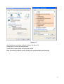
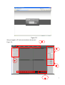
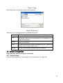
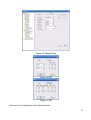
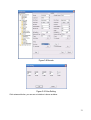
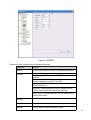
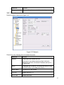
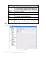
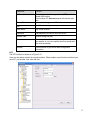
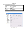
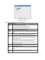
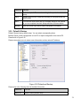
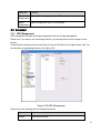
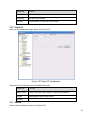
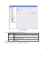
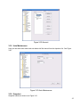
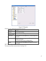
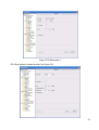
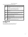
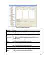
F Series IP Camera Web Operation Manual Version2.1
For F725/F726/F715/F665/F645/F625 series only
1
Table of Contents
1
Network Connection ...................................................................................................................4
2
Main Interface Introduction ........................................................................................................5
3
2.1
Log in ..............................................................................................................................5
2.2
Monitor Channel Menu Tree .......................................................................................8
2.3
System Menu...............................................................................................................10
2.4
Monitor Window Switch..............................................................................................10
2.5
Preview Window Switch.............................................................................................11
2.6
PTZ Control..................................................................................................................11
2.7
Color and More Setup ................................................................................................14
Configure ....................................................................................................................................16
3.1
System Information.....................................................................................................16
3.1.1 Version Information..............................................................................................16
3.1.2 HDD information...................................................................................................16
3.1.3 Log..........................................................................................................................17
3.2
System Configuration .................................................................................................18
3.2.1
3.2.2
3.2.3
3.2.4
3.2.5
3.2.6
3.2.7
3.2.8
3.2.9
General Setup ......................................................................................................18
Encode...................................................................................................................20
Schedule................................................................................................................24
RS232 ....................................................................................................................25
Network..................................................................................................................27
Alarm......................................................................................................................32
Detect.....................................................................................................................34
PTZ.........................................................................................................................37
Default & Backup .................................................................................................38
2
3.3
Advanced .....................................................................................................................39
3.3.1
3.3.2
3.3.3
3.3.4
3.3.5
3.3.6
3.3.7
3.4
HDD Management ...............................................................................................39
Alarm I/O ...............................................................................................................40
Record ...................................................................................................................40
Account..................................................................................................................41
Auto Maintenance ................................................................................................42
Snapshot ...............................................................................................................42
Abnormity ..............................................................................................................43
Additional Function .....................................................................................................45
3.4.1
3.4.2
3.4.3
3.4.4
3.4.5
3.4.6
3.4.7
3.4.8
Configure ...............................................................................................................45
Auto Register ........................................................................................................47
Talk Encode ..........................................................................................................47
IP Filter ..................................................................................................................48
DNS........................................................................................................................48
Wireless Network (For –W series only) ............................................................49
CDMA/GPRS (For –T/E/C series only) ............................................................51
Mobile Configuration (For –T/E/C series only) ................................................53
4
Search.........................................................................................................................................56
5
Alarm...........................................................................................................................................59
6
About...........................................................................................................................................61
7
Log out ........................................................................................................................................62
8
Appendix No-IP DDNS.............................................................................................................63
3
1 Network Connection
This series IPC product support the Web access and management via PC.
Web includes several modules: monitor channel list, record search, alarm setup, system configuration,
PTZ control, monitor window and etc.
IP camera factory default setup:
z IP address: 192.168.1.108.
z User name: admin
z Password: admin
Please follow the steps listed below for network connection.
z Make sure the IPC has connected to the network properly.
z IPC IP address and PC IP address shall be in the same network segment. IPC default IP address is
192.168.1.108. If there is router, please set the corresponding gateway and subnet mask.
z Use order ping ***.***.***.***(* IP camera address) to check connection is OK or not.
4
2 Main Interface Introduction
2.1 Log in
Open IE and input IPC IP address in the address column. For example, if your IP camera is
192.168.1.108, then please input http:// 192.168.1.108 in IE address column. See Figure 2-1
Input your IP
address here.
Figure 2-1
System pops up warning information to ask you whether install webrec.cab control or not. Please click
yes button.
If you can’t download the ActiveX file, please modify your settings as follows. See Figure 2-2.
5
Figure 2-2
After installation, the interface is shown as below. See Figure 2-3.
Please input your user name and password.
Default factory name is admin and password is admin.
Note: For security reasons, please modify your password after you first login.
6
Figure 2-3
②
After you logged in, IPC web main interface is shown as in
Figure 2-4.
③
①
④
⑤
7
⑥
Figure 2-4 Web Main Interface
There are six sections:
z Section 1: Monitor channel menu tree
z Section 2: System menu
z Section 3: PTZ control
z Section 4: Video setup and other setup
z Section 5: Preview window
z Section 6: Monitor window switch
2.2 Monitor Channel Menu Tree
The monitor channel menu tree is shown as in Figure 2-5.
Figure 2-5 Monitor Channel Menu Tree
Please refer to the following sheet for detailed information.
Parameter
Function
Channel 1
Monitor channel 1
Open all /close
all
IPC supports main stream and extra stream.
z Main stream: In normal network width environment, main
stream can record video and audio and realize network
monitor.
z Extra stream: If network width is not sufficient, you can use
extra stream to realize network monitor.
Please note the extra stream resolution shall be less than main
stream resolution.
Click this button to open all video channels.
Once all video channels are open, it becomes close all button.
Start dialogue
You can click this button to enable audio talk.
Audio compression type: G.711a (default), AMR and etc
Local play
Click local play button to select file to play in PC.
8
Refresh
Click this button to refresh monitor channel name.
Please left click one monitor to view real-time video, the monitor window is shown as in Figure 2-6.
1
2
3
4
5 6
78
910
11
Figure 2-6 Real-time Monitor
Please refer to the following sheet for monitor window parameter information.
SN
Parameter
Function
1-4
Display
device
information
z
z
z
z
5
Digital
zoom
6
Change
show
mode
1: IPC IP address.
2: Channel number.
3: Bit stream.
4: Stream decode type.
¾ S1: Overlay.
¾ S2: Off stream.
¾ S3:GD1
¾ H1: Overlay
¾ H2: off stream decoding from the display card.
Click this button and then left drag the mouse in the zone to
zoom in. Right click mouse system restores original status.
Resize or switch to full screen mode.
9
7
Local
record
When you click local record button, the system begins
recording. The recorded file is saved to system folder: \
RecordDownload(default).
You can go to chapter 2.7 to modify the local record save path.
The playback bar is shown as below.
1- Playback process control
2- Play
3- Pause
4- Stop
5- Slow play
6- Fast play
Please note, once you selected window is in real-time monitor
mode, system automatically switches to playback the video by
default.
8
Capture
picture
You can snapshoot important video. All images are memorized
in system folder: \ picture download (default).
9
Audio
Turn on or off audio.(It has no relationship with system audio
setup )
10
Close
video
Close video in current window.
11
Channel
number
Current view channel number.
2.3 System Menu
System menu is shown as in Figure 2-7.
Please refer to chapter 3 Configuration, chapter 4 Search, chapter 5 Alarm, chapter 6 About, chapter 7
Log out for detailed information.
Figure 2-7 System Menu
2.4 Monitor Window Switch
The monitor window switch interface is shown as in Figure 2-8.
10
Figure 2-8 Monitor Window Switch
System supports 1/4/6/8/9/13/16/20/25/36-window real-time preview.
----It is video quality adjustment button. It has relationship with decode via software.
--Fluency button. You can use this function to adjust the priority between real-time and fluency.
2.5 Preview Window Switch
The preview window switch interface is shown as in Figure 2-9.
IPC series products do not support this function.
Figure 2-9 Preview Window Switch
2.6 PTZ Control
Before PTZ operation, please make sure you have properly set PTZ protocol. (Please refer to chapter
3.2.8 PTZ).
Here you can view direction keys, speed, zoom, focus, iris, preset, tour, pan, scan, pattern, aux close,
and PTZ setup button.
Please note: open menu/close menu/up/down/left/right/confirm/cancel buttons are for speed dome only.
z PTZ direction: PTZ supports eight directions: left/right/up/down/upper left/upper right/bottom
left/bottom right.
z Speed: The step 8 speed is faster than step 1.
11
These six buttons are for
speed dome only.
You can click this icon to
display or hide the PTZ
control platform.
Figure 2-10 PTZ Interface
Click PTZ set button, the interface is shown as in Figure 2-11.
12
Figure 2-11 PTZ Setup
Please refer to the following sheet for PTZ setup information.
Parameter
Function
Scan
z
Preset
Tour
Pattern
Assistant
Move the camera to you desired location and then click left limit
button.
z Then move the camera again and then click right limit button to
set a right limit.
Use direction keys to move the camera to your desired location and
then input preset value. Click add button, you have set one preset.
The preset value ranges from 1 to 80. (It may vary due to different
protocols.)
z Input auto tour value and preset value. Click add button, you
have added one preset in the tour.
z Repeat the above procedures you can add more presets in one
tour.
z Or you can click delete button to remove one preset from the
tour.
The tour value ranges from 1 to 8. (It may vary due to different
protocols.)
You can input pattern value and then click start record button to
begin PTZ movement. Please go back to Figure 2-10 to implement
camera operation. Then you can click stop record button in Figure
2-11. Now you have set one pattern.
The assistant items include: BLC, Digital zoom, day/night mode,
camera brightness, flip.
You can select one option and then click start or stop button.
13
Parameter
Function
Matrix
Please select the matrix X, and then input the corresponding monitor
output number, video input channel number, then you can click video
switch button to complete the operation.
2.7 Color and More Setup
Color and other setup interface are shown as in Figure 2-12.
Figure 2-12 Color
Please refer to the following sheet for detailed information.
Parameter
Function
Video
setup
It is to adjust monitor video
brightness.
It is to adjust monitor video contrast
ness.
It is to adjust monitor video
saturation.
It is to adjust monitor video hue.
Note:
z All the operations here
apply to WEB end
only.
z Please go to chapter
3.2.2 System
configuration->Encode
setup->color setting to
adjust corresponding
system items.
Click more button, the interface is shown as in Figure 2-13.
Figure 2-13 Color and More
Please refer to the following sheet for detailed information.
14
Parameter
Function
More
Picture
Path
Click picture path button, system pops up an interface for you
to modify path.
Record
Path
Click record path button, system pops up an interface for you
to modify path.
Reboot
Click this button, system pops up a dialogue box, please click
OK button to reboot device.
15
3 Configure
3.1 System Information
3.1.1 Version Information
Here you can view device hardware feature and software version information. See Figure 3-1.
Figure 3-1 Version Information
3.1.2 HDD information
Here you can view local storage status and network status including, free capacity and total capacity.
See Figure 3-2.
16
Figure 3-2 HDD Information
3.1.3 Log
Here you can view system log. See Figure 3-3.
17
Figure 3-3 Log
Click backup button, the interface is shown as in Figure 3-4.
Figure 3-4 Save Log
Please refer to the following sheet for log parameter information.
Parameter
Function
Type
Log types include: system operation, configuration operation, data
management, alarm event, record operation, user management, log
clear and file operation.
You can select log type from the drop down list and then click search
button to view the list.
Search
Clear
You can click this button to delete all displayed log files. Please note
system does not support clear by type.
Backup
You can click this button to backup log files to current PC.
3.2 System Configuration
Please click save button to save your current setup.
3.2.1 General Setup
Here you can set system time, record length, video format and etc. See Figure 3-5.
18
Figure 3-5 General Setup
Figure 3-6 DST
Figure 3-7 DST
Please refer to the following sheet for detailed information.
19
Parameter
Function
System
Time
Here is for you to modify system time. Please click Save button after
your completed modification
Sync PC
You can click this button to save the system time as your PC current
time.
Data
Format
Here you can select data format from the dropdown list.
Data
Separator
Please select separator such as – or /.
Time
Format
There are two options: 24-H and 12-H.
DST
Here you can set day night save time begin time and end time. See
Figure 3-6 and Figure 3-7.
Language
You can select the language from the dropdown list. Device needs to
reboot to get the modification activated.
HDD Full
There are two options: stop recording or overwrite the previous files
when HDD is full.
Pack
Duration
Here you can select file size. Default setup is 60 minutes.
Device No
When you are using one remote control to manage multiple devices,
you can give a serial numbers to the device.
Please note current series IPC does not support this function.
Video
Standard
This is to display video standard such as PAL.
3.2.2 Encode
Encode interface is shown as in Figure 3-8.
20
Figure 3-8 Encode
Figure 3-9 Color Setting
Click watermark button, you can see an interface is shown as below.
21
Figure 3-10 Watermark
Please refer to the following sheet for detailed information.
Parameter
Function
Channel
Here is for you to select a monitor channel.
Channel Name
Here is to display current channel name. You can modify it .
Compression
H.264
Main Stream
It includes general stream, motion stream and alarm stream. You
can select different encode frame rates form different recorded
events.
System supports active control frame function (ACF). It allows
you to record in different frame rates.
For example, you can use high frame rate to record important
events, record scheduled event in lower frame rate and it allows
you to set different frame rates for motion detection record and
alarm record.
Extra Stream
Select extra stream if you enabled the extension stream to
monitor.
Audio/Video
Main stream: Recorded file only contains video by default. You
need to check the audio box here to enable audio function.
Extra stream: Recorded file only contains video by default. You
need to check the audio box here to enable audio function.
Resolution
The options include: UXGA/1.3M/720/D1/HD1 /CIF/QCIF.
The main stream and extra stream resolution may not be the
same.
Frame Rate
Bit Rate Type
z
F726 series:PAL: 1~12.5f/s,NTSC: 1~15f/s.(Now
system supports 1~12.5f/s).
z
F725/F715/F6X5 series:PAL: 1~25f/s,NTSC: 1~30f/s..
The frame rate may vary due to different resolutions.
There are two options: VBR and CBR.
Please note, you can set video quality in both modes.
22
Parameter
Function
Quality
The value ranges from 1 to 6. The level 6 is the best video
quality.
Bit Rate
z
In CBR, the bit rate here is the max value. In dynamic video,
system needs to low frame rate or video quality to guarantee
the value.
z
The value is null in VBR mode.
z
Please refer to recommend bit rate for the detailed information.
Recommended
Bit
Recommended bit rate value according to the resolution and
frame rate you have set.
I Frame
Here you can set the P frame amount between two I frames. The
value ranges from 1 to 150.
F725/F715/F6X5 series default value is 50 and F726 series
default value is 24.
Recommended value is frame rate *2.
Color Setting
Watermark
Cover area
(privacy mask)
Time Title
Channel Title
Here you can set video brightness, contrast ness, hue, saturation
and gain.
The value ranges from 0 to 100. Default value is 50.See Figure
3-9.
Please note gain value is read only.
Here you can select watermark bit stream, watermark mode and
watermark character. Default character is DigitalCCTV. See
Figure 3-10.
z
Here you can privacy mask the specified video in the monitor
video.
z
System max supports 8 privacy mask zones.
z
You can enable this function so that system overlays time
information in video window.
z
OSD transparent value ranges from 0 to 255. 0 means
complete transparent.
z
You can use the mouse to drag the time tile position.
z
You can enable this function so that system overlays channel
information in video window.
z
OSD transparent value ranges from 0 to 255. 0 means
complete transparent.
z
You can use the mouse to drag the channel tile position.
Save
You can click save button after you complete setup for one item,
or you can complete the whole setups and then click save button.
Refresh
Click this button to get device latest configuration information.
23
3.2.3 Schedule
Here you can set different periods for various days. There are max six periods in one day. See Figure
3-11.
Figure 3-11 Schedule
Figure 3-12 Storage Set
24
Figure 3-13 Schedule Time
Please refer to the following sheet for detailed information.
Parameter
Function
Channel
Please select a channel first.
Pre-record
Please input pre-record value here.
System can record the three to five seconds video before activating
the record operation into the file. (Depends on data size).
Storage
Right now this series product support local storage mode
(record/snapshot).
Setup
z
In Figure 3-11, click set button, you can go to the corresponding
setup interface.
z
Please set schedule period and then select corresponding record
or snapshot type: motion detection/snapshot, and alarm/snapshot.
Right now system does not support schedule/snapshot function,
z
Please select date (Current setup applies to current day by default.
You can draw a circle before the week to apply the setup to the
whole week.)
z
After complete setup, please go back to Figure 3-11 and then click
save to save current time period setup.
Save
You can click save button after you complete setup for one channel,
or you can complete the whole setups and then click save button.
Refresh
Click this button to get device latest configuration information.
3.2.4 RS232
The RS232 interface is shown as in Figure 3-14.
25
Figure 3-14 RS232
Please refer to the following sheet for detailed information.
Parameter
Function
RS232
There is only one option COM 01, corresponding to RS232.
Function
Console is for debug.
Control keyboard: Switch between RS232 and control
keyboard.
Network keyboard: COM control protocol. You can use
network keyboard to control IPC via COM.
Transparent COM: Network user can communicate with
RS232 COM device.
Alarm box: Wireless alarm box protocol. System can use
COM to communicate with the wireless alarm box.
COM_GPS: GPS module protocol. You can connect to it to
realize GPS function.
Data Bit
The value ranges from 5 to 8.
Stop Bit
There are three options: 1/2.
Baud Bit
You can select corresponding baud bit here.
26
Parameter
Function
Parity
There are five options: none/odd /even/mark/space.
3.2.5 Network
Network interface is shown as in Figure 3-15.
Figure 3-15 Network
Please refer to the following sheet for detailed information.
Parameter
Function
Ethernet
Please select the network card first.
If you want to use wireless network, please select port
02(wireless) and then set wireless IP address and etc(For –
W series only)
DHCP
Dynamically get IP address. You can get the device IP from
the DHCP server if you enabled this function.
Device Name
The device ID in the network.
TCP Port
Default value is 37777.
HTTP Port
Default value is 80.
27
Parameter
Function
UDP Port
Default value is 37778.
Max Connection
Network user max amount. The value ranges from 1 to 10.
Network
transmission QoS
You can set the priority between fluency and video quality or
self-adaptive. System can automatically adjust the bit stream
or lower the resolution according to the network bandwidth.
High-Speed
Download
Download the recorded file maximally using the network
bandwidth.
Remote
Host
Multiple
cast
group
z
Set MULCAST address and port.
z
Enable MULCAST function.
z
Current series IPC does not support this function right
now.
PPPOE
z
Input the PPPoE user name and password you get from the
IPS (internet service provider) and enable PPPoE function.
Please save current setup and then reboot the device to
get the setup activated.
z
Device connects to the internet via PPPoE after reboot.
You can get the IP address in the WAN from the IP address
column.
Email
The email interface is shown as in Figure 3-16.
28
Figure 3-16 Email
Please refer to the following sheet for detailed information.
Parameter
Function
SMTP Server
Input server address and then enable this function.
Port
Default value is 25. You can modify it if necessary.
User Name
The sender email account user name.
Password
The sender email account password.
Sender
Sender email address.
Subject
Input email subject here.
Address
Input receiver email address here. Max three addresses.
DDNS
The DDNS interface is shown as in Figure 3-17.
Figure 3-17 DDNS
Please refer to the following sheet for detailed information.
You can refer to the Appendix for NO-IP DDNS setup information.
29
Parameter
Function
Server Type
You can select DDNS protocol from the dropdown list and then
enable DDNS function. The private DDNS protocol means you
use your self-defined private protocol to realize DDNS function.
Server IP
DDNS server IP address
Server Port
DDNS server port.
Domain Name
Your self-defined domain name.
User
The user name you input to log in the server.
Password
The password you input to log in the server.
Interval
z
Device sends out alive signal to the server regularly.
z
You can set interval value between the device and DDNS
server here.
NAS
NAS interface is shown as in Figure 3-18.
Figure 3-18 NAS
Please refer to the following sheet for detailed information.
30
Parameter
Function
NAS enable
Please select network storage protocol (FTP) and then
enable NAS function.
Current series IPC does not support this function right
now.
Server IP
Input remote storage server IP address.
Port
Input Remote storage server port number.
User Name
Log in user account.
Password
The password you need to log in the server.
Remote Path
Remote storage file path.
Save
You can click save button after you complete setup for
one channel, or you can complete the whole setups and
then click save button.
Refresh
Click this button to get device latest configuration
information.
NTP
The NTP interface is shown as in Figure 3-19.
Here you can realize network time synchronization. Please enable current function and then input
server IP, port number, time zone and time.
31
Figure 3-19 NTP
Please refer to the following sheet for detail information.
Parameter
Function
Enable
Enable NTP function or not.
Server IP
Server IP address
Port
Server port.
Time Zone
Device current time zone.
Update Interval
Time update interval value.
3.2.6 Alarm
Alarm setup interface is shown as in Figure 3-20.
Figure 3-20 Alarm Setup
32
Figure 3-21 PTZ Setup
Please refer to the following sheet for detailed information.
Parameter
Function
Event
Type
It includes local alarm/network alarm.
z
Local alarm: Device detects alarm from input port.
z
Network: Device detects alarm from network.
Alarm in
Select corresponding alarm channel (ch01).
Enable
You need to draw a circle here so that system can detect the alarm
signal.
Type
There are two options: normal open and normal close. NO becomes
activated in low voltage, NC becomes activated in high voltage.
Period
z
Alarm record function becomes activated in the specified periods.
z
There are six periods in one day. Please draw a circle to enable
corresponding period.
z
Select date. If you do not select, current setup applies to today only.
You can select all week column to apply to the whole week.
z
Click OK button, system goes back to alarm setup interface, please
click save button to exit.
Anti-dither
System only memorizes one event during the anti-dither period. The
value ranges from 0 to 15s.
Normal
Out
Enable alarm activation function. You need to select alarm output port
so that system can activate corresponding alarm device when alarm
occurs.
Alarm
Latch
System can delay the alarm output for specified time after alarm end
The value ranges from 10 seconds to 300 seconds.
33
Parameter
Function
Record
Channel
System auto activates current channel to record once alarm occurs
(working with alarm activation function). Please note current device
shall be in auto record mode (Chapter 3.2.3 Schedule).
System can delay the record for specified time after alarm ended. Th
value ranges from 10s to 300s.
Record
Latch
Email
Please draw a circle to enable email function. System can send out
email to alert you when alarm occurs and ends.
Tour
z
Display the selected video in local monitor window.
z
This function is not available in current device.
z
Here you can set PTZ movement when alarm occurs. Such as go to
preset x when there is an alarm.
z
The PTZ configuration events include preset, tour, and pattern.
PTZ
activation
Capture
You need to input capture channel number so that system can backu
snapshot file to the SD card or send to the specified email box when
alarm occurs.
Copy
It is a shortcut menu button. You can copy current channel setup to
one or more (all) channels.
Save
You can click save button after you complete setup for one channel,
or you can complete the whole setups and then click save button.
Refresh
Click this button to get device latest configuration information.
3.2.7 Detect
Analysis the video, system enable motion detection alarm when it detects the motion signal reached the
specified sensitivity.
The detection interface is shown as in Figure 3-22.
34
Figure 3-22 Detect
Figure 3-23 Motion Detection Zone Setup
Please refer to the following sheet for detailed information.
Parameter
Function
Event
Type
There are three types: Motion detection/video loss/Camera Masking.
Channel
Select channel name from the dropdown list.
Enable
You need to draw a circle to enable motion detection function.
35
Parameter
Function
Sensitivity
There are six levels. The sixth level has the highest sensitivity.
Region
Period
Anti-dither
Normal
out
z
There are six levels. The sixth level has the highest sensitivity.
z
Region: If you select motion detection type, you can click this button
to set motion detection zone. The interface is shown as in Figure
3-23. There are PAL 22X18/NTSC 22X15 zones. Right click mouse
you can go to full-screen display mode. Do remember clicking OK
button to save your motion detection zone setup.
z
Motion detection function becomes activated in the specified
periods.
z
There are six periods in one day. Please draw a circle to enable
corresponding period.
z
Select date. If you do not select, current setup applies to today only.
You can select all week column to apply to the whole week.
z
Click OK button, system goes back to motion detection interface,
please click save button to exit.
System only memorizes one event during the anti-dither period. The
value ranges from 0s to 15s.
z
There is 1-channel alarm output.
z
Corresponding to motion detection alarm output port.
z
Enable alarm activation function. You need to select alarm output
port so that system can activate corresponding alarm device when
alarm occurs.
Alarm
latch
System can delay the alarm output for specified time after alarm end
The value ranges from 10s to 300s.
Record
channel
System auto activates motion detection channel to record once alarm
occurs (working with motion detection function). Please note you need
to go to Chapter 3.2.3 Schedule to set motion detection record period
and go to chapter 3.3.3 record to set current period as auto record.
Record
latch
System can delay the record for specified time after alarm ended. The
value ranges from 10s to 300s.
Email
If you enabled this function, System can send out email to alert you
when alarm occurs and ends.
PTZ
Activation
z
Capture
You need to input capture channel number so that system can backup
motion detection snapshot file.
Save
You can click save button after you complete setup for one channel,
or you can complete the whole setups and then click save button.
Here you can set PTZ movement when alarm occurs. Such as go to
preset x when there is an alarm.
36
Parameter
Function
Refresh
Click this button to get device latest configuration information.
3.2.8 PTZ
PTZ interface is shown as in Figure 3-24
Please note, before operation please make sure you have set speed dome address and the IPC and
speed dome connection is OK.
Figure 3-24 PTZ
Please refer to the following sheet for detailed information.
Parameter
Function
Channel
You can select monitor channel from the dropdown list. .
Protocol
Select the corresponding dome protocol.(such as PELCOD)
Address
Set corresponding dome address. Default value is 1. Please note your
setup here shall comply with your dome address; otherwise you can
not control the speed dome.
Select the dome baud rate. Default setup is 9600.
Baud
Rate
Data Bit
Default setup is 8. Please set according to the speed dome dial switch
setup.
37
Parameter
Function
Stop bit
Default setup is 1. Please set according to the speed dome dial switch
setup.
Parity
Default setup is none. Please set according to the speed dome dial
switch setup.
Save
You can click save button after you complete setup for one channel,
or you can complete the whole setups and then click save button.
Refresh
Click this button to get device latest configuration information.
3.2.9 Default & Backup
Default: Restore factory default setup. You can select corresponding items.
Backup: Export current configuration to local PC or import configuration from current PC.
Please refer to Figure 3-25.
Please note system can not restore some information such as network IP address.
Figure 3-25 Default and Backup
Please refer to the following sheet for detailed information.
Parameter
Function
Select All
Restore factory default setup.
38
Parameter
Function
Export
Configuration
Export system configuration to local PC.
Import
Configuration
Import configuration from PC to the system.
3.3 Advanced
3.3.1 HDD Management
HDD management includes net storage management and local storage management.
Please note, if you want to use local storage function, your storage device need to support current
function.
Please select the storage device first and then you can see the items on your right become valid. You
can check the corresponding item here. See Figure 3-26.
Figure 3-26 HDD Management
Please refer to the following sheet for detailed information.
Parameter
Function
Format
Clear data in the disk.
39
Parameter
Function
Read/write
Set current disk as read/write
Read only
Set current disk as read.
Execute
Click this button to save disk current status.
3.3.2 Alarm I/O
Here you can search alarm output status. See Figure 3-27.
Figure 3-27 Alarm I/O Configuration
Please refer to the following sheet for detailed information.
Parameter
Function
Alarm output
There is only one output channel. Please click the button 1.
Trigger
Enable/disable alarm output device.
Refresh
Search alarm output status.
3.3.3 Record
Record control interface is shown as in Figure 3-28.
40
Figure 3-28 Record
Please refer to the following sheet for detailed information.
Parameter
Function
Auto
System enables auto record function as you set in record schedule
setup.
Enable corresponding channel to record no matter what period
applied in the record setup.
Stop current channel record no matter what period applied in the
record setup.
Manual
Stop
3.3.4 Account
Here you can add, remove user or modify password. See Figure 3-29.
41
Figure 3-29 Account
3.3.5 Auto Maintenance
Here you can select auto reboot and auto delete old files interval from the dropdown list. See Figure
3-30.
Figure 3-30 Auto Maintenance
3.3.6 Snapshot
Snapshot interface is shown as in Figure 3-31.
42
Figure 3-31 Snapshot
Please refer to the following sheet for detailed information.
Parameter
Function
Channel
It is the monitor channel.
Snapshot mode
There are two modes: Timing and activation.
Frame rate
You can select from the dropdown list. The value ranges from
1f/s to 8f/s.
Resolution
You can select from the dropdown list. The options include:
UXGA/D1 /CIF/QVGA.
The resolution may vary due to different series.
Please note F726 series supports UXGA/D1 only.
You can select from the dropdown list. Here is for you to set
video quality.
Quality
3.3.7 Abnormity
The abnormity interface is shown as below. See Figure 3-32.
43
Figure 3-32 Abnormity-1
IPC offline interface is shown as below. See Figure 3-33.
44
Figure 3-33 Abnormity-2
Please refer to the following sheet for detailed information.
Parameter
Function
Event
Type
z
The abnormal events include: no disk, no space, disk error, net error,
IP conflict.
z
Threshold: You can set the minimum percentage value here. The
device can alarm when capacity is not sufficient.
z
You need to draw a circle to enable this function.
Normal
Out
The corresponding alarm output channel when alarm occurs, There is
one channel.
Record
channel
System auto activates channel to record once alarm occurs (For offline
type only. See Figure 3-33. ). Please note you need to go to chapter
3.3.3 record to set current period as auto record.
Record
latch
System can delay the record for specified time after alarm ended. The
value ranges from 10s to 300s.
Latch
The alarm output can delay for the specified time after alarm stops. The
value ranges from 10s to 300s.
Send
email
If you enable this function, system can send out email to alarm the
specified user.
This function is invalid when network error occurs.
3.4 Additional Function
3.4.1 Configure
Here you can set camera property parameter. See Figure 3-34.
The following interface may vary due to different IPC series.
45
Figure 3-34 Configure
Please refer to the following sheet for detail information.
Parameter
Function
Channel
Monitor channel 1
Exposure Mode
There are two modes: Auto exposure (AE) and Manual
exposure (ME).
There are some ME time ranges from 1/50 to 1/10000.
Day/Night Mode
IPC day night mode switch.
There are three options: color-off/color-on/auto.
BLC
Backlight compensation level
There are four levels: Off/weak/middle/strong.
White Balance
White balance is auto by default. The setup here is read-only.
Auto Iris
You can enable or disable the auto iris.
Please make sure your iris supports this function.
Scene Mode
You can select the corresponding mode for various
environments so that you can get the best video effect.
The option includes:
disable/auto/sunny/cloudy/home/office/night.
Signal Standard
Video input mode: internal input.
46
Mirror
It is to switch video left and right limit.
Please note current series IPC does not support this function.
Flip
It is to switch video up and bottom limit.
Please note current series IPC does not support this function.
3.4.2 Auto Register
Auto register interface is shown as below. See Figure 3-35.
Figure 3-35 Auto Register
Please refer to the following sheet for detailed information.
Parameter
Function
Enable
Enable auto register function.
No.
Device management server number.
IP
Device management server IP address.
Port
Server port number.
Device ID
Device ID in the device management server.
3.4.3 Talk Encode
47
Here you can set AMR audio compression bit rate. It ranges from AMR59~AMR475.See Figure 3-36.
Figure 3-36 Talk Encode
3.4.4 IP Filter
You can enable IP filter function so that some specified IP user can access the IPC. See Figure 3-37.
Figure 3-37 IP Filter
3.4.5 DNS
Here you can set server or local operator DNS address. See Figure 3-38.
48
This function is useful when you input domain name in some item. Otherwise system can not parse the
domain name.
Figure 3-38 DNS
3.4.6 Wireless Network (For –W series only)
After you connected to the WiFi module, you can use WEB to set wireless router setup.
Please follow the steps listed below:
z Click SSID search button to search wireless router available. See Figure 3-39.
z Click enable button.
z Double click the wireless router ID available to implement setup. Wireless network modes, WEP,
encryption type are automatically set in accordance with the wireless router.
z If the wireless router adopts WEP encryption, you need to set encryption information manually. See
Figure 3-40. Please input encryption mode, password mode and corresponding password and
verification mode. Click save button to save current setup. Click refresh button to get latest
configuration.
49
Figure 3-39 Search wireless router
Figure 3-40 wireless router setup
50
Please refer to the following sheet for detailed information.
Parameter
Function
SSID search
Click this button to search the wireless router available.
Enable
Enable wireless configuration function.
SSID ID
Corresponding wireless router ID
Mode
Wireless network mode. It includes auto, Adhoc and Infrastructure.
Enable WEP encryption or not.
Encryption
If you select to disable encryption, you can not see the following
items (WEP, Key Type, and ID).
WEP
Select WEP encryption mode. It includes WEP64 bit and
WEP128bit.
Key Type
Select password mode. It includes two options: ASCII and hex.
ID
The password to log in the wireless router. Max supports 4 groups.
Save
Click this button to save current setup.
Refresh
Click this button to get device latest configuration.
3.4.7 CDMA/GPRS (For –T/E/C series only)
The CDMA/GPRS interface is shown as below. See Figure 3-41.
Figure 3-41 CDMA/GPRS
51
Figure 3-42 Schedule Setup
Please refer to the following sheet for detail information.
Parameter
Function
Wireless type
You can select from the dropdown list.
Enable
Please check the box to enable the selected function.
APN
Please input the connection name here.
Dial/SMS activate state
There are two types for the device to connect to the 3G. It includes
the dial-up and sms.
Dial-up number
Please input 3G network dialup number here.
Username
The user name for you to login the 3G network.
Password
The password for you to login the 3G network.
Keep alive time
You can set dialup duration. Default value is 30s.
Period
Click set button, the interface is shown as in Figure 3-42.
You can set the period to connect to the 3G network. System only
enables wireless network dialup function during the specified period.
There are max six periods in one day.
Wireless
network
Login
status
You can see device has registered to the 3G network or not.
52
status
Wireless
signal
IP address
After the Radius server verification, you can see the device IP
address the DHCP server allocated to.
Subnet
mask
After the Radius server verification, you can see the device subnet
mask the DHCP server allocated to.
Gateway
After the Radius server verification, you can see the device gateway
the DHCP server allocated to.
CDMA_1X
signal
You can view current 3G network signal.
EVDO
signal
z
After the device connected to the EVDO module,you can view
CDMA_1x network signal.
z
After the device connected to the W-CDMA or TD module,you can
view the EDGE network signal.
You can view current 3G network signal.
z
After the device connected to the EVDO module,you can view
EVDO signal.
z
After the device connected to the W-CDMA module,you can view
W_CDMA network signal here.
z
After the device connected to TD module,you can view TDSCDMA network signal here.
Save
Click this button to save current setup.
Refresh
Click this button to get device latest configuration.
3.4.8 Mobile Configuration (For –T/E/C series only)
Mobile configuration interface is shown as in Figure 3-43.
53
Figure 3-43 Mobile Configuration
Please refer to the following sheet for detail information.
Parameter
Function
Send event
message
Device can send the event message (alarm information, motion detection
and etc) to the mobile user. You can check the box to enable the function.
Receiver
You can input one or more mobile number(s) here to receive the
message.
SMS activate
The mobile user can send out message to activate the device to connect
to the 3G network.
You need to check the box to enable current function.
Sender
You can input several senders’ mobile number here.
Dial activate
The mobile user can give a call to activate the device to connect to the 3G
network.
You need to check the box to enable current function.
Caller
You can input several senders’ mobile number here.
Add
Click it to add the corresponding mobile phone user.
Delete
Click it to remove the corresponding mobile phone user.
54
Message type
There are two types: SMS and MMS.
Right now system supports SMS only.
Title
You can input message subject here.
Event message
save
System can save the message receiver number so that device can send
out alarm (motion detect) message to the specified mobile phone(s).
SMS save
System can save the mobile phone number which can send out the
message to activate the device.
Before the operation, please make sure you device can connect to the 3G
network and you have enabled the 3G function.
When the specified mobile number sends out the message “on” to the
device, the device begins 3G dial up and then connect to the 3G network.
When the specified mobile number sends out the message “off” to the
device, the device disconnects the network and then becomes offline.
Dial save
System can save the mobile phone number which can dial the device to
enable it to connect to the 3G network.
Before the operation, please make sure you device can connect to the 3G
network and you have enabled the 3G function.
When the specified mobile phone number gives a call to the device, the
user can hear device prompt: The user is busy now. Then the device
begins dial up and connects to the 3G network.
Refresh
Click this button to get device latest configuration.
55
4 Search
Click search button, you can see an interface is shown as in Figure 4-1.
Please select record playback mode, and then select start time, end time and channel. Then please
click search button, you can see the corresponding files in the list.
Select the file(s) you want to download and then click download button, system pops up a dialogue box
shown as in Figure 4-2 , then you can specify file name and path to download the file(s) to your local pc.
Click Ok to complete the download procedure.
Figure 4-1 Search Main Interface
56
Figure 4-2 Save as
Figure 4-3 Watermark
Please refer to the following sheet for detailed information.
Type
Parameter Function
Type
Record
Search general record, alarm record and motion
detection record.
Alarm
Search alarm record.
Motion
Search motion detection record.
Detection
Local
Search local record.
Picture
Search snapshot file.
Card
This function is not available in current device.
Item
Start time
Set the file start time.
End time
Set the file end time.
Channel
Select the channel from the dropdown list.
57
Type
Operation
Parameter
Search
Playback
Download
type
Download
Open local
record
Watermark
Function
Click this button you can view the recorded file matched
your requirements.
Select the file first and then click playback button to view
the video.
Download by file: Select the file(s) and then click
download button.
Download by time: Download the recorded file(s) within
your specified period.
Select the file you need (multiple choices) and then click
download button, you can see system pops up a
dialogue box.
Input the downloaded file name, specify the path and
then click OK button. You can see system begins
download and the download becomes stop button. There
is a progress bar for your reference.
Select local record to play.
Please note, you need to go to chapter 3.2.2 Encode
to enable watermark function first.
Click watermark button, system pops up a dialogue box
shown as in Figure 4-3. Default watermark character is
DigitalCCTV.
Click local file you can select the recorded file. Then you
can click verify button to check file is original or not.
System supports playback one file in several monitor
channels.
Multiplechannel
playback
During the playback process, you can see there are control buttons such as play, pause, stop. slow play
and fast play in the play process bar. You can view current playback file channel name, time and data
statistics.
58
5 Alarm
Click alarm function, you can see an interface is shown as in Figure 5-1.
Here you can set device alarm type and alarm sound setup.
Figure 5-1 Alarm
Please refer to the following sheet for detailed information.
Type
Parameter
Function
Alarm
Video loss
System alarms when video loss occurs.
Type
Motion detection System alarms when motion detection alarm
occurs,
Disk full
System alarms when disk is full.
Disk error
System alarms when disk error occurs.
Camera
System alarms when camera is viciously masking.
masking
Encode alarm
System alarms when encode module alarms.
External alarm
Alarm input device sends out alarm.
Operation Listening alarm
System notifies web when alarm occurs (you select
from the above event type), and then web can
notify user.
Video
When alarm occurs, system auto enables video
monitor. This function only applies to video
detection alarm (motion detection, video loss and
camera masking).
This function is invalid in external alarm mode.
59
Type
Parameter
Prompt
Sound pop up
Path
Function
Automatically pops up alarm dialogue box.
System sends out alarm sound when alarm occurs.
You can specify as you wish.
Here you can specify alarm sound file.
60
6 About
Click about button, you can view current web client information. See Figure 6-1.
Figure 6-1
61
7 Log out
Click log out button, system goes back to log in interface. See Figure 7-1.
Figure 7-1
62
8 Appendix No-IP DDNS
Please double click DDNS to go to the configuration interface. You can see an interface is shown as in
Figure 8-1.
Figure 8-1
y
DDNS Type: You can select from the dropdown list. There are five options: No-IP, DynDNS, CN99,
Private and Oray.
y
Server IP: You can use ping command to get server’s IP
y
Port: input server port here.
y
Domain Name: Get the domain name you get from your DDNS service provider.
y
User: Get the user name you get from your DDNS service provider.
y
Password: Enter corresponding password.
Highlight the icon
in front of Enable to enable the DDNS server configuration.
It’s a system of dynamic DNS service. If you do not have a Static IP address on the Internet, you need
to have a dynamic IP. It is to say your IP address changes after a certain period of time.
You can follow the steps listed below to display image on your device even your IP is dynamic.
63
You need to use a DDNS service and create a domain name that is not necessarily direct use the IP
address.
After completed configuration in the device DDNS service can constantly inform the latest device’s
connection IP, and modify its IP on the table of data from the server. Then we have a constant domain
name in the Web browser, along with the HTTP port, send a request to identify the car IP of the domain
name typed. The server will direct the domain name to the IP connection, thus allowing access to the
device which does not have a fixed IP in the network.
Note: It is important to note that to gain access to the device in a local network, it is necessary to
achieve the redirect the port of your modem or router to your device.
To receive domain name in the No-IP DDNS service, please follow the steps listed below.
1.
Please visit www.no-ip.com; the page of No-IP appears as below. See Figure 8-2.
Figure 8-2
2.
Left click mouse on the “Create Account” button, account Information interface is shown as in Figure 8-3.
64
Figure 8-3
3.
Fill in the requested fields and click I Accept button. Then you can get an email containing username and password.
You can use this account to access the service.
4.
Open the e-mail sent by trusted rmação No-IP and double-click the link that is below the phrase "To activate your
account please click the following URL:" in the body of the email. See Figure 8-4.
Figure 8-4
65
5.
Now you can see an interface is shown as in Figure 8-5. You have successfully created an account.
Figure 8-5
6.
In Figure 8-5, click to sign and enter the email address and password you get earlier. Click “login” to sign up, you can
see the welcome interface and configuration option of account. See Figure 8-6. You can highlight manage host item.
Figure 8-6
7.
The Manage Hosts interface is shown as in Figure 8-7. Click the Add Host button you can access the creation of a
domain name.
66
Figure 8-7
8.
In Figure 8-8, input corresponding host name in the filed. You can use this name to access device from an external
network. In the field to the right of the name, select the desired area. This is your domain name for access to the
device. Click “Create Host” button at the bottom of the page.
Figure 8-8
9.
Now you can see an interface is shown as in Figure 8-9. Here you can view domain name and the computer's
current IP setup. If you already have a domain name equal to gurado trusted, you must define another name for the
host.
67
Figure 8-9
10. Now you need to define the definition of the server's IP in IP-device able to access this service DDNS. To get DDNS
service, you need to have a computer connected to the Internet on the same network with device. Then please type
the command dynupdate. no ping-ip.com at the command prompt, Windows ®. The server's IP will be displayed on
the screen. See Figure 8-10. Your device can use this IP to find the No-IP server.
Figure 8-10
11. Please go to the device and access the MAIN MENU> SETTING> NETWORK> DDNS. Input server IP you get in the
above step. Select the DDNS Type as No-IP DDNS and highlight the icon
in front of Enable to enable the DDNS
function. Now fill the fields as described below, and click OK to save current setup.
• Server IP: Enter the IP noted in step 10.
• Port: Enter the port 80.
68
• Domain Name: Enter the domain name created in step 8.
• User: Enter your username (email address) created in step 3.
• Password: Enter the password created in step 3.
The figure Configuration file of No-IP is shown as in Figure 8-11.
Figure 8-11
12. Now you have completed device setup. Open Internet Explorer ® in another foreign network with Internet access,
unlike the network where the device is connected to, you need to follow the steps listed below:
1. Enter the address into your browser: http://nome the field created in step 8. For example: http://vd16s480st.noip.biz
2. If the device HTTP port is 80, just type the domain name. Otherwise, enter in the browser address as: http://nome
the field created in Step 8: port number of HTTP. For example:
http://vd16s480st.no-ip.biz:9090
3. Press Enter. The system will ask install application webrec.cab control or not. Please click Yes to perform a
successful connection.
4. If the page does not appear on the computer screen, you need to lower your system safety setup. From Tools>
Internet Options> Security, select Internet and then click Custom Level, you can enable ActiveX controls. See Figure
8-12 . Then open your browser and re-enter the domain name of the device.
69
Figure 8-12
Note:
Slight difference may be found in user interface.
All the designs and software here are subject to change without prior written notice.
Please visit our website for more information.
70