1
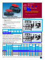
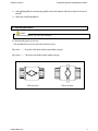
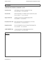
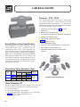
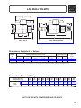
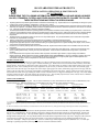
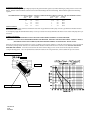
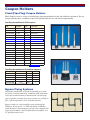
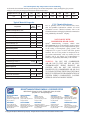
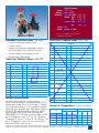
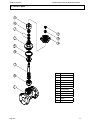
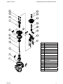
PROMINENT PRE-ENGINEERED SYSTEM P/N: 7746434-0-701 2 COUPON RACK 1” PVC OPTION 2 WITH ROTOTMETER PIPING COMPONENTS ASAHI PVC/EPDM OMNI BALL VALVES SPEARS PVC/EPDM LAB BALL VALVES HAYWARD CLEAR PVC/VITON Y-STRAINER METAL SAMPLES PVC/NYLON COUPN HOLDER SPEARS SCH.80 PVC PIPING & FITTINGS ASAHI PVC/EPDM GLOBE VALVE BLUE-WHITE ACRYLIC 10 GPM ROTOMETER Sizes: Models: Bodies: Seats: Seals: Specifications 3/8" – 3" Socket and Threaded PVC, CPVC PTFE backed with EPDM EPDM Sizes 3/8" - 3" PVC/EPDM Models available with NSF-61 Certification Omni® is a Trademark of Asahi/America, Inc. Omni® Ball Valve Parts List (Sizes 3/8"– 3") Blocks in two directions Rugged structure Unibody construction Compact, low profile, short face-to-face dimensions PTFE seat backed by EPDM for low stem torque Rated for full vacuum service SOCKET END A 5 30˚ F 120˚ F 121˚ F 140˚ F 141˚ F 175˚ F 176˚ F 195˚ F 3/8-2 13-50 80 150 150 150 150 120 120 90 90 60 60 SOCKET END A 5 Sample Specification ® H 8 NOMINAL SIZE INCHES 3/8 ød 7 6 2 1 3 L Weight (LBS.) Cv Values THREADED NOMINAL SIZE mm Cv 13 0.22 3/8 13 7.7 15 0.26 1/2 13 14 20 0.55 3/4 20 29 25 0.88 1 25 47 0.94 5.00 1 1/4-11 1/2 NPT 0.87 5.00 1.22 3.74 2.13 2.76 2.76 1 1/4 32 1.09 5.98 1 1/2-11 1/2 NPT 0.98 5.94 1.38 4.33 2.50 2.99 2.99 1 1/2 40 50 1.16 6.93 2-11 1/2 NPT 1.10 6.97 1.77 4.33 3.01 3.31 3.31 2 80 1.87 9.29 3-8 NPT 1.17 9.29 2.70 7.87 4.25 4.88 4.88 3 1.21 1 1/4 30 72 1.32 1 1/2 40 1/2-14 NPT 0.59 3.82 0.59 2.76 1.22 1.38 1.73 3/4 20 1.058 1.046 0.72 4.02 3/4-14 NPT 1 25 1.325 1.310 0.87 4.49 1-11 1/2 NPT 0.67 4.06 0.79 3.15 1.46 2.17 2.17 3/4 0.79 4.45 0.98 3.15 1.77 2.36 2.36 1 50 2.387 2.369 INCHES 1/2 15 0.848 0.836 0.69 3.82 80 3.516 3.492 NOMINAL SIZE L d A D D1 h l 0.59 3.35 0.51 2.36 1.22 1.38 1.65 3/8 d1 INCHES 1/2 2 SOCKET THR'D 3/8-18 NPT l d1 d2 L 13 0.687 0.671 0.59 3.35 3 1a mm mm 1 1/2 40 1.912 1.894 l l ASTM SCH 40 1 1/4 32 1.670 1.655 øD1 ød1 øD ød2 ød L Dimensions (Sizes 3/8" – 3") SOCKET THREADED END 4 All OMNI ball valves size 3/8"- 3" shall be of one-piece compact design non-union type. All O-rings shall be EPDM or FKM with PTFE seats. Seats must have elastomeric backing cushions of the same material as the valve seals. PVC conforming to ASTM D1784 Cell Classification 12454A, and CPVC conforming to ASTM D1784 Cell Classification 23567-A. Valve shall be rated 150 psi at 70ºF, as manufactured by Asahi-America, Inc. øD *Used for CPVC body, threaded end, 1/2”–1” øD1 30˚ F 120˚ F 1 3 L øD mm 1a ød1 INCHES l l 7 6 2 CPVC øD1 ød L Pressure vs. Temperature (PSI, WATER, NON-SHOCK) 3 øD1 ød Options PVC ød1 H 8 • FKM backing cushions and O-ring • Electrically actuated NOMINAL SIZE THREADED END 4 ød1 øD • • • • • • ød2 Standard Features (Sizes 3/8" – 3") 140 2.20 2 50 185 6.61 3 80 410 35 Green Street, P.O. Box 653, Malden, MA 02148 • Tel: 800-343-3618 • 781-321-5409 • Fax: 800-426-7058 • E-mail: [email protected] Register at our interactive web site for on line ordering, product availability, order tracking, and many useful features: www.asahi-america.com 15 ASAHI AV VALVES Installation,Operation and Maintenance Manual Serial No. H – V030E – 2 Compact Ball Valves "OMNI Ball Valves" User ’s Manual Contents 1. General operating instructions (Page) 1 2. General care & storage instructions 1 3. Names of parts 2 4. Comparison between operating temperature and pressure 2 5. Installation procedure 3 6. Operating procedure 4 7. Inspection items 5 8. Troubleshooting 5 9. Residual and Waste Materials Disposal 5 10. Inquires 5 ASAHI AV VALVES Compact Ball Valves 0 ASAHI AV VALVES Installation,Operation and Maintenance Manual (1) General operating instructions 䂾 Operate the valve within the pressure Vs temperature range. 䋨The valve can be damaged by operating beyond the allowable range.䋩 䂾 Select a valve material that is compatible with the media, refer to “CHEMICAL RESISTANCE ON ASAHI AV VALVE”. 䋨Some chemicals may damage incompatible valve materials.䋩 䂾 Do not use the valve to fluid containing slurry. (The valve will not operate properly.) 䂾 Do not use the valve on condition that fluid has crystallized. (The valve will not operate properly.) 䂾 Do not step on the valve or apply excessive weight on valve. (It can be damaged.) 䂾 Do not exert excessive force in closing the valve. 䂾 Make sure to consult a waste treatment dealer to dispose of the valves. (Poisonous gas is generated when the valve is burned improperly.) 䂾 Allow sufficient space for maintenance and inspection. 䂾 Keep the valve away from excessive heat or fire. (It can be deformed, or destroyed.) 䂾 The valve is not designed to bear any kind of external load. Never stand on or place anything heavy on the valve at anytime. 䂾 Certain liquid such as H2O2, NaClO, etc may be prone to vaporization which may cause irregular pressure increases, which may destroy the valve. (2) General instructions for transportation, unpacking and storage 䂾 Keep the valve packed in the carton or box as delivered until installation. 䂾 Keep the valve away from any coal tar, creosote (antiseptic for wood), termite insecticide, vermicides, and paint. 䋨This could cause swelling damage the valve.䋩 䂾 Do not impact or drop the valve. (It can be damaged.) 䂾 Avoid scratching the valve with any sharp object. Compact Ball Valves 1 ASAHI AV VALVES Installation,Operation and Maintenance Manual (3) Names or parts Handwheel Body End connector (4) Comparison between working temperature and pressure Caution Do not operate the valve beyond the range of working temperature and pressure. (The valve can be damaged.) Compact Ball Valves 2 ASAHI AV VALVES Installation,Operation and Maintenance Manual (5) Installation procedure Threaded end Necessary item 䃂 Sealing tape (A non- sealing tape can cause leakage.) 䃂 Strap wrench (Don’t use a pipe wrench.) 䃂 Spanner wrench Caution Make sure that the threaded connections are plastic x plastic. (Metallic thread can be damaged) Procedure 1) Wind a sealing tape around the external thread of the joint, leaving the end (about 3mm) free. 2) Tighten the external thread of the joint and the end connector lightly by hand. 3) Using a spanner and a strap wrench, screw in the end connector by turning 180䉙-360䉙 carefully without damaging it. Caution Avoid excessive tightening. (The valve can be damaged.) Socket end Necessary item 䃂 Adhesive for rigid polyvinyl chloride pipe (PVC) 䃂 Adhesive for heat – resistant polyvinyl chloride pipe (C – PVC) Caution Don’t install a socket type valve where the atmospheric temperature is 5㫦or lower. (The valve can be damaged.) Procedure 1) Clean the hub part of the end connector by wiping with waste cloth. 2) Apply adhesive evenly to the hub part of the end connector and the pipe spigot. Caution Don’t apply more adhesive than necessary. (The valve can be destroyed due to solvent cracking.) Adhesive quantity (guideline) 13mm 15mm Nom. Size (3/8”) (1/2”) Quantity(g) 0.8 1.0 Compact Ball Valves 20mm (3/4”) 1.3 25mm (1”) 2.0 30mm (1 1/4”) 2.4 40mm (1 1/2”) 3.5 50mm (2”) 4.8 80mm (3”) 9.0 3 ASAHI AV VALVES Installation,Operation and Maintenance Manual 3) After applying adhesive, insert the pipe quickly to the end connector and leave it alone for at least 60 seconds. 4) Wipe away overflowing adhesive. (6) Operating procedure Caution Avoid excessive tightening. (The valve can be damaged.) 䂾 Turn the handle gently to open or close. (Turn the handle clockwise to close and counter clockwise to open.) Fully closed 㵺㵺 The position of the handle should be perpendicular to the pipe. Fully opened 㵺㵺 The position of the handle should be parallel to the pipe. Full open state Compact Ball Valves Full closed state 4 ASAHI AV VALVES Installation,Operation and Maintenance Manual (7) Inspection items 䂾Inspect the following items. (1) (2) (3) Existence of scratches, cracks, deformation, and discoloring. Existence of leakage from the valve to the outside. Existence of leakage when the valve is opened fully at right or left. (8) Trouble shooting The valve is not able disassemble. Please replace the valve to new complete another valve, if the trouble may be occurred in parts of the valve. (9) Discarding remaining or waste materials Caution In discarding remaining or waste materials, be sure to ask a waste service company. (Poisonous gas is generated.) Compact Ball Valves 5 ASAHI AV VALVES Installation,Operation and Maintenance Manual (10) Inquires ASAHI ORGANIC CHEMICALS INDUSTRY CO., LTD. Nobeoka Head Office : 2-5955, Nakanose- Cho, Nobeoka –City, Miyazaki- Pref. , Japan. Tel : (81) 982-35-0880 Tokyo Head Office Fax : (81) 982-35-9350 : (Furukawachiyoda Bldg.) 15-9, Uchikanda 2- Chome, Chiyoda-Ku, Tokyo, Japan. Tel : (81) 3-3254-8177 Singapore Branch Office Fax : (81) 3-3254-3474 : 16 Raffles Quay, #40-03 Hong Leong Building, Singapore 048581. Tel : (65) 220-4022 Fax : (65) 324-6151 Europe Representative Office : Kaiser-Friedrich-Promenade 61 D-61348 Bad Homburg v. d. H. Germany. Tel : (49) 6172-9175-0 Shanghai Branch Office : Room 1301-P Shanghai Kerry Center, 1515 Nanjing Xi Road, Shanghai China Tel : (21) 5298-6900 ASAHI /AMERICA Inc. Fax : (49) 6172-9175-25 Fax : (21) 5298-6556 :35 Green Street P.O.Box 653 , Malden, Massachusetts 02148 U.S.A. Tel : (1) 781-321-5409 Fax : (1) 781-321-4421 Distributor Compact Ball Valves 6 ASAHI AV VALVES Installation,Operation and Maintenance Manual Compact Ball Valves ASAHI AV VALVES Information in this manual is subject to change without notice. Compact Ball Valves 2003. 3 7 LAB BALL VALVES Features – PVC, CPVC This versatile quarter-turn shutoff valve is ideally suited for a variety of laboratory, system monitoring and OEM applications. Available in IPS sizes 1/4" - 3/8" with socket or threaded end connectors, plus 1/4" threaded Valve & Adapter Kit to provide multiple connection options. • Chemical & Corrosion Resistant PVC or CPVC Construction • Maintenance-Free Sealed Unit • Individual Valve or Multi-functional Valve & Adapter Kit • Schedule 80 Full-Bore Design • High Impact Polypropylene Handle • EPDM or Viton® O-rings Sample Engineering Specification All thermoplastic valves shall be sealed unit Lab type constructed from PVC Type I, ASTM D 1784 Cell Classification 12454 or CPVC Type IV, ASTM D 1784 Cell Classification 23447. All O-rings shall be EPDM or Viton®. All valves shall have double stop Polypropylene handle. All 1/4" valves shall have optional field installable male thread and tubing end connector adapters. All valves shall be certified by NSF International for use in potable water service. All valves shall be pressure rated at 150 psi for water at 73°F, as manufactured by Spears® Manufacturing Company. • PTFE Floating Seat Design • Sizes 1/4" - 3/8" Pressure Rated to 150 psi @ 73°F • NSF Certified for Potable Water use • Assembled with Silicone-Free, Water Soluble Lubricant Quick-View Valve Selection Chart Valve Size 1/4 3/8 PVC Part Number1 O-ring Material Socket EPDM Viton® EPDM Viton® 1522-002 1532-002 1522-003 1532-003 Threaded Threaded with Kit 1521-002 1529-002 1531-002 1539-002 1521-003 N/A 1531-003 N/A Pressure Rating 150 psi Non-Shock Water @ 73°F 1: For CPVC Valves, add the letter “C” to part number listed (e.g., 1521-002C) Valve & Adapter Kit Kit allows multiple connection options. Adapters use O-ring seals for easy connection to threaded valve. Complete Kit includes: 1 – 1/4" Threaded Valve 2 – 1/4" O-ring Sealed Mpt x Mipt Adapters 2 – 1/4" O-ring Sealed Mpt x Barb Adapters (for 3/8" I.D. tubing) 2 – EPDM or Viton® O-rings (AS568A-013 size) 1 – End Connector Wrench 48 LAB VALVE WITH ADAPTER KIT LAB BALL VALVES Valve with Adapter Kit Basic Valve Dimensions, Weights & Cv Values Dimension Reference (inches, ± 1/16) Approx. Wt. (Lbs.) Nominal Size A B1 C D E PVC CPVC Cv 2 Values 1/4 1/4 w/Kit 3/8 1-1/16 1-1/16 1-5/16 15/16 2-7/16 1 2-1/8 3-7/8 2-3/16 1-1/16 1-1/16 1-1/4 1-3/4 1-3/4 2 .10 .14 .12 .11 .15 .13 10 6 24 1: Valve Lay Length 2: Gallons per minute at 1 psi pressure drop. Values calculated from valve laying length, based on derivative of Hazen-Williams equation with roughness factor of C=150. Temperature Pressure Rating System Operating Temperature °F (°C) Valve Pressure Rating psi (MPa) PVC CPVC 73 (23) 100 (38) 110 (43) 120 (49) 130 (54) 140 (60) 150 (66 160 (71) 170 (77) 180 (82) 190 (88) 150 (1.03) 150 (1.03) 124 (.85) 140 (.97) 100 (.69) 130 (.90) 75 (.52) 120 (.83) -0(-0-) 110 (.76) -0(-0-) 100 (.69) -0(-0-) 90 (.62) -0(-0-) 80 (.55) -0(-0-) 70 (.48) -0(-0-) 60 (.41) -0(-0-) -0(-0-) NOT FOR USE WITH COMPRESSED AIR OR GASES 49 HAYWARD Flow Control Systems ® Y Strainers - Clear PVC 1/2˝ to 2˝ Clear PVC Construction See how much dirt and debris have been trapped by the strainer screen in the Hayward Clear PVC Y Strainer. The translucent PVC body shows the strainer screen in operation. This helps determine when it needs cleaning based on a visual check of the amount of debris retained by the screen. These Y strainers are available in pipeline sizes up to 2˝ with socket or threaded connections, and are rated at a full 150 PSI. Economical Protection Hayward Y Strainers protect piping system components from damage caused by dirt or debris in the process media. They cost less than other types of strainers and are lightweight and very compact. Because they can often be supported by the pipeline alone, they work in applications where other strainers cannot. Hayward Y Strainers are supplied with a 1/32˝ perforated plastic screen. This screen is ultrasonically welded, not glued, for superior strength. Screens fabricated from type 316 stainless steel are also available in openings from 1/2˝ down to super fine 325 mesh. All screens have an open area at least twice that of the equivalent pipe size cross-sectional area to minimize pressure drop. Features Options Easy Clean Out • • • • • • • • Stainless Steel Strainer Screens All sizes of Hayward Y Strainers feature a heavy-duty hex cap that permits quick and easy removal of the strainer screen when cleanout becomes necessary. Clear PVC construction Rated to 150 PSI FPM Seals Standard 1/32˝ Perf Screen All-Plastic Construction Easy Screen Access Can be Used in Horizontal or Vertical Position Adaptable Design Hayward Y Strainers will work equally well in the horizontal or vertical position, simplifying piping system layout. All Plastic Construction Hayward Plastic Y Strainers will never rust or corrode – and they will not contaminate sensitive process media. 1-888-429-4635 (1-888-HAYINDL) 101 PIPELINE STRAINERS & FILTERS Screens for All Applications HAYWARD Flow Control Systems ® Technical Information Parts List Y Strainer 1. Cap 2. O-Ring Seal 3. Screen 4. Body Dimensions - Inches / Millimeters A B C D F G H J Weight (lb / kg) Skt / Thd 1/2˝ 3.38 / 86 1.38 / 35 2.25 / 57 1.50 / 38 0.56 / 14 1.00 / 25 2.13 / 54 2.50 / 64 0.25 / .11 3/4˝ 4.18 / 106 1.69 / 43 2.88 / 73 2.00 / 51 0.81 / 21 1.25 / 32 2.75 / 70 3.00 / 76 0.63 / .29 1˝ 5.19 / 132 2.00 / 51 3.63 / 92 2.16 / 55 1.00 / 25 1.50 / 38 3.30 / 84 3.32 / 84 0.88 / .40 1-1/4˝ 6.63 / 168 2.63 / 67 4.50 / 114 2.94 / 75 1.25 / 32 2.00 / 51 4.50 / 114 4.45 / 113 1.75 / .80 1-1/2˝ 6.63 / 168 2.63 / 67 4.50 / 114 2.94 / 75 1.56 / 40 2.00 / 51 4.50 / 114 4.45 / 113 1.63 / .74 2˝ 7.63 / 194 3.38 / 86 5.38 / 137 3.75 / 95 2.00 / 51 2.38 / 60 5.06 / 129 4.88 / 124 3.00 / 1.4 Size Cv Factors* Size Pressure Drop Calculations Factor Size Factor 1/2˝ 4.0 1-1/4˝ 12.0 3/4˝ 6.8 1-1/2˝ 28.0 9.0 2˝ 28.0 1˝ * The pressure drop across the strainer, for water or fluids with a similar viscosity, can be calculated using the formula at the right: ΔP = [ ] Q Cv 2 Where ΔP = Pressure Drop Q = Flow in GPM Cv = Flow Coefficient With 1/32˝ plastic screen Operating Temperature/Pressure The pressure loss across a valve or filter can be calculated using the system's flow rate and the Cv factor for that valve or filter. For example, a 1˝ strainer with a Cv factor of 8 will have a 4 PSI pressure loss in a system with a 16 gpm flow rate (16 ÷ 8)2 = 4 Selection Chart Size Material End Connection 1/2˝ to 2˝ Clear PVC Thd or Skt Seal Rating FPM 150 PSI @ 70°F Strainer Screen Selection • Y Strainers are furnished with a 1/32˝ perf plastic screen. • Stainless steel strainer screens are available in these perfs: 1/32˝, 3/64˝, 1/16˝, 5/64˝, 7/64˝, 1/8˝, 5/32˝, 3/16˝, 1/4˝, 3/8˝, 1/2˝; and in mesh sizes: 20, 40, 60, 80, 100, 200, 325. 102 www.haywardflowcontrol.com HAYWARD INDUSTRIAL PRODUCTS INSTALLATION OPERATION & MAINTENANCE OF Y-STRAINER PLEASE READ THE FOLLOWING INFORMATION PRIOR TO INSTALLING AND USING HAYWARD VALVES, STRAINERS, FILTERS, AND OTHER ASSOCIATED PRODUCTS. FAILURE TO FOLLOW THESE INSTRUCTIONS MAY RESULT IN SERIOUS INJURY. 1. 2. 3. 4. 5. 6. 7. 8. 9. Hayward guarantees its products against defective material and workmanship only. Hayward assumes no responsibility for damage or injuries resulting from improper installation, misapplication, or abuse of any product. Hayward assumes no responsibility for damage or injury resulting from chemical incompatibility between its products and the process fluids to which they are subjected. Compatibility charts provided in Hayward literature are based on ambient temperatures of 70F and are for reference only. Customer should always test to determine application suitability. Consult Hayward literature to determine operating pressure and temperature limitations before installing any Hayward product. Note that the maximum recommended fluid velocity through any Hayward product is eight feet per second. Higher flow rates can result in possible damage due to the water hammer effect. Also note that maximum operating pressure is dependent upon material selection as well as operating temperature. Hayward products are designed primarily for use with non-compressible liquids. They should NEVER be used or tested with compressible fluids such as compressed air or nitrogen. Systems should always be depressurized and drained prior to installing or maintaining Hayward products. Temperature effect on piping systems should always be considered when the systems are initially designed. Piping systems must be designed and supported to prevent excess mechanical loading on Hayward equipment due to system misalignment, weight, shock, vibration, and the effects of thermal expansion and contraction. Because PVC and CPVC plastic products become brittle below 40F, Hayward recommends caution in their installation and use below this temperature. Published operating torque requirements are based upon testing of new valves using clean water at 70F. Valve torque is affected by many factors including fluid chemistry, viscosity, flow rate, and temperature. These should be considered when sizing electric or pneumatic actuators. Due to differential thermal expansion rates between metal and plastic, transmittal of pipe vibration, and pipe loading forces DIRECT INSTALLATION OF METAL PIPE INTO PLASTIC CONNECTIONS IS NOT RECOMMENDED. Wherever installation of plastic valves into metal piping systems is necessary, it is recommended that at least 10 pipe diameter in length of plastic pipe be installed upstream and downstream of the plastic valve to compensate for the factors mentioned above. SOCKET CONNECTION: Socket end connections are manufactured to ASTM D2467-94. Solvent cementing of socket end connections to pipe should be performed per ASTM specifications D2855-87. Cut pipe square. Chamfer and deburr pipe. Surfaces must be cleaned and free of dirt, moisture, oil and other foreign material. Apply primer to inside socket surface of the strainer. Never allow primer or cement to contact sealing surfaces or the screen, as leaking may result. Use a scrubbing motion. Repeat applications may be necessary to soften the surface of the socket. Next, liberally apply primer to the male end of the pipe to the length of the socket depth. Again apply to the socket, without delay apply cement to the pipe while the surface is still wet with primer. Next apply cement lightly, but uniformly to the inside of the socket. Apply a second coat of cement to the pipe, and assemble the strainer to the pipe, rotating the strainer 1/4 turn in one direction as it is slipped to full depth on to the pipe. The strainer should be held in position for approx. 30 seconds to allow the connection to “set”. After assembly wipe off excess cement. Full set time is a minimum of 30 minutes at 60 to 100 F. Full cure time should be based on the chart below. JOINT CURE SCHEDULE: The cure schedules are suggested as guides. They are based on laboratory test data, and should not be taken to be the recommendations of all cement manufacturers. Individual manufacturer’s recommendations for their particular cement should be followed. Temperature Test Pressures for Pipe Test Pressures for Pipe Test Pressures for Pipe Test Pressures for Pipe Range During Sizes 1/2 to 1-1/4 In. Sizes 1-1/2 to 3 In. Sizes 4 to 5 In. Sizes 6 to 8 In. _________ Cure Period(B) Up to Above 180 to Up to Above 180 to Up to Above 180 to Up to Above 180 to ºF(ºC) 180 PSI 370 PSI (1240 180 PSI 315 PSI 1240) 180 PSI 315 PSI (1240 180 PSI 315 PSI (1240 (1240 kPa) to 2550 kPa) (1240 kPa) to 2170 kPa) (1240 kPa) to 2170 kPa) (1240 kPa) to 2170 kPa) _______________________________________________________________________________________________________ 60 to 100 (15 to 40) 1 h 6h 2h 12 h 6h 18 h 8h 24 h 40 to 60 ( 5 to 15) 2 h 12 h 4h 24 h 12 h 36 h 16 h 48 h 20 to 40 ( -7 to 5) 6 h 36 h 12 h 72 h 36 h A 4 days A 3 days A 9 days A 10 to 20) (-15 to 7) 8 h 48 h 16 h 96 h 72 h A 8 days A 4 days A 12 days A Colder than 10 (-15) Extreme care should be exercised on all joints made where pipe, fittings or cement is below 10ºF. A: It is important to note that at temperatures colder than 20ºF on sizes that exceed 3 in., test results indicate that many variables exist in the actual cure rate of the joint. The data expressed in these categories represent only estimated averages. In some cases, cure will be achieved in less time, but isolated test results indicate that even longer periods of cure may be required. B: These cure schedules are based on laboratory test data obtained on Net Fit Joints (NET FIT=in a dry fit the pipe bottoms snugly in the fitting socket without meeting interference). THREADED CONNECTION: Threaded end connections are manufactured to ASTM specifications D2464-88. F437-88 and ANSI B2.1. Wrap threads of pipe with Teflon tape of 3 to 3-1/2 mil thickness. The tape should be wrapped in a clockwise direction starting at the first or second full thread. Overlap each wrap by, 1/2 the width of the tape. The wrap should be applied with sufficient tension to allow the threads of a single wrapped area to show through without cutting the tape. The wrap should continue for the full effective length of the thread. Pipe sizes 2” and greater will not benefit with more than a second wrap, due to the greater thread depth. To provide a leak proof joint, the pipe should be threaded into the end connection “hand tight”. Using a strap wrench only. (Never use a stillson type wrench) tighten the joint an additional 1/2 to 1-1/2 turns past hand tight. Tightening beyond this point may induce excessive stress that could cause failure. FLANGED CONNECTION: Flange bolts should be tight enough to slightly compress the gasket and make a good seal, without distorting or putting excessive stress on the flanges. Suitable washers should be used between the bolt head and flange and the nut and flange. Bolts should be tightened in alternating sequence. RECOMMENDED FLANGE BOLT TORQUE. USE WELL LUBRICATED METAL BOLTS AND NUTS. USE SOFT RUBBER GASKETS. FLANGE BOLT TORQUE FLANGE BOLT TORQUE SIZE DIA. FT. LBS. SIZE DIA. FT. LBS. 1/2 1/2 10-15 2 5/8 15-25 3/4 1./2 10-15 2-1/2 5/8 20-25 1 1/2 10-15 3 5/8 20-25 1-1/4 1/2 10-15 4 5/8 20-25 1-1/2 1/2 10-15 6 3/4 30-40 INSTALLATION: It is recommended that these strainers be installed no closer than 10 pipe diameters from a pump. At least 5 pipe diameters should be between these strainers and an elbow. As in all plastic piping the maximum fluid velocity is 8 feet per second. This velocity minimizes the effects of valve closure and pump start up or shut down. SCREEN CLEANING: EXTREME CAUTION MUST BE TAKEN WHEN WORKING ON THIS STRAINER. THE PIPING SYSTEM MUST BE DEPRESSURIZED AND DRAINED. PROPER CARE MUST BE TAKEN. CONSULT M.S.D.S. (MATERIAL SAFETY DATA SHEETS) INFORMATION REGARDING YOUR SPECIFIC APPLICATION. When the pressure drop across the strainer is in excess of 5 PSI the screen requires cleaning. To clean the screen remove the screen cap nut from the strainer by turning counter clockwise. The collected debris should be removed with the screen. Clean the screen. DO NOT POUND OR DEFORM THE SCREEN. Insert the screen back into the strainer with the flange, if one is on the screen into the body first. Install the o-ring in the body groove. Use a non-petroleum base lubricant to lubricate the o-ring and thread , and re-assemble the cap to the strainer. STRAINER BODY O-RING CPVC PVC STRAINER SCREEN YSIS REV B 9/7/99 ECR 819R STRAINER CAP &RXSRQ+ROGHUV )L[HG3LSH3OXJ&RXSRQ+ROGHUV -ETAL3AMPLESCARRIESAVARIETYOFSTANDARDPIPEPLUGCOUPONHOLDERSFORmATANDCYLINDRICALSPECIMENS7ECAN DESIGNANDMAKETHESEASSEMBLIESTOMEETYOURSPECIlCATIONSFORSIZEANDMATERIALREQUIREMENTS 0IPE0LUG!SSEMBLIESFOR&LAT#OUPONS 3TD 3TEM 5SEDWITH #OUPON0. 0. 0LUG3IZE 2#% .04 .YLON #/#/ 2#% .04 .YLON #/#/ 2#1 .04 4EmON¤ #/#/ 2#1 .04 4EmON¤ #/#/ 2#% .04 .YLON #/#/#/ 2#% .04 .YLON #/#/#/ 2#1 .04 4EmON¤ #/#/#/ 2#1 .04 4EmON¤ #/#/#/ 2#% .04 .YLON #/#/ 2#% .04 .YLON #/#/ 2#1 .04 4EmON¤ #/#/ 2#1 .04 4EmON¤ #/#/ 2#% .04 .YLON #/#/ 2#% .04 .YLON #/#/ 2#1 .04 4EmON¤ #/#/ 2#1 .04 4EmON¤ #/#/ 2#% .04 .YLON #/#/#/ !DDTOPARTNUMBERFOR#ARBON3TEELOR#FOR06#PLUG 0IPE0LUG!SSEMBLIESFOR#YLINDRICAL#OUPONS 0. 0! #ARBON3TEEL0LUG )NSERT OF3TEMS .04 .YLON 0! .04 4EmON¤ 2#1 .04 4EmON¤ 2#1 .04 4EmON¤ 2#1 .04 4EmON¤ !LLOFTHESEHOLDERSAREUSEDWITH%3SERIESCOUPONS %\SDVV3LSLQJ6\VWHPV 7EPROVIDECONVENTIONALORCUSTOMDESIGNEDBYPASSSYSTEMS FORONLINECORROSIONMONITORING#OMMONLYUSEDINTHEINDUS TRIALWATERTREATMENTINDUSTRYTODETERMINETHECORROSIVEPROP ERTIESOFPOTABLEORCOOLINGWATERTHESESYSTEMSAREAVAILABLEIN 06#CARBONANDSTAINLESSSTEELSANDOTHERMATERIALS "YPASSSYSTEMSAREEASILYINSTALLEDTOYOUREXISTINGPIPING .ORMALLYALLYOUNEEDISA.04MALElTTINGONWHICHTO ATTACHTHEBYPASS3TANDARDBYPASSSYSTEMSCOMEEQUIPPEDWITH PIPEPLUGASSEMBLIESPREWEIGHEDMILDSTEELCOUPONSAND AGPMmOWCONTROLVALVE *6 Ê- 1ÊnäÊ// 1FSGPSNBODF&OHJOFFSFE5FTUFE 41&"344DIFEVMF17$êUUJOHEFTJHOTDPNCJOFZFBSTPG QSPWFOFYQFSJFODFXJUIDPNQVUFSHFOFSBUFETUSFTTBOBMZTJTUP ZJFME UIF PQUJNVN QIZTJDBM TUSVDUVSF BOE QFSGPSNBODF GPS FBDI êUUJOH .BUFSJBM SFJOGPSDFNFOU JT VOJGPSNMZ QMBDFE JO TUSFTTDPODFOUSBUJPOBSFBTGPSTVCTUBOUJBMMZJNQSPWFEQSFTTVSF IBOEMJOH DBQBCJMJUZ 3FTVMUJOH QSPEVDUT BSF TVCKFDUFE UP OVNFSPVTWFSJêDBUJPOUFTUTUPBTTVSFPCUBJOJOHUIFWFSZCFTU 17$êUUJOHTBWBJMBCMF )XOO´7KURXJK´$YDLODELOLW\ +LJKHU)ORZ&DSDFLW\ 6SHDUVFRPSUHKHQVLYHOLQHRILQMHFWLRQPROGHG39&¿WWLQJV RIIHUVDYDULHW\RIFRQ¿JXUDWLRQVLQPROGHG6FKHGXOHVL]HV ´WKURXJK´FRQIRUPLQJWR$670'DQG6SHDUV H[FOXVLYH&/)ODQJHVLQVL]HV´WKURXJK´ 6PRRWK LQWHULRU ZDOOV UHVXOW LQ ORZHU SUHVVXUH ORVV DQG KLJKHUYROXPHWKDQFRQYHQWLRQDOPHWDO¿WWLQJV ([FHSWLRQDO&KHPLFDO&RUURVLRQ5HVLVWDQFH 8QOLNHPHWDO39&¿WWLQJVQHYHUUXVWVFDOHRUSLWDQGZLOO SURYLGHPDQ\\HDUVRIPDLQWHQDQFHIUHHVHUYLFHDQGH[WHQGHG V\VWHPOLIH ([WUD ODUJH KDUGWR¿QG DQG FXVWRP FRQ¿JXUDWLRQV DUH IDEULFDWHGIURP16)&HUWL¿HGSLSH)LWWLQJVDUHHQJLQHHUHG DQG WHVWHG WR SURYLGH IXOO SUHVVXUH KDQGOLQJ FDSDELOLWLHV DFFRUGLQJWR6SHDUVVSHFL¿FDWLRQV +LJK7HPSHUDWXUH5DWLQJV $GYDQFHG'HVLJQ6SHFLDOW\)LWWLQJV 39&WKHUPRSODVWLFFDQKDQGOHÀXLGVDWVHUYLFHWHPSHUDWXUHV XS WR ) & DOORZLQJ D ZLGH UDQJH RI SURFHVV DSSOLFDWLRQVLQFOXGLQJFRUURVLYHÀXLGV 6SHDUV ZLGH UDQJH RI LQQRYDWLYH LPSURYHG SURGXFWV LQFOXGH QXPHURXV PHWDOWRSODVWLF WUDQVLWLRQ ¿WWLQJV DQG XQLRQV ZLWK 6SHDUV SDWHQWHG VSHFLDO UHLQIRUFHG 65 SODVWLFWKUHDGV /RZHU,QVWDOODWLRQ&RVWV 6XEVWDQWLDOO\ ORZHU PDWHULDO FRVWV WKDQ VWHHO DOOR\V RU OLQHG VWHHOFRPELQHGZLWKOLJKWHUZHLJKWDQGHDVHRILQVWDOODWLRQFDQ UHGXFHLQVWDOODWLRQFRVWVE\DVPXFKDVRYHUFRQYHQWLRQDO PHWDOV\VWHPV $GGLWLRQDO)DEULFDWHG &RQ¿JXUDWLRQVWKURXJK´ 39&9DOYHV 63($56 39& 9DOYH SURGXFWV DUH DYDLODEOH IRU WRWDO V\VWHP FRPSDWLELOLW\ DQG XQLIRUPLW\ VHH 63($56 7+(5023/$67,& 9$/9(6 352'8&7 *8,'( (1*,1((5,1*63(&,),&$7,2169 6DPSOH(QJLQHHULQJ6SHFLÀFDWLRQV $OO 39& 6FKHGXOH ¿WWLQJV VKDOO EH SURGXFHG E\ 6SHDUV 0DQXIDFWXULQJ &RPSDQ\ IURP 39& 7\SH , FHOO FODVVL¿FDWLRQ FRQIRUPLQJ WR $670 6WDQGDUG ' $OO LQMHFWLRQ PROGHG 39& 6FKHGXOH¿WWLQJVVKDOOEH&HUWL¿HGIRUSRWDEOHZDWHUVHUYLFHE\16) ,QWHUQDWLRQDODQGPDQXIDFWXUHGLQVWULFWFRPSOLDQFHWR$670' $OO IDEULFDWHG ¿WWLQJV VKDOO EH SURGXFHG LQ DFFRUGDQFH ZLWK 6SHDUV *HQHUDO 6SHFL¿FDWLRQV IRU )DEULFDWHG )LWWLQJV$OO 39& ÀDQJHV VKDOO EHGHVLJQHGDQGPDQXIDFWXUHGWRPHHW&/EROWSDWWHUQSHU$16, 6WDQGDUG%DQGUDWHGIRUDPD[LPXPLQWHUQDOSUHVVXUHRISVL QRQVKRFNDW) 130(3&44*7&130%6$54'30.41&"34¥*//07"5*0/5&$)/0-0(: 9LVLWRXUZHEVLWHZZZVSHDUVPIJFRP 39&7KHUPRSODVWLF3LSH7HPSHUDWXUH3UHVVXUH'H5DWLQJ 7RGHWHUPLQHWKHPD[LPXPLQWHUQDOSUHVVXUHUDWLQJDWDQHOHYDWHGWHPSHUDWXUHVLPSO\PXOWLSO\WKHSLSHSUHVVXUH UDWLQJDW)E\WKHSHUFHQWDJHVSHFL¿HGIRUWKHGHVLUHGWHPSHUDWXUH 6\VWHP2SHUDWLQJ 7HPSHUDWXUH)& 39& 127(9DOYHV8QLRQVDQG6SHFLDOW\3URGXFWVKDYHGLIIHUHQWHOHYDWHGWHPSHUDWXUHUDWLQJVWKDQSLSH 7\SLFDO0DWHULDO3URSHUWLHV 39&&KHPLFDO5HVLVWDQFH $670 7HVW 0HWKRG 39& 6SHFL¿F*UDYLW\JFP ' 7HQVLOH6WUHQJWKSVL ' 0RGXOXVRI(ODVWLFLW\SVL ' &RPSUHVVLYH6WUHQJWKSVL ' )OH[XUDO6WUHQJWKSVL ' ,]RG,PSDFWQRWFKHGIWOELQ ' +HDW'HÀHFWLRQ7HPSHUDWXUH)DWSVL ' 7KHUPDO&RQGXFWLYLW\%78KUVTIW)LQ & &RHI¿FLHQWRI/LQHDU([SDQVLRQLQLQ) ' [ ' 3URSHUWLHV 0HFKDQLFDO3URSHUWLHV) 7KHUPDO3URSHUWLHV )ODPPDELOLW\ /LPLWHG2[\JHQ,QGH[ 8/5DWLQJ 9 2WKHU3URSHUWLHV :DWHU$EVRUSWLRQKU ' ,QGXVWU\6WDQGDUG&RORU :KLWH'DUN*UD\ $670&HOO&ODVVL¿FDWLRQ ' 16)3RWDEOH:DWHU$SSURYHG <(6 39& LV JHQHUDOO\ LQHUW WR PRVW PLQHUDO DFLGV EDVHV VDOWV DQG SDUDI¿QLF K\GURFDUERQ VROXWLRQV )RU PRUH LQIRUPDWLRQ RQ 39& FKHPLFDO UHVLVWDQFH UHIHU WR WKH &KHPLFDO5HVLVWDQFHRI5LJLG9LQ\OV%DVHGRQ,PPHUVLRQ 7HVWSXEOLVKHGE\WKH*(21FRPSDQ\ 127)2586(:,7+ &2035(66('$,525*$6(6 6SHDUV 0DQXIDFWXULQJ &RPSDQ\ '2(6 127 5(&200(1'WKHXVHRIWKHUPRSODVWLFSLSLQJSURGXFWV IRUV\VWHPVWRWUDQVSRUWRUVWRUHFRPSUHVVHGDLURUJDVHV RU WKH WHVWLQJ RI WKHUPRSODVWLF SLSLQJ V\VWHPV ZLWK FRPSUHVVHG DLU RU JDVHV LQ DERYH DQG EHORZ JURXQG ORFDWLRQV 7KH XVH RI RXU SURGXFW LQ FRPSUHVVHG DLU RU JDV V\VWHPV DXWRPDWLFDOO\ YRLGV DQ\ ZDUUDQW\ IRU VXFK SURGXFWV DQG LWV XVH DJDLQVW RXU UHFRPPHQGDWLRQ LV HQWLUHO\WKHUHVSRQVLELOLW\DQGOLDELOLW\RIWKHLQVWDOOHU :$51,1* '2 127 86( &2035(66(' $,5 25 *$6 72 7(67 $1< 39& 25 &39& 7+(5023/$67,& 3,3,1* 352'8&7 25 6<67(0 $1' '2 127 86( '(9,&(6 3523(//(' %< &2035(66(' $,5 25 *$6 72&/($56<67(067+(6(35$&7,&(60$< 5(68/7,1(;3/26,9()5$*0(17$7,212) 6<67(0 3,3,1* &20321(176 &$86,1* 6(5,28625)$7$/%2',/<,1-85< 63($560$18)$&785,1*&203$1<&25325$7(2)),&( 2OGHQ6W6\OPDU&$32%R[6\OPDU&$ ZZZVSHDUVPIJFRP 3$&,),&6287+:(67 52&.<02817$,1 87$+ 6287+($67 0,':(67 2OGHQ6W 6\OPDU/RV$QJHOHV&$ )D[ )ORUHQFH6W 'HQYHU&2 )D[ :HVW6RXWK 6DOW/DNH&LW\87 )D[ 1HZSRLQW3O6XLWH /DZUHQFHYLOOH$WODQWD*$ )D[ *DWHZD\&W6XLWH$ %ROLQJEURRN&KLFDJR,/ )D[ 1257+:(67 6287+&(175$/ 1257+($67 )/25,'$ ,17(51$7,21$/6$/(6 &6W1(6XLWH $XEXUQ6HDWWOH:$ )D[ 3DWULRW'U6XLWH *UDSHYLQH'DOODV7; )D[ ,QGXVWULDO'U6XLWH /HZLVEHUU\+DUULVEXUJ3$ )D[ 3DUNVRXWK&RXUW 2UODQGR)/ )D[ 2OGHQ6W 6\OPDU/RV$QJHOHV&$ )D[ (PDLOH[SRUW#VSHDUVPIJFRP &RS\ULJKW6SHDUV0DQXIDFWXULQJ&RPSDQ\$OO5LJKWV5HVHUYHG3ULQWHGLQWKH8QLWHG6WDWHVRI$PHULFD Sizes: Bodies: Models: Plug: Seals: Specifications 1/2" – 4" PVC and PP Flanged ANSI 1/2" – 4"* Socket PVC 1/2" – 2" PP** 1/2" – 1" Thread PVC 1/2" – 2" PP 1/2" – 1" PP EPDM or FKM * 2-1/2" – 4": Outside stem and yoke type ** DIN Socket also available Globe Valve Standard Features (Sizes 1/2"– 4") Parts List/Flanged (Sizes 1/2" – 4") • Used for efficient throttling of flow • Positive shut-off • Displays excellent flow regulating characteristics throughout the entire lift of the disc • All sizes rated for full vacuum service • EPDM seals. FKM optional Parts List/Thd-Soc (Sizes 1/2"– 2") PARTS PARTS NO. 1 DESCRIPTION Body PCS. 1 MATERIAL PVC, PP 2 Bonnet 1 PVC, PP 3 Stem 1 PVC, PP 4 Gland 1 PVC, PP 5 Gland Nut 1 PVC, PP 6 Gland Gasket 1 EPDM, FKM 7 Gland Packing 1 EPDM, FKM 8 9 1 1 PP PVC, PP 1 Copper Alloy NO. 1 DESCRIPTION Body PCS. 1 MATERIAL PVC, PP 2 Bonnet 1 PVC, PP 3 Stem 1 PVC, PP 4 Gland 1 PVC, PP 11 Disc Stem Holder Stem with Trapezoid Screw Bolt, Nut, Washer 8 Stainless Steel 304 12 Stud Bolt, Nut 2 Stainless Steel 304 10 5 Gland Nut 1 PVC, PP 6 Sheet Gasket 1 EPDM, Others 13 Stem Support 1 PP Hand Wheel 1 PP Nut (A) 1 PVC (1/2" – 2") 2 Stainless Steel 304 1 PVC (1/2" – 2") 7 Gland Packing 2 EPDM, Others 14 8 9 Disc Stem Holder 1 1 PP PP 15 13 Ring 1 Stainless Steel 304 14 Hand Wheel 1 PP 15 Nut 1 16 Washer 1 Sample Specification 16 Washer 1 Stainless Steel 304 PVC 17 Reinforcing Ring 1 Stainless Steel 304 PVC 18 Inserted Nut 1 Copper Alloy 19 Stem Metal Insert 1 Steel 20 Inserted Metal 1 Bronze All Globe Valves shall be of a thermoplastic * PVC nut and washer on sizes 1/2" through 2" construction and have no metal part that comes in contact with media. Sizes 1/2" through 2" shall be Pressure vs. Temperature (PSI, WATER, NON-SHOCK) of union bonnet design, 2-1/2" through 4" shall be PVC PP of outside stem and yoke type. PVC shall conform to NOMINAL SIZE ASTM D1784 Cell Classification 12454-A and PP 30° F 71° F 106° F -5° F 71° F 121° F conforming to ASTM D4101 Cell Classification 70° F 105° F 120° F 70° F 120° F 175° F INCHES mm PP0210B67272. PVC valves shall be rated to 150 1/2 - 1 1/2 15-40 150 150 110 110 95 65 psi at 70 degrees F sizes 1/2" thru 2" 110 psi at 2 50 150 150 95 110 75 45 70 degrees F sizes 2-1/2" thru 4". PP rated to 110 2 1/2 - 3 65-80 110 110 95 110 60 35 psi at 70 degrees F sizes 1/2" thru 4", as manu4 100 110 80 65 110 60 35 factured by Asahi/America, Inc. 35 Green Street, P.O. Box 653, Malden, MA 02148 • Tel: 800-343-3618 • 781-321-5409 • Fax: 800-426-7058 • E-mail: [email protected] 111 2 Register at our interactive web site for on line ordering, product availability, order tracking, and many useful features: www.asahi-america.com Globe Valves SOCKET AND THREADED END 1 1 2" 2" SOCKET END 1 2" 11 4 " 15 16 14 3 5 4 7 2 6 13 9 8 1 H C FLOW FLANGED 2 1 2 " øA FLOW l L L 12 4" 18 FLANGED 1 1 2" 2 " 15 DETAIL OF "A" A FLANGED 1 1 4" 5 H 1 2" 2 6 7 3 9 1 8 15 5 17 ød P.C.D. C øD C 17 (LIFT) 15 16 14 19 20 10 13 4 11 ød1 ød2 ød2 C ød1 FLOW (LIFT) H 3 2 6 13 9 8 1 (LIFT) 5 4 7 øA ød3 øA 15 16 10 THREADED END 1 2" 11 4 " t L n - øh Dimensions (INCHES) NOMINAL SIZE FLANGED WT. (LBS) d C D L t SOCKET AND THREADED LIFT H C (open) n h WT. THREADED (LBS) d2 L SOCKET LIFT C d1 H (open) IN. mm 1/2 15 0.88 0.71 2.38 3.50 3.35 0.47 0.31 5.20 4 0.62 0.66 NPT 1/2 A l 3.35 0.85 4.33 1.18 0.32 0.59 5.20 2.60 3/4 20 1.10 0.94 2.75 3.88 3.74 0.55 0.31 5.51 4 0.62 1.10 NPT 3/4 3.74 1.06 5.12 1.38 0.32 0.71 5.51 2.60 1 d2 L Cv VALUES 4.1 6.4 25 2.20 1.10 3.12 4.25 4.33 0.55 0.43 6.34 4 0.62 1.10 NPT 1 4.33 1.33 5.91 1.58 0.43 0.98 6.34 3.58 9.7 1 1/4 32 2.90 1.46 3.50 4.62 5.31 0.63 0.51 6.57 4 0.62 1.30 NPT11/4 5.32 1.67 5.32 0.98 0.51 1.38 6.58 3.58 18.0 1 1/2 40 4.41 1.61 3.88 5.00 7.48 0.63 0.79 9.06 4 0.62 2.70 NPT11/2 5.51 1.91 5.51 0.98 0.79 1.61 9.06 5.31 22.0 5.30 2.05 4.75 6.00 7.87 0.63 0.94 9.92 4 0.75 3.50 NPT 2 7.09 2.38 7.09 1.06 0.95 2.05 9.92 5.31 29.0 2 1/2 65 13.25 2.64 5.50 7.00 8.66 0.71 1.38 13.58 4 0.75 2 50 – – – – – – – – – 7.28 57.0 78.0 3 80 15.00 3.07 6.00 7.50 9.45 0.71 1.38 14.13 4 0.75 – – – – – – – – – 7.28 4 100 22.00 3.94 7.50 9.00 11.42 0.71 1.57 16.50 8 0.75 – – – – – – – – – 7.28 115.0 112 ASAHI/AMERICA Rev. E 09-08 ASAHI AV VALVES Installation,Operation and Maintenance Manual Serial No. H – V015 E – 1 Stop valve "Globe Valves" User ’s Manual Contents (1) General operating instructions 1 (2) General instructions for transportation, unpacking and storage 1 (3) Name of parts 2 (4) Comparison between working temperature and pressure 4 (5) Installation procedure 5 (6) Operating procedure 7 (7) Disassembly and assembly produce for parts replacement 8 (8) Inspection items 8 (9) 9 Troubleshooting (10) Handling of residual and waste materials 9 (11) Inquires 9 ASAHI AV VALVES Stop valve 0 ASAHI AV VALVES Installation,Operation and Maintenance Manual (1) General operating instruction 䂾Operate the valve within the pressure Vs temperature range. (The valve can be damaged by operating beyond the allowable range.) 䂾Select a valve material that is compatible with the media, refer to “CHEMICAL RESISTANCE ON ASAHI AV VALVE”. (Some chemicals may damage incompatible valve materials.) 䂾Do not use the valve to fluid containing slurry. (The valve will not operate properly.) 䂾Do not use the valve on condition that fluid has crystallized. (The valve will not operate properly.) 䂾Do not step on the valve or apply excessive weight on valve. (It can be damaged.) 䂾Do not exert excessive force in closing the valve. 䂾Make sure to consult a waste treatment dealer to dispose of the valves. (Poisonous gas is generated when the valve is burned improperly.) 䂾Allow sufficient space for maintenance and inspection. 䂾Keep the valve away from excessive heat or fire. (It can be deformed, or destroyed.) 䂾The valve is not designed to bear any kind of external load. Never stand on or place anything heavy on the valve at anytime. (2) General instructions for transportation, unpacking and storage 䂾Keep the valve packed in the carton or box as delivered until installation. 䂾Keep the valve away from any coal tar, creosote (antiseptic for wood), termite insecticide, vermicides, and paint. (This could cause swelling damage the valve.) 䂾Do not impact or drop the valve. (It can be damaged.) 䂾Avoid scratching the valve with any sharp object. Stop valve 1 ASAHI AV VALVES Installation,Operation and Maintenance Manual (3) Name of parts No. 1 䃢 2 䃢 3 䃢 4 䃢 5 䃢 6 䃢 7 䃢 8 䃢 9 䃢 14 䃢 15 䃢 16 䃢 Stop valve Parts of name Body Bonnet Stem Grand Grand nut Sheet gasket Grand packing Disc Stem holder Hand wheel Nut(A) Washer 2 ASAHI AV VALVES Installation,Operation and Maintenance Manual No. 1 䃢 2 䃢 3 䃢 4 䃢 6 䃢 7 䃢 8 䃢 9 䃢 10 䃢 11 䃢 12 䃢 13 䃢 14 䃢 15 䃢 16 䃢 20 䃢 23 䃢 Stop valve Parts of name Body Bonnet Stem Grand Sheet gasket Grand packing Disc Stem holder Stem with trapezoid screw Bolt䊶nut Stud bolt䊶nut Support of stem Hand wheel Nut(A) Washer Inserted metal Lock nut 3 ASAHI AV VALVES Installation,Operation and Maintenance Manual (4) Comparison between operating temperature and pressure Caution Do not operate valve beyond the range of working temperature and pressure. (The valve can be damaged.) Stop valve 4 ASAHI AV VALVES Installation,Operation and Maintenance Manual (5) Installation procedure Flanged type Necessary items 䃂 Torque wrench 䃂 Spanner wrench 䃂 AV gasket 䃂 Bolt, Nut, Washer (For many flanges specification) 䋨When a non-AV gasket is used, a different tightening torque instruction should be followed.) 䇭䇭䇭䇭Procedure 1) Set the AV gasket between the flanges. 2) Insert washers and bolts from the pipe side, insert washers and nuts from the valve side, then temporarily tighten them by hand. Caution The parallelism and axial misalignment of the flange surface should be under the values shown in the following table to prevent damage the valve. (A failure to observe them can cause destruction due to stress application to the pipe) Unit : mm (inch) Nom. Size 15-32mm (1/2”-1 1/4”) 40, 80mm (1 1/2”, 3”) 100mm (4”) Axial misalignment Parallelism (a-b) 1.0 (0.04) 1.0 (0.04) 1.0 (0.04) 0.5 (0.02) 0.8 (0.04) 1.0 (0.04) (Axial misalignment) (Parallelism) 3) Using a torque wrench, tighten the bolts and nuts gradually to the specified torque in a diagonal manner. (Refer to fig.1.) 䇭Recommended torque value䇭 Unit䋺 N-m䌻kgf-cm䌽[lb-inch] Nom. Size 15-20mm (1/2”-3/4”) 25-40mm (1”-1 1/2”) 50䋬65mm (2”, 2 1/2”) 80䋬100mm (3”, 4”) Torque value 17.5{179}[155] 20.0{204}[177] 22.5{230}[200] 30.0{306}[266] Fig. 1 Caution Avoid excessive tightening. (The valve can be damaged.) Stop valve 5 ASAHI AV VALVES Installation,Operation and Maintenance Manual 䇭䇭䇭Threaded type 䇭䇭䇭 Necessary items 䇭䃂 Sealing tape䋨A non-sealing tape can cause leakage.䋩 䃂 Strap wrench䋨Do not use Pipe wrench.䋩 䃂 Spanner wrench Caution Make sure that the threaded connections are plastic x plastic. 䋨Metallic thread might damage the body cap.䋩 䇭䇭䇭Procedure 1) Wind a sealing tape around the external thread of joint, leaving the end (about 3mm) free. 1 lightly by hand. 2) Tighten the external thread of the joint and the body 䃢 3) Using a strap wrench, screw it in by turning 90㫦-180㫦carefully without damaging it. Caution Avoid excessive tightening. 䋨The valve can be damaged.䋩 Stop valve 6 ASAHI AV VALVES Installation,Operation and Maintenance Manual 䇭䇭䇭Socket type䇭 (Material : PVC,C-PVC) Necessary items 䇭䇭䇭 䇭䃂 Adhesive for hard vinyl chloride pipes 䃂 Strap wrench Caution Do not install a socket type valve where the atmospheric temperature is 5㷄 or lower. 䋨The valve can be damaged.䋩 䇭䇭Procedure 1 by wiping with the waste cloth. 1) Clean the body 䃢 1 and the pipe spigot. 2) Apply adhesive evenly to the body 䃢 Caution 䇭Do not apply more adhesives than necessary. 䇭䋨The valve can be damaged due to solvent cracking.䋩 䇭䇭䇭Adhesive quantity 䋨guideline䋩 15mm 20mm Nom. Size (1/2”) (3/4”) Quantity䋨䌧䋩 1.0 1.3 25mm (1”) 32mm (1 1/4”) 40mm (1 1/2”) 50mm (2”) 65mm (2 1/2”) 80mm (3”) 100mm (4”) 2.0 2.4 3.5 4.8 6.9 9.0 13.0 1 and leave it alone for at least 60 seconds. 3) After applying adhesive, insert the pipe quickly to the body 䃢 4) Wipe away overflowing adhesive. Caution Avoid excessive tightening. (The valve can be damaged.) (6) Operating Procedure 䂾 Open and close the valve by rotating the hand wheel. 䂾 The top of the travel stop will be flush with the top of the hand wheel when the valve is fully closed. Caution The valve is designed only for manual operation. 䋨The use of assist device may damage the valve.䋩 Stop valve 7 ASAHI AV VALVES Installation,Operation and Maintenance Manual (7) Disassembly and assembly procedure for parts replacement Necessary items 䃂 Torque wrench 䃂 Protective gloves 䃂 Spanner wrench 䃂 Goggles Caution Wear protective gloves and goggles because some fluid is left in the body. 䋨You can be injured by working without them.䋩 䇭<Disassembly> 1) Drain fluid completely from the pipeline. 2) Turn handle of valve clockwise until it stops.䋨Do not force it.䋩 <Nominal size : 15-50mm(1/2”-2”)> 2 and release the body 䃢 1 . 3) Loosen the bonnet 䃢 15 14 . 4) Release the nut (A) 䃢 and remove the handle wheel 䃢 5 and remove the grand packing 䃢 7 . 5) Loosen the gland nut 䃢 3 and remove from the bonnet 䃢 2 . 6) Loosen the stem 䃢 <Nominal size : 65-100mm(2 1/2”-4”)> 11 and remove the bonnet 䃢 2 from the body 䃢 1 . 3) Loosen the bolt䍃nut 䃢 15 14 4) Remove the nut (A) 䃢, then put up the hand wheel 䃢. 10 from the support of stem 䃢 13 . 5) Remove the stem with the trapezoid screw 䃢 12 , then remove the grand packing 䃢 7 . 6) Loosen the stud bolt䍃nut 䃢 3 and remove from the bonnet 䃢 2 . 7) Loosen the stem 䃢 <Assembly> 1) The produce of assembly is the almost reverse of its disassembly. 2) After assembly, make sure that the valve can be fully opened and closed smoothly. (8) Inspection items 䂾 Inspect the follow items ; (1) (2) (3) Stop valve Existence of scratches, cracks, deformation, and discoloring. Existence of leakage from the valve to the outside. Existence of leakage when the valve is opened fully at right or left. 8 ASAHI AV VALVES Installation,Operation and Maintenance Manual (9) Troubleshooting Problem Cause Treatment Solid particles have lodged in the Clear the solid particles from the valve. Fluid is leaking past the fully closed valve. position. Replace the seat and disk with new The seat and disc are scratched. one. Disassemble bonnet and replace the The stem is broken. stem. The handle spins freely. Disassemble bonnet and replace the The stem holder is broken. stem. Bonnet bolts have loosened. Re-tighten bolts & nuts. Media has crystallized Disassemble and clean on a regular basis. Valve leaks between body and bonnet. (10) Handling of residual and waste materials Caution In discarding remaining or waste materials, be sure to ask a waste service company. 䋨Poisonous gas is generated.䋩 (11) Inquiries ASAHI ORGANIC CHEMICALS INDUSTRY CO., LTD. Nobeoka Head Office : 2-5955, Nakanose- Cho, Nobeoka –City, Miyazaki- Pref. , Japan. Tel : (81) 982-35-0880 Fax : (81) 982-35-9350 Tokyo Head Office : (Furukawachiyoda Bldg.) 15-9, Uchikanda 2- Chome, Chiyoda-Ku, Tokyo, Japan. Tel : (81) 3-3254-8177 Fax : (81) 3-3254-3474 Singapore Branch Office : 16 Raffles Quay, #40-03 Hong Leong Building, Singapore 048581. Tel : (65) 220-4022 Fax : (65) 324-6151 Europe Representative Office : Kaiser-Friedrich-Promenade 61 D-61348 Bad Homburg v. d. H. Germany. Tel : (49) 6172-9175-0 Fax : (49) 6172-9175-25 Shanghai Branch Office ASAHI /AMERICA Inc. Stop valve : Room 1301-P Shanghai Kerry Center, 1515 Nanjing Xi Road, Shanghai China Tel : (21) 5298-6900 Fax : (21) 5298-6556 :35 Green Street P.O.Box 653 , Malden, Massachusetts 02148 U.S.A. Tel : (1) 781-321-5409 Fax : (1) 781-321-4421 9 ASAHI AV VALVES Installation,Operation and Maintenance Manual Stop valve ASAHI AV VALVES Information in this manual is subject to change without notice. Stop valve 2003. 6 10 Blue-White R Industries, Ltd. Variable Area Flow Meters Engineering and Technical Data F-410N 3/4”, 1” F/NPT Rod Guided Float Features: ! ! ! ! ! ! Materials of Construction: Tough machined acrylic meter body, highly polished to a clear finish. Direct reading permanent scale. White back reflector for easy reading. F/NPT adapters with high grade Viton o-ring seals and aluminum “stress ring” thread supports. 316 stainless steel or Hastelloy rod guided floats. Acceptable in direct sunlight applications. Specifications: Dimensions: Max. working pressure: ........150 PSI (10.3 bar) @ 70o F (21o C) Max. Fluid Temperature:.......150o F (65o C) @ 0 PSI Full scale accuracy: ..............+/- 5% Calibration fluid: ...................water, specific gravity 1.0 Scale length: .........................5” (127mm) Environment:.........................Acceptable for direct sunlight exposure. Maximum pressure drop: .....2 PSI Approximate shipping wt: ...2 lb. (.91 kg) Maximum Temperature vs. Pressure TEMPERATURE o o 150 F (66 C) 134oF (57oC) 118oF (48oC) 102oF (39oC) o o 86 F (30 C) 70oF (21oC) 0 30(2) Meter Body: ...........................Cast Acrylic Rod Adapters: ...............................Polypropylene Guide Rod Holder: ................Polypropylene O-ring seals: ..........................Vitonq (optional EP) Float: Standard Series ...................316SS K- Series ..............................Hastelloy Guide Rod: Standard Series ...................316SS K- Series ..............................Hastelloy 60(4) 90(6) 120(8) STATIC PRESSURE PSI (BAR) 150(10) 11” 279mm 1-3/4” 44mm Blue-White R Variable Area Flow Meters Industries, Ltd. Installation Requirements: Ceiling 1. Misalignment will damage the meter! Flowmeter must be installed in an exact vertical plane to ensure accuracy. Be certain of proper plumbing alignments. Misalignment may cause the o-ring seals to leak. 2. Pipe dope and glue will damage the meter! Use only Teflon® tape on the threaded adapters. The meter body and plastic fittings cannot tolerate PVC Glue and/or pipe dope. Even fumes can cause severe damage. If you are installing your flowmeter to a glued pipe configuration, install the flowmeter after all glued fittings are dried and lines are purged of all fumes. Never hold the meter body with pliers or like tools. DO NOT OVER-TIGHTEN! 3 1 2 3. Vibration and heavy loads will damage the meter! Wall, floor and ceiling mounts and supports must be carefully aligned with the meter body and sturdy enough to support the plumbing and prevent vibration. Never allow the flowmeter to support the weight of related piping. 4. Solenoid valves will damage the meter! Avoid a system that will impose a sudden burst of flow to the meter. Such a burst will cause the float to impact the float stop with destructive force. Solenoid valves, or other quick opening valves cannot be used unless meter is protected against sudden bursts of flow. 3 3 5 4 5. High pressures and temperatures will damage the meter! The maximum acceptable temperature and pressure is interdependent. The maximum acceptable working pressure is dependant on the actual fluid temperature. The maximum acceptable fluid temperature is dependant on the actual working pressure. (see Temperature Vs. Pressure chart). Floor Flow Range and Model Options: K-Series - Equipped with Hastelloy guide rod Standard Series - Equipped with 316 SS guide rod Models for Liquid MODEL NUMBER F-40750LN-12 F-40750LN-16 F-41017LN-12 F-41017LN-16 F-41000LN-12 F-41000LN-16 Dual Scale Range LPM GPM 4 to 38 1 to 10 4 to 38 1 to 10 4 to 64 1 to 17 4 to 64 1 to 17 8 to 80 2 to 20 8 to 80 2 to 20 K-Series models are specially equipped for highly corrosive applications. Adapter F/NPT 3/4” 1” 3/4” 1” 3/4” 1” Adapter Material Polypropylene Polypropylene Polypropylene Polypropylene Polypropylene Polypropylene Float Material 316 SS 316 SS 316 SS 316 SS 316 SS 316 SS Adapter F/NPT 3/4” 1” 3/4” 1” 3/4” 1” Adapter Material Polypropylene Polypropylene Polypropylene Polypropylene Polypropylene Polypropylene Float Material 316 SS 316 SS 316 SS 316 SS 316 SS 316 SS Models for Air MODEL NUMBER F-40750GN-12 F-40750GN-16 F-41017GN-12 F-41017GN-16 F-41000GN-12 F-41000GN-16 Dual Scale Range SCFM M3HR 4 to 45 8 to 80 4 to 45 8 to 80 5 to 75 10 to 125 5 to 75 10 to 125 10 to 80 20 to 140 10 to 80 20 to 140 Models for Liquid MODEL NUMBER F-40750LK-12 F-40750LK-16 F-41017LK-12 F-41017LK-16 F-41000LK-12 F-41000LK-16 Dual Scale Range LPM GPM 4 to 38 1 to 10 4 to 38 1 to 10 4 to 64 1 to 17 4 to 64 1 to 17 8 to 80 2 to 20 8 to 80 2 to 20 Adapter F/NPT 3/4” 1” 3/4” 1” 3/4” 1” Adapter Material Polypropylene Polypropylene Polypropylene Polypropylene Polypropylene Polypropylene Float Material Hastelloy Hastelloy Hastelloy Hastelloy Hastelloy Hastelloy Correction factor formulas for AIR models PRESSURE CORRECTION TEMPERATURE CORRECTION 14.7 + Working PSIG 14.7 520 460 + Working Temp oF Notes: 1) Liquid models calibrated with water, Sp.Gr. 1.0. Custom Sp.Gr. calibrations available. Contact the factory. 2) Air models calibrated at standard Conditions (70oF @ 14.7 PSIa). Temperature and pressure correction may be required. Contact the factory for custom calibrations. Blue-White R Industries, Ltd. 5300 Business Drive, Huntington Beach, CA 92649 Tel: 714-893-8529 Fax: 714-894-9492 www.blue-white.com Email: [email protected] All trademarks are the property of their respective owners. Technical data sheet #85000-033 rev.081005 Description 1/4” FPT Adapter PP 3/8” FPT Adapter PP 1/2” FPT Adapter PP O-ring, 127, Viton Wire holder, 1/4” PSF F-410 Parts List 3/4” and 1” FPT Catalog F-4019 76000-708 76000-707 90003-119 F-4005 Amount 2 2 2 2 2 F-400 Parts List 1/4”, 3/8” and 1/2” FPT Maintenance Item Catalog Description Amount 1 F-4009 3/4” FPT Adapter PP 2 1 F-4011 1” FPT Adapter PP 2 2 2 F-4010K O-ring, 127, Viton 3 Wire holder, .75 - 1.0 PP 2 3 F-4013PP 2 Float 1 4 Guide Wire, .125 x 8.5 SS 1 5 F-4004 Meterbody 6 1 1 Note: Shaded items (float and meterbody) are not sold separately 6 Item 1 1 1 2 3 Exploded View and Parts List Industries, Ltd. R Blue-White 5300 Business Drive Huntington Beach, CA 92649 Website: www.Blue-White.com E-mail: [email protected] | [email protected] Phone: 714-893-8529 | Fax: 714-894-0149 Flowmeters are repaired at the factory only. Call or write the factory to receive a Return Authorization Number, carefully pack the flowmeter to be returned, including a brief description of the problem. Note the RA number on the outside of the carton. This warranty does not cover damage to the flowmeter that results from misuse or alterations, nor damage that occurs as a result of: meter misalignment, improper installation, over tightening, use of non- recommended chemicals, use of non-reccomended adhesives or pipe dopes, excessive heat or pressure, or allowing the meter to support the weight of related piping. Flowmeters are tested and calibrated with water and air only. Although meters may be suitable for other chemicals, Blue-White cannot guarantee their suitability. FLOWMETERS are warranted to be free of defects in material and workmanship for up to 12 months from the date of factory shipment. Warranty coverage is limited to repair or replacement of the defective flowmeter only. Blue-White Industries does not assume responsibility for any other damage that may occur. BLUE-WHITE INDUSTRIES LIMITED WARRANTY The “Exploded View” drawing illustrates assembly of the F-400N series meter. If your flowmeter needs to be cleaned refer to this drawing when reassembling the unit. The tapered tube may be cleaned with a soft bottle brush. Use a MILD soap and water solution for cleaning purposes. Hard water deposits can be removed with a 5% acetic acid solution (vinegar). Note the floats “up” position. 5 4 3 2 1 A In. (mm) 8-3/16” (208.0mm) 8-3/16” (208.0mm) 8-3/16” (208.0mm) 8-3/16” (208.0mm) 8-3/16” (208.0mm) 11” (279.4mm) 11” (279.4mm) 11” (279.4mm) B In. (mm) 1-1/4” (31.75mm) 1-1/4” (31.75mm) 1-1/4” (31.75mm) 1-1/4” (31.75mm) 1-1/4” (31.75mm) 1-3/4” (44.45mm) 1-3/4” (44.45mm) 1-3/4” (44.45mm) A B Industries, Ltd. R Blue-White 80000-362 09/25/2003 !Carefully inspect the meter for any damage that may have occurred during shipping. !Remove the plastic tubing that has been inserted during packaging for shipping reasons. !Make sure your pressure, temperature, fluid and other requirements are compatible with the meter before installation. !The maximum temperature capability decreases as the pressure increases. The max PSI decreases as the temperature increases. See the chart on the following page. !Although the meter may be suitable for other chemicals, Blue-White® meters are tested with water and air only. If you are unsure of the meters compatibility with your chemical, please consult the factory. !Blue-White® warranties the flowmeter for use with air and water only. Inspection of the Flowmeter and Compatibility !Your Blue-White® flowmeter was designed to be easy to install. !Please read the Instruction Guideline on the next page before installing your flowmeter. !This flowmeter is an instrument, special care should be taken when handling and installing. Your Blue-White® F-400 / F410 Series In-Line Flowmeter Model F-40250N F-40375N F-40376N F-40377N F-40500N F-40750N F-41017N F-41000N Max. Temperature: 150°F / 65.6°C (see graph) Max. Pressure: 150 PSIG / 10.3 BAR (see graph) Scale: Permanent Silkscreen O-Rings: Viton Adapters: Polypropylene with aluminum stress rings Floats: #316 Stainless Steel or Hastelloy C-276 Meter Body: Acrylic, clear Specifications Installation Instructions F-400 & F-410 Follow these steps to avoid 1 Ceiling 5 2 3 3 5. Maximum working pressure not to exceed recommended psi at fluid temperature (see Temperature Vs. Pressure chart). 4. Valves - Avoid a system that will impose a sudden burst of flow to the meter. Such a burst will cause the float to impact the float stop with destructive force which may damage the flowmeter. Solenoid valves, or other quick opening valves cannot be used unless meter is protected against sudden bursts of flow. (If necessary a surge chamber should be installed. This will also be useful in high pressure start-up situations) The flowmeter is not warrantied against this type of damage. 3. Wall, floor and ceiling mounts are to be carefully aligned and sturdy. Wall, floor and ceiling supports are recommended as needed. This is to maintain pipe alignment and to prevent vibration. 2. Use Teflon® tape (or similar) on all pipe threads. Acrylic and other exotic plastics cannot tolerate PVC 3 Glue and/or pipe dope. Even fumes can cause crazing. If you 4 are installing your flowmeter to a glued pipe installation, install the flowmeter after all glued fittings are dried and lines are purged of all fumes. Never hold the meter Floor with pliers or like tools. DO NOT OVER-TIGHTEN! 1. The flowmeter must be installed in an exact vertical plane to ensure accuracy. Danger: Wear eye protection when installing or removing the flowmeter. Caution: failure Please use the following steps to guide you through the installation. Installation Guideline 50 / 3.5 PSIg / BAR 100 / 6.9 Pressure and Temperature 0/0 150 / 10.3 Industries, Ltd. R Blue-White Although meters may be suitable for other chemicals, Blue-White cannot guarantee their suitability. It is the responsibility of the user to determine the suitability of the flowmeter in their application. Flowmeters are tested and calibrated for water or air only. Application Note Pressure and temperature limits are inversely proportional. At the maximum suggested pressure the temperature should approach 70°F / 21.1°C; at the maximum suggested temperature the pressure should approach zero psi. We cannot guarantee our flowmeters will not be damaged either at or below the suggested limits simply because of many factors which influence meter integrity; stress resulting from meter misalignment, damage due to excessive vibration and/or deterioration caused by contact with certain chemicals as well as direct sunlight. These situations and others tend to reduce the strength of the materials from which the meters are manufactured. 70°F / 21.1°C 80°F / 26.7°C 90°F / 32.2°C 100°F / 37.8°C 110°F / 43.3°C 120°F / 48.9°C 130°F / 54.4°C 140°F / 60°C 150°F / 65.6°C Temperature Temperature vs. Pressure