1
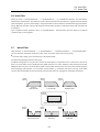
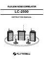
FUJI LEAK NOISE CORRELATOR
LC-2500
INSTRUCTION MANUAL
Instruments for the location of underground utilities and water leaks.
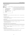
Preface
This manual describes the Fuji leak noise correlator Model: LC-2500.
Before using your equipment, be sure to read this manual to comprehend proper operating and handling procedures.
Applicability
Pick-ups are mounted to the fittings such as fire hydrant, valve, or meter on the underground piping to capture the
leak noise and identify the leak position.
1
Precautions
Before using this correlator, completely read and comprehend the safety notes listed below.
● Follow the instructions and procedures described in this manual to operate this instrument.
● Always observe the precautions indicated on this instrument and manual.
<Symbols>
The following symbols are used in this manual for the purpose of warning so that you can avoid property and
personal damages.
WARNING
This symbol indicates the existence of a potential danger that may
cause death or serious injury.
CAUTION
This symbol indicates the existence of a potential danger that may
cause slight or moderate injury.
CAUTION
This symbol indicates the existence of a potential danger that may
cause serious damage of LC-2500 or surrounding properties.
WARNING
●
●
●
●
●
●
While listening the leak noise with a headphone set during the operation of this unit, be completely
careful since it will be difficult to hear the background sounds.
Do not replace the batteries and/or operate this unit with wet hands.
When the batteries have been mounted to the battery box, handle this unit with great care. If the terminals
are short-circuited, heat generation, bursting, fire, and/or injury will occur.
When inserting the batteries into the battery case, pay attention to the polarity. Incorrect polarity will
result in leakage, heat generation, damage, and other troubles.
Do not put the batteries into the fire. Otherwise, you will suffer from bursting, fire, and/or injury.
Do not disassemble the batteries. Otherwise, you will suffer from bursting, fire, and/or injury.
2
CAUTION
●
●
●
Do not hold the handle to swing the detector.
Mount the battery cover certainly. Otherwise, the battery box may come off.
Do not swing the pick-up.
CAUTION
●
●
●
●
●
●
●
●
●
●
●
●
Do not leave or install this unit in a hot place. Otherwise, the detector may fail.
Use this unit only for the leak noise detection.
This detector is not a complete waterproof model.
Avoid immersion into water or operation in the rain.
Do not drop the detector nor apply strong impact to it.
Do not disassemble the detector.
Do not touch the panel display strongly. Otherwise, the detector may fail.
When the detector will not be used for a long period, remove the batteries.
Do not bend the antenna by applying unreasonable force.
Do not pull the pick-up cable unreasonably. Otherwise, the cable may be broken to dysfunction the
pick-up.
Always be aware of the ambient conditions.
When disposing this detector, follow your local rules and regulations.
3
Warranty Period
FUJI TECOM warrants this correlator LC-2500 to be free from defects in material and/or workmanship for one
(1) year from the purchase.
The written warranty is an effective tool with which FUJI TECOM can provide utmost service operations to the
customer.
If this correlator fails within the warranty period, FUJI TECOM will repair it free of charge.
The repair within the warranty period needs showing the written warranty with the serial numbers of this
instrument. So the customer should keep it carefully.
If the customer does not or fails to notify its serial numbers, FUJI TECOM will claim repair fees.
If this correlator fails after the expiration of the warranty period or the failure is attributable to customer’s abuse,
misuse, modification, and any other unauthorized actions, the repair will be non-gratuitous. Please consult FUJI
TECOM for details.
4
Table of Contents
< Main unit, pre-amplifier, and pick-up sensor >
1. System Components
1-1
7
Component List
7
2. Equipment Description
8
2-1 Panel and Switches (Main Unit)
8
2-2 Panel and Switches (Pre-amplifier)
10
2-3
Pick-up Sensor
12
3. Pre-operation Check
13
3-1 Checking and/or Replacing the Batteries (Main Unit)
13
3-2
15
Backup Battery
3-3 Checking and/or Replacing the Batteries (Pre-amplifier)
16
3-4 Inspection of Pre-amplifiers
18
3-5 Comprehensive Inspection
19
3-6 Setup of Date and Time
20
4. Operating Procedure
21
4-1 Radio and Cable Modes
21
4-2 Example of Operation
22
4-3 False Leak Noise
22
4-4 Preparations
23
4-5 Preparation at Site
25
4-6
27
Menus on Main Unit
4-7 Menu on Main Unit - Main Menu
29
4-8 Basic Data Input Operation on Main Unit
44
4-9 Menus on Pre-amplifier
45
4-10 Pre-amplifier Menu
46
4-11 Self-Check Function of Pre-amplifier
46
4-12 Forced Turn-off Function
47
4-13 Pick-up sensor Mount Hook
47
4-14 Listening with headphone
48
5
5. Practice
49
< Main Unit >
5-1 Pipe Data Handling
49
5-2 Waveform Monitor Function
51
5-3 White Noise Method
51
5-4 Leak Noise Record Function
56
5-5 Evaluation of Detected Position
56
5-6 Auto Filter
57
5-7 Notch Filter
57
5-8 Manual Calculation of Sound Velocity
58
5-9 LCD Contrast
59
5-10 Data Transfer to PC
59
< Pre-amplifier >
5-11 Automatic Sensitivity Adjustment
60
6. Preservation
61
6-1 Storage Method
61
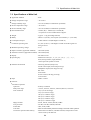
7. Technical Data
62
7-1 Definitions
62
7-2 Principle of Leak Noise Correlator
63
7-3 Specifications of Main Unit
64
7-4 Specifications of Pre-amplifier
66
7-5 Specifications of Pick-up Sensor
67
8. Troubleshooting
68
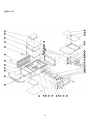
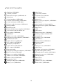
Pats list of Main Unit
70
Pats list of Pre-amplifier
72
Pats list of Pick-up sensor
74
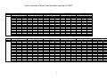
List for Velocity of Each Pipe Diameter used by LC-2500
76
6
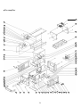
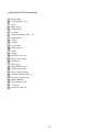
1. System Components
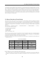
1-1 Component List
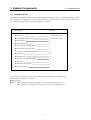
1-1 Component List
This leak noise correlator LC-2500 consists of the following components. After you purchased the detector, check
the components for completeness. FUJI TECOM performs a complete inspection before shipment. However, if
you find missing component (s), immediately inform us of the fact.
Designation
Quantity
●
Main Unit
1 (with battery case)
●
Pre-amplifier (blue and red)
2 (with battery case)
●
Pick-up Sensor
2
●
Stereo Headphones
1
●
Receiving antenna (Main Unit)
1
●
PC soft with connecting cable
1
●
LC-2100’s sensor connecting cable
2
●
Alkali battery
16
●
Shoulder strap
1
●
Spare fuse (2A, slow blow type)
1
●
Waist strap
1
●
Aluminum carrying case
1
●
Instruction manual
1
For the correlator operated outside Japan, the following components are available as the
optional items if circumstances require.
●
●
Battery charger: 1
Battery : Battery pack for main unit (composed of four size D Ni-Cad batteries) 1 ea.
Battery pack for pre-amplifiers (composed of six size D Ni-Cad batteries) 2 ea.
7
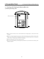
2. Equipment Description
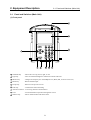
2-1 Panel and Switches (Main Unit)
2-1 Panel and Switches (Main Unit)
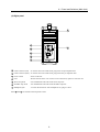
(1) Front panel
7
8
1
7
8
9
4
5
6
1
2
3
9
CURSOR
0
Enter
Light
Monitor
Delete
Escape
2
3
4
5
6
1 CURSOR key
: Moves the cursor up, down, right, or left.
2 Light key
: Turns on/off the backlight for membrane switches and LCD.
3 Monitor key
: Changes the output style to the headphone set. (Blue, Red, or Stereo can be set.)
4 Delete key
: Deletes the data input.
5 Escape key
: Returns to the previous screen.
6 Enter key
: Confirms the menu and setting.
7 Antenna connector : A receiving antenna is mounted here.
8 LCD
: You should make an operation through this screen.
9 Numeric key
: Enters numerical data and selects items.
8
2-1 Panel and Switches (Main Unit)
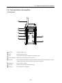
(2) Right panel
15
10
16
11
12
13
PUSE
14
10 Cable connector (red) : To use the unit in the cable mode, plug in the red pre-amplifier here.
11 Cable connector (blue) : To use the unit in the cable mode, plug in the blue pre-amplifier here.
12 Power switch
: Turns on the unit.
13 Fuse
: Protects the unit from over current. In case of blowout, replace it with new one.
14 Waist strap hook
: You should hook both ends of the waist strap here.
15 Shoulder strap hook
: You should hook both ends of the shoulder strap here.
16 Headphone jack
: To listen the leak noise with a headphone set, plug in it here.
Items 14 and 15 are located on the left panel as well.
9
2-2 Panel and Switches (Pre-amplifier)
2-2 Panel and Switches (Pre-amplifier)
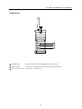
(1) Front panel
1
2
3
4
Select
Adjust
Light
Enter
5
7
Speaker
6
Power
8
1 Antenna
: Transmits radio waves.
2 Hook
: Hooks the pick-up sensor
3 LCD
: You should control the pre-amplifier through this screen.
4 Select/Adjust key : Selects the setting and adjusts the sensitivity.
5 Light key
: Turns on/off the backlight for membrane switches and LCD. While this Light key is active,
a light symbol is observed on the upper right corner of the LCD.
6 Speaker key
: Turns on/off the speaker.
7 Enter key
: Changes the menu and confirms the setting.
8 Power key
: Turns on/off the pre-amplifier.
10
2-2 Panel and Switches (Pre-amplifier)
(2) Right panel
9
10
11
9 Headphone jack
: To listen the leak noise with a headphone set, plug in it here.
10 Cable connector
: To use the pre-amplifier in the cable mode, plug in the cable here.
11 Pick-up input connector : The pick-up is connected here.
11
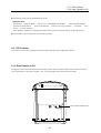
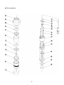
2-3 Pick-up Sensor
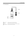
2-3 Pick-up Sensor
3
4
1
2
1 Pick-up sensor
: Detects the leak noise at the measurement point.
2 Magnet
: Allows the pick-up to attract a pipe or other target.
3 Pick-up cord
: Sends the signals acquired with the pick-up to the pre-amplifier.
4 Pick-up connector : Connects the pick-up and pre-amplifier.
12
3. Pre-operation Check
3-1 Checking and/or Replacing the Batteries (Main Unit )
3-1 Checking and/or Replacing the Batteries (Main Unit)
(1) Checking the battery power
Battery power indicator
CURSOR
7
8
9
4
5
6
1
2
3
0
Light
Monitor
Delete
Enter
Escape
●
Before using the correlator, be sure to check the batteries have enough capacity. To this end, turn on the
main unit.
●
When it is not fully charged, the open space is observed in the battery power indicator as shown in the
figure above. This open space is enlarged as the main unit consumes the battery power. If the battery
power indicator is flashing, replace the batteries immediately.
●
Before the replacement, be sure to turn off the main unit.
●
Fuji Tecom recommends that you should prepare spare batteries to cope with the runout of battery power
during the operation.
13
3-1 Checking and/or Replacing the Batteries (Main Unit )
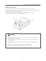
(2) Removing and attaching the battery cover and replacing the batteries
The main unit needs four (4) commercially available size D alkali dry batteries (LR20)
●
When other batteries are used, the continuous operating time of the detector will differ from the specification
described herein due to difference in battery capacity.
Remove the battery cover, take out the battery box, and replace the old batteries with new ones.
After reinsertion of battery box, be sure to remount the battery cover.
Spin a latch 90 degrees
Terminal post
Latch
WARNING
●
If those batteries that are not specified by FUJI TECOM are used and resultantly the detector fails,
the warranty statement will be invalid.
●
When replacing batteries, be careful of their orientations. Incorrect orientation will cause bursting,
fire, and/or injury.
●
Do not mount different types of batteries mixing in the battery box. Otherwise, bursting or leakage
will occur.
●
Dispose of the replaced batteries according to your local rules and regulations.
●
Pay attention not to dispose of the battery box together with the batteries.
14
3-2 Backup Battery
3-2 Backup Battery
A data backup battery is built in the main unit. This battery is used to count dates and times and store the recorded
leak noise data. This secondary vanadium coin battery is rechargeable. After the main unit is turned on, the secondary
battery is automatically charged with the main batteries. Therefore, when the main unit stands for longer period,
the secondary battery is self-discharged to decrease the power level. If the backup battery is completely discharged,
the date, time, and recorded leak noise data are lost. After the main unit has been turned off for a long period,
check the date and time for correctness after power-on. If they differ from the current ones, provide resetting by
referencing Section 3-6 “Setup of Date and Time”.
●
For the reference purpose only, about one-hour charging can retain the data for about one to two weeks.
●
Other data will not be erased.
●
The backup battery is not fully charged before the shipment. Fuji Tecom recommends you to turn on the main
unit to charge this backup battery after the equipment is delivered to you.
15
3-3 Checking and/or Replacing the Batteries (Pre-amplifier)
3-3 Checking and/or Replacing the Batteries (Pre-amplifier)
(1) Checking the battery power
PLEASE REPLACE
THE BATTERIES.
Select
Adjust
Light
Enter
Speaker
Power
●
There are blue and red pre-amplifiers. Check both units, respectively.
●
Before using the pre-amplifiers, be sure to check the batteries have enough capacity. To this end, press the Power
switch on each pre-amplifier. Each unit is equipped with the self-check function that always monitors the battery
voltage. After the pre-amplifier is turned on, it checks the battery voltage first of all and, if the voltage is below
the specified level, the message “Change batteries” appears on the LCD. When this is your case, replace the
batteries with new ones. If the LCD is turned off during the self-check, replace the batteries as well.
●
Fuji Tecom recommends that you should prepare spare batteries to cope with the runout of battery power during
the operation.
16
3-3 Checking and/or Replacing the Batteries (Pre-amplifier)
(2) Replacing the batteries
Each pre-amplifier needs six (6) commercially available size D alkali dry batteries (LR20)
●
When other batteries are used, the continuous operating time of the detector will differ from the specification
described herein due to difference in battery capacity.
Remove the battery cover, take out the battery box, and replace the old batteries with new ones.
After reinsertion of battery box, be sure to remount the battery cover.
WARNING
●
If those batteries that are not specified by FUJI TECOM are used and resultantly the detector fails,
the warranty statement will be invalid.
●
When replacing batteries, be careful of their orientations. Incorrect orientation will cause bursting,
fire, and/or injury.
●
Do not mount different types of batteries mixing in the battery box. Otherwise, bursting or leakage
will occur.
●
Dispose of the replaced batteries according to your local rules and regulations.
●
Pay attention not to dispose of the battery box together with the batteries.
17
3-4 Inspection of Pre-amplifiers
3-4 Inspection of Pre-amplifiers
There are blue and red pre-amplifiers. Check both units respectively using the same procedures.
(1) Plug the pick-up in the pre-amplifier.
(2) Press the Power switch.
(3) Press the Enter key and tap lightly on the pick-up magnet. This time, check the level indicator oscillates. If the
indicator is standstill or moves slowly, the pick-up may be faulty. Plug in another pick-up and repeat checking.
Otherwise, change the pre-amplifier and conduct the same checking. If the level indicator normally oscillates on
another pre-amplifier, the former unit may be faulty.
Level Indicator
Le v el
:
Au
to
:
4
LCD Screen on Pre-amplifier
18
.
V
3-5 Comprehensive Inspection
3-5 Comprehensive Inspection
(1) Main unit and pre-amplifiers
●
Checking the signal transmission and receive performance in radio communications
1 Turn on both the main unit and blue pre-amplifier.
2 The symbol shown left appears on the upper section of the main unit LCD. No indication shows
the signals from the pre-amplifier do not reach the main unit. If this is your case, the main unit
cannot receive the signals due to environmental conditions or the pre-amplifier’s transmission
system or the main unit’s receiving system may be faulty. Conduct the same checking for the red
pre-amplifier (R is observed instead of B).
(2) Main unit and pick-up sensors
●
Checking the correlation
1 Plug the pick-ups in both the blue and red pre-amplifiers respectively and turn on the units.
2 Turn on the main unit.
3 Access the main menu of the main unit and select “2. CORRELATION”.
4 Rub the pick-up magnets (bottom surfaces) each other.
5 Check the following operation result and correlation waveform appears on the correlation screen.
The delay time is Td=0.0 ms. The peak correlation waveform is displayed at the position where
this delay time is 0.0 ms.
Note 1 : Do not rub the pick-ups strongly. Otherwise, Td might not be 0.0 ms.
Note 2 : When contaminants such as mud are adhered to the magnet, Td might not be 0.0 ms. Before checking,
remove these contaminants.
19
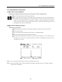
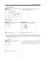
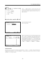
3-6 Setup of Date and Time
3-6 Setup of Date and Time
The current time (last two digits of Christian Era, month, day, hour, minute, and second) is displayed on the upper
right corner of the LCD. Check the date and time. If they differ from the current ones, conduct resetting according
to the following procedure. The date and time determined will be saved together with the measured data and,
therefore, you should provide correct setting.
Select “ 0. STATUS SETUP ” from the main menu.
Select “ 3. DATE/TIME ADJUSTMENT ” from the main
menu.
The cursor appears. Move the cursor to the parameter you
want to change and enter the value. Then, press the Escape
key. The previous screen reappears. This sets the new date
and time.
20
4. Operating Procedure
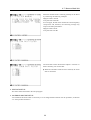
4-1 Radio and Cable Modes
4-1 Radio and Cable Modes
(1) Radio mode
Select
Adjust
Select
Adjust
Light
Enter
7
8
9
4
5
6
Light
Enter
Speaker
Speaker
CURSOR
1
2
0
3
Enter
Power
Power
Light
Monitor
Delete
Escape
Leak position
(2) Cable mode
This mode is used when the radio communications cannot be established between leak detector and pre-amplifiers
due to interference with buildings and the like or the radio waves interfere with those emitted from any radio
stations. Usually, the leak detection is implemented under the radio mode shown in (1) above.
Cable draum(option)
Connecting cable(option)
Select
Adjust
Select
Adjust
Light
Enter
7
8
9
4
5
6
Light
Enter
Speaker
Speaker
CURSOR
1
2
0
3
Enter
Power
Power
Light
Monitor
Delete
Escape
Leak position
21
4-2 Example of Operation
4-3 False Leak Noise
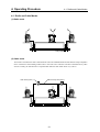
4-2 Example of Operation
This section describes how to operate the leak detection for the pipe shown below.
In this example, it is assumed that the water leaks from a certain position of the pipe.
The pre-amplifiers detect the leak noise and send the signals to the main unit.
Select
Adjust
Select
Adjust
Light
Enter
7
8
9
4
5
6
Light
Enter
Speaker
Speaker
CURSOR
1
2
0
3
Enter
Power
Power
Light
Monitor
Delete
Escape
Pipe length
Leak position
4-3 False Leak Noise
When the blue and red pick-ups detect other noise than leak noise, the correlator will identify the noise source as
leak position and display the data on the LCD. When the correlator reports the leakage, you should check whether
the pipe is actually embedded and has leakage by means of another water leak detection device, bowling, and
investigation.
●
False leak noises include the following items.
(1) Friction noise between flowing water and pipe
(2) Noise generated from sewage
(3) Noise generated from flowing water
(4) Mechanical noise
22
4-4 Preparations
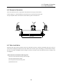
4-4 Preparations
(1) Radio mode
Select
Adjust
Select
Adjust
Light
Enter
7
8
9
4
5
6
1
2
3
Light
Enter
Speaker
Speaker
CURSOR
0
Enter
Power
Power
Light
Monitor
Delete
Escape
Pipe length
●
Insert battery boxes into the main unit and pre-amplifiers.
●
Mount the receiving antenna to main unit.
●
Plug pick-ups in the pre-amplifiers, respectively.
Leak position
* If you do not connect the pick-up sensor, an error message “No sensor connection” appears when the pre-amplifier
is turned on.
●
Turn on the main unit and pre-amplifiers.
Note : The two pick-ups must have the same specifications. The standard pick-up cannot be used together with the
pick-up for VP pipe (option).
23
4-4 Preparations
(2) Cable mode (the cable drum and connecting cable are optional)
Select
Adjust
Select
Adjust
Light
Enter
7
8
9
4
5
6
1
2
3
Light
Enter
Speaker
Speaker
CURSOR
0
Enter
Power
Power
Light
Monitor
Delete
Escape
Leak position
●
Insert battery boxes into the main unit and pre-amplifiers.
●
Arrange cables from cable drums to pre-amplifiers.
●
Plug the cable in each pre-amplifier.
●
Plug in the main unit by use of the connecting cable from each cable drum.
* Identify the blue and red pre-amplifiers to avoid illegal cable connection.
●
Plug pick-ups in the appropriate pre-amplifiers.
* If you fail to connect the pick-up, an error message “No sensor connection” appears when the pre-amplifier is
turned on.
●
Turn on the main unit and pre-amplifiers.
Note : After turning on main unit, check the following symbol appears on the LCD.
: Cable mode indication symbol
●
After pulling out the cable from the cable drum, plug it in the main unit. If the connecting cable has been connected
to the main unit in advance, the cable will be twisted and damaged by means of rotating cable drum.
24
4-5 Preparation at Site
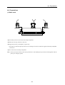
4-5 Preparation at Site
(1) Preparation of necessary conditions and data
To find the leak position with the correlator as shown below, the following four conditions as well as data
must be needed.
Select
Adjust
Select
Adjust
Light
Enter
1
Speaker
CURSOR
7
8
9
4
5
6
1
2
3
0
Light
1
Enter
Enter
Speaker
Power
Power
Light
Monitor
Delete
Escape
2
3
4
Leak position
1 The noise generated from the leak position is transmitted to both the pick-ups.
* If the noise is transmitted to only one pick-up, the leak position cannot be identified. In such the case, try to
reduce the distance between pick-ups.
* The existence of leak noise must have been identified based on the pre-investigation.
2 The material of the target pipe is identified.
* The reason is that the sound velocity (propagation speed of the leak noise) depends on the pipe material.
3 The bore of the target pipe is identified.
* The reason is that the sound velocity (propagation speed of the leak noise) depends on the bore.
4 The pipe length between pick-ups is identified.
25
4-5 Preparation at Site
(2) Installation of pick-ups
1 The candidate pick-up mount positions include fire hydrant, gate valve, and meter. Determine the mount positions
and install the pick-ups.
* Since the pick-up is completely waterproof, it can be immersed into the water.
* According to Section 3-4 “ Inspection of Pre-amplifiers ”, check the signals from each pick-up reach the appropriate
pre-amplifier.
* Check the mount positions and pick-up magnets are free from contaminants such as mud. The contaminants
may prevent correct leak detection.
2 When several leak positions exist on the same pipe (including branch pipe), determine the pick-up mount positions
so that the position that is generating the largest leak noise is located between these positions.
(3) Operation of pre-amplifiers
1 Plug the pick-up in each pre-amplifier.
* When the pre-amplifier is turned on without connection of pick-up, an error message “ No sensor connection ”
appears.
2 Tap lightly on each pick-up magnet to check signals are certainly reaching the pre-amplifier.
3 To set the sensitivity of the pre-amplifier manually, adjust it so that the normal signal level will be 5 or 6.
26
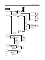
4-6 Menus on Main Unit
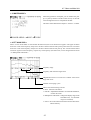
4-6 Menus on Main Unit
(1) Operation on main unit
An interactive system is employed for operations on the main unit. Operate the equipment by following the messages
displayed on the screen.
●
Start the operation from the main menu.
●
Select the desired menu with the numeric key and confirm the selection with the Enter key. (This procedure may
be omitted depending on the situation.)
●
The following indication, if observed at the bottom of the screen, shows that pressing the Escape key returns you
to the previous screen.
MAIN MENU
●
After the numerical parameters such as pipe length are input, pressing the Enter key confirms those parameters.
●
The following indication, if observed on any of screens, including leak position detect screen, selecting “ 0 ”
starts detection of leakage. Pressing up, down, right or left button of the CURSOR key changes the menu items
among “ 1. Pause ” through “ 8. Evaluation ” so that you can select the desired menu item.
0. START
27
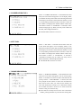
4-6 Menus on Main Unit
0
1
2
3
4
5
MEIN MENU
0 STATUS SETUP
0
1
0
1
0 Td RANGE
1 FILTER SETUP
AUTO
MANUAL
AUTO
MANUAL
50ms
100ms
200ms
400ms
800ms
1600ms
0 LOW PASS FILTER
2 PIPE DATA SETUP
3 TIME ADJUSTMENT
1 PIPE DATA SETUP
0 PIPE DATA INPUT
0 PIPE MATERIAL
1 PIPE SIZE
2 PIPE LENGTH
0 DIP
1 CIP
2 ACP
3 VP
4 LP
5 PE1
6 PE2
7 PE3
8 GP
9 SSP
10 CUP
11 etc
12 WHITE1
13 WHITE2
14 WHITE3
15 etc1
16 etc2
17 etc3
18 DIRECT
1 ~ 14 PIPE SIZE
1 PIPE DATA EDIT
2 CORRELATION
2 CORRELATION
3 WHITE NOISE
0 PIPE LENGTH
1 VELOCITY
0 PIPE MATERIAL
2 RUN
0 RUN
1 PAUSE
2 SEARTH
3 ZOOM IN
4 ZOOM OUT
5 SAVE TO WHITE1
6 SAVE TO WHITE2
7 SAVE TO WHITE3
4 FFT ANALYSIS
5 CORRELATION FILE
0
1
2
3
RECALL
DELETE
ALL DELETE
SAVE (No.0)
0
1
2
3
RUN
PAUSE
FRO.RANGE
SEVE
0
1
2
3
4
5
6
7
8
RUN
PAUSE
SEARCH
ZOOM IN
ZOOM OUT
STATUS SETUP
PIPE SETUP
SAVE
GRADING
0 1kHz
1 2.5kHz
2 5kHz
6 FFT FILE
7 NCISE RECORDING
8 MEMO
0
1
2
3
RECORDING
RECALL
DELETE
ALL DELETE
0
1
2
3
RECALL
DELETE
ALL DELETE
SAVE (No.0)
9 HELP
28
1 HIGH PASS FILTER
2 NOTCH FILTER
0
1
2
3
4
5
INPUT VELOCITY
METAL PIPE
NON METAL PIPE
SAVE TO ETC1
SAVE TO ETC2
SAVE TO ETC3
0
1
2
3
0
1
2
3
4
0
1
2
630Hz
1250Hz
2500Hz
5000Hz
THRU
80Hz
180Hz
380Hz
800Hz
OFF
50Hz
60Hz
0 O.D
1 THICK
2 YOUNG S
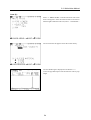
4-7 Menu on Main Unit
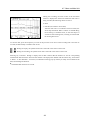
4-7 Menu on Main Unit
<MAIN MENU>
After the main unit is turned on, “FUJI TECOM” appears in
the center of the screen and changes to the main menu shown
left several seconds later. This section describes this main
menu. The current date and time appear on the upper right
corner of the screen. When the date and time are not correct,
provide resetting by referencing Section 3-6 “Setup of Date
and Time”.
0. STATUS SETUP
You can specify the Td range, filters, and date and time. In addition, you can access “ 1. Set Pipe Conditions ”
from this menu.
1. PIPE CONDITION SETUP
You can enter or change the pipe data (material, bore, and length). After the data input, you can directly access
“ 2. Leak Position Detect ” from this menu.
2. CORRELATION
You can start the detection after the necessary conditions are defined. The leak position and correlation waveform,
which were processed based on the data obtained from the measurement, are displayed. The result of operation
can be saved to the internal memory.
* The result is saved to the internal memory by selecting “ 2. Correlation” - “ 7. Save ”.
* The number of data savings is 100.
3. WHITE NOISE (Pipe Length / Sound Velocity Measurement)
When the pipe data is incomplete, you can measure the pick-up-to-pick-up distance and the sound velocity of the
leak noise through this menu to complement the data. The calculated sound velocity can be saved to the internal
memory.
The calculated sound velocity is saved to the internal memory by selecting “ 3. White Noise ” - “ 2. Measurement ” “ 5. WHITE1 ”/“ 6. WHITE2 ”/“ 7. WHITE3 ”.
4. FFT ANALYSIS
The leak noise data collected with the pick-ups is subject to frequency analysis and the result is plotted as a graph.
The result can be saved to the internal memory.
* The result is saved to the internal memory by selecting “ 4. Waveform Monitor ” - “ 3. Save ”.
* The number of data savings is 50 for blue and red pick-ups respectively (i.e., 100 in total).
29
4-7 Menu on Main Unit
5. CORRELATION FILE
The data processed with the menu “ 2. CORRELATION ” can be saved to the internal memory. This data processing
menu displays, deletes, or all-deletes the data saved.
6. FFT FILE
The data processed with the menu “ 4. FFT ANALYSIS ” can be saved to the internal memory. This data processing
menu displays, deletes, or all-deletes the data saved.
7. NOISE RECORDING
The leak noise measured with the pick-ups is recorded to the internal memory. This data processing menu records,
replays, deletes, or all-deletes the data.
* The recording time is about 16 seconds for one data set.
* Up to four data sets can be recorded.
8. MEMO
You can enter up to 227 characters showing necessary information, for example, site situation.
* Only alphanumeric and basic symbols can be used.
9. HELP
When this menu is selected, descriptions about keys and menus appear on the screen.
* The data save function will be discussed in Chapter 5 “Practice” in detail.
30
4-7 Menu on Main Unit
< 0 : STATUS SETUP >
When “0. STATUS SETUP” is selected from the main
menu, the screen shown left appears.
This screen contains the previously set values.
0. Td RANGE SETUP
You can specify the Td range (delay time). Two modes, automatic and manual, are available and the automatic mode
has already been selected as shipping default. Normally, you should use the automatic mode. When the manual mode
is selected, TdMax is displayed in the pipe condition setup menu and, therefore, you should specify Td so that it
will not exceed the maximum value.
1. FILTER SETUP
You can specify high-pass, low-pass, and notch filters.
Two modes, automatic and manual, are available and the
automatic mode has already been selected as shipping
default. Normally, you should use the automatic mode.
31
4-7 Menu on Main Unit
When the manual mode is selected, generally set the filters
by referencing the following examples.
High-pass filter: 380 Hz
Low-pass filter: 2500 Hz
For resin pipes, the leak noise contains lots of low-frequency
components and, therefore, the following settings may
improve the filter performance.
High-pass filter: 80 Hz
Low-pass filter: 630 Hz
The notch filter will be discussed in Chapter 5 “Practice” in
detail. Generally, turn on this filter.
●
When the automatic mode has been selected, the notch
filter is turned off.
2. PIPE DATA SETUP
This menu will be discussed in the next paragraph.
3. CALENDAR AND TIME SETUP
You should use this menu when it is necessary to set or change the date and time. For the procedure, see Section
3-6 “ Setup of Date and Time ”.
32
4-7 Menu on Main Unit
< 1 : PIPE DATA SETUP >
0. PIPE DATA INPUT
After “ 1. PIPE DATA SETUP ” is selected from the main
menu, the screen shown left appears. This screen contains
the previously set values. You can enter the material, bore,
and length of the pipe.
Select “ 0. PIPE DATA INPUT ”. A part of the pipe material
list appears at the bottom of the screen as shown left. Move
up or down the cursor with the up or down button of the
CURSOR key to find and select the material number corresponding to the embedded pipe.
After the material is confirmed, the cursor appears on the
bore. A part of the bore list appears at the bottom of the
screen, as seen in the material. Move up or down the cursor
with the up or down button of the CURSOR key to find
and select the bore number.
33
4-7 Menu on Main Unit
After the confirmation, the cursor appears on the length.
Enter the pipe length with the numeric keys.
When you intend to measure multiple pipes, enter the
parameters to “B” and following fields one after another.
1. PIPE DATA EDIT
You can change or add the pipe data. For the data input, see the previous paragraph.
2. LEAK POSITION DETECT
This function will be discussed in the next paragraph “ 2 : CORRELATION ”.
34
4-7 Menu on Main Unit
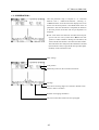
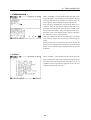
< 2 : CORRELATION >
After the parameter setup is complete in “ 0 : STATUS
SETUP ” and “ 1 : PIPE DATA SETUP ”, selecting “ 2.
CORRELATION ” from the main menu displays the screen
shown left. The leak position is calculated based on the set
parameters. After the calculation is completed, the distances
to the leak position from blue and red pre-amplifiers are
displayed.
●
▲
▲
This screen shows the distances from blue and red pickups are both 0 m. The symbol shows
that the leak
position is under calculation. During the calculation, the
value in SUM at the bottom is increased one after another.
This value shows how many times the calculation is iterated
(the maximum is 999). Larger SUM value provides higher
reliability of the calculation result.
Filter settings
}
Leak position
Maximum position on the correlation waveform.
Td range
Vertical axis showing degree of correlation. Smaller value
results in better correlation.
Number of averaging summation
The menu will be discussed in the next paragraph.
35
4-7 Menu on Main Unit
About menu
0. RUN
You should select this menu to start the calculation. To recollect the data, select “1. PAUSE ” once and start the
calculation.
1. PAUSE
This menu suspends the calculation. To resume the calculation, select this “ 1. PAUSE ” again. When you press
“ 0. START ” mistakenly, the current calculation result is cleared and the calculation is initiated from the
beginning (i.e., SUM is reset to 0). Basically, when you want to go to the next sequence (such as save) from the
calculation process, be sure to activate this pause function.
2. SEARCH
When this menu is selected, the cursor appears on the correlation
waveform. As a default, the cursor is automatically located
at the position with the highest degree of correlation. You
can move the cursor horizontally with left and right buttons
of the CURSOR key. Move the cursor when several correlation
peaks are observed. When the cursor is moved, Td, Blue,
and Red values are changed accordingly.
When “ 2. SEARCH ” is selected again, the cursor disappears.
3. ZOOM-UP
This menu magnifies the horizontal axis of the correlation waveform.
4. ZOOM-DOWN
This menu reduces the horizontal axis of the correlation waveform.
5. 0 : STATUS SETUP
This menu allows you to enter into the condition setup screen.
6. 1 : PIPE DATA SETUP
This menu allows you to enter into the pipe condition setup screen.
7. SAVE
This menu saves the measured leak position data to the internal memory.
8. EVALUATION
This menu will be discussed in Chapter 5 “ Practice ”.
36
4-7 Menu on Main Unit
< 3. WHITE NOISE >
When the pipe data is incomplete, you can measure the pickup-to-pick-up distance and the sound velocity of the leak
noise through this menu to complement the data.
This menu will be discussed in Chapter 5 “ Practice ” in detail.
< 4. FFT ANALYSIS >
When “ 4. FFT ANALYSIS ” is selected from the main menu, the screen shown below appears. The upper waveform
shows the result of the frequency analysis for the data collected with the blue pick-up while the lower waveform
shows the result of the frequency analysis for the data collected with the red pick-up. The vertical and horizontal
axes show signal level and frequency, respectively. The frequency (horizontal axis) can be changed with the menu
“ 2. FREQUENCY RANGE ”.
Frequency range
Frequency and maximum signal level
Magnification factor of vertical axis. Smaller value shows
larger leak noise.
Number of averaging cycles
Menu. It has the following contents.
0. RUN : Starts the calculation.
1. PAUSE : Suspends the calculation. To resume the calculation,
reselect this menu.
2. FREQUENCY RANGE : Changes the display range of the
horizontal axis (1, 2.5, and 5 kHz
ranges are available).
3. SAVE : Saves the measured waveform monitor data to the
internal memory.
37
4-7 Menu on Main Unit
< 5.CORRELATION FILE >
When “ 5. CORRELATION FILE ” is selected from the main
menu, the screen shown left appears. You can display, delete,
or all-delete the leak position data saved. Selecting the desired
item displays the list that contains data file numbers as well
as corresponding measurement dates and times. Select the
file number to be displayed or deleted with the numeric key,
and confirm it. When “ 2. All DELETE ” is selected, a confirmation message pops up. When you really want to delete all
the data, acknowledge the deletion.
●
The deleted data cannot be recovered.
< 6.FFT FILE>
When “ 6. FFT FILE ” is selected from the main menu, the
screen shown left appears. You can display, delete, or alldelete the waveform monitor data saved. Selecting the desired
item displays the list that contains data file numbers as well
as corresponding measurement dates and times. Select the
file number to be displayed or deleted with the numeric key,
and confirm it. When “ 2. All DELETE ” is selected, a
confirmation message pops up. When you really want to
delete all the data, acknowledge the deletion.
●
The deleted data cannot be recovered.
< 7.NOISE RECORDING>
When “ 7. NOISE RECORDING ” is selected from the main
menu, the screen shown left appears. You can record, replay,
delete, or all-delete the leak noise data collected with the
pick-ups. When “ 0. RECORDING ” is selected, the main
unit prompts the file number to which the recorded noise
data will be saved. After you select the file number, the
main unit furthermore prompts you to determine whether
the recorded noise data is saved or not. If the current file
number is OK, press the Enter key.
●
If the data has already been saved to the selected file
number, pressing the Enter key will erase the existing data.
38
4-7 Menu on Main Unit
During the recording, the same screen as the waveform
monitor is displayed as shown left. While the leak noise is
being recorded, the following menus are active.
0. RUN
1. PAUSE (also used for reexecution)
After the leak noise is recorded for sixteen seconds, the
screen stops movement. When “ 0. RUN ” is selected during
the recording or standstill mode, or after the elapse of
sixteen-second recording time, recording is restarted and
the existing data is lost.
To save the data, press the Escape key to return to the previous screen. Even if the recording time is less than 16
seconds, the data already recorded will be saved.
: During the replay, the symbol shown left is observed in the center of the screen.
: During the recording, the symbol shown left is observed in the center of the screen.
Selecting any of menus 1 through 3 displays the list that contains data file numbers as well as corresponding
measurement dates and times. Select the file number to be displayed or deleted with the numeric key, and confirm
it. When “ 2. ALL DELETE ” is selected, a confirmation message pops up. When you really want to delete all the
data, acknowledge the deletion.
●
The deleted data cannot be recovered.
39
4-7 Menu on Main Unit
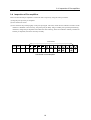
< 8. MEMORANDUM >
When “ 8. MEMO ” is selected from the main menu, the screen
shown left appears. You can enter up to 227 characters showing
necessary information, for example, site situation. First, the
cursor appears on the alphanumeric table at the bottom.
Enter the note in alphanumerics and press the Enter key to
confirm it. Now, the note appears from the upper left corner
in the frame. To edit the note, move the cursor to EDIT on the
bottom corner and select it. The cursor appears in the frame.
Move the cursor to the desired position and press the Enter
key. This allows you to enter characters.
After you complete entering the note and return to the main
menu with the Escape key, the note will automatically be
stored.
When the main unit is turned off on this memo screen, the
memo will be erased. When the Delete key is pressed on this
memo screen, all the data being displayed on the screen will
be deleted.
< 9. HELP >
When “ 9. HELP ” is selected from the main menu, the screen
shown left appears. This screen contains descriptions about
keys and menus. You should use this menu when you are not
confident on how to operate the equipment on site. The next
paragraph describes the contents.
40
4-7 Menu on Main Unit
Help menu list
●
KEY FUNCTION
0-9
: Enters numerical values or selects a menu.
.
: Enters a decimal point.
Enter
: Confirms the input.
Escape : Returns to the previous screen.
Delete
: Erases the numerical values input.
CURSOR : Moves the cursor or selects the item.
Monitor : Changes the headphone output.
Light
: Turns on/off the backlight.
●
MAIN MENU
0 : STATUS SETUP
Specifies the Td range, filters, and calendar and time.
0-0 : Td Range Setup
Selects automatic or manual setup. When the automatic mode is selected, the Td range is automatically set
based on the pipe conditions. When the manual mode is selected, you should select the Td range from the table.
0-1 : Filter Setup
Selects automatic or manual setup. When the automatic mode is selected, the main unit internally processes
the signals sent from the pick-ups and select suitable low-pass and high-pass filters, and/or notch filter.
When the manual mode is selected, you should select suitable low-pass and high-pass filters, and/or notch
filter from the table.
0-1-2 : Notch Filter
Cuts the commercial frequencies and their harmonics.
0-2 : Calendar and Time Setup
Specifies the calendar (year, month, and day) and time.
1 : PIPE DATA SETUP
You can enter or change the pipe data, and execute leak detection.
1-0 : Pipe Data Input
Specifies the material, bore, and length of the pipe.
1-0-0 : Pipe Material
You should select the appropriate pipe material from the table.
1-0-0-11 : etc
When the pipe material is unknown, you can directly enter the sound velocity or calculate the sound velocity
from the external bore, wall thickness, and Young’s modulus of the pipe.
1-0-0-11-1, 2 : Metal Pipe or Resin Pipe
You should select metal or resin pipe to calculate the sound velocity.
1-0-0-11-3, 4, 5 : Save to etc1/2/3
You can save the calculated sound velocity to etc1, 2, or 3.
1-0-0-12, 13, 14 : WHITE1/2/3
Sound velocity calculated by the white noise method.
1-0-0-15, 16, 17 : etc1/2/3
Calculated sound velocity for metal or resin pipe.
1-0-1 : Pipe bore
You should select the appropriate pipe bore from the table.
1-0-1-20 : Sound Velocity Input
You can directly enter the sound velocity.
41
4-7 Menu on Main Unit
1-0-2 : Pipe Length
You should enter the pipe length.
1-1 : Pipe Data Change
You can change the pipe data input.
2 : CORRELATION
You can detect the leak position.
2-0 : Run
Starts the leak detection.
2-1 : Pause
Suspends the leak detection.
2-2 : Search
Turns on/off the search function.
2-3 : Zoom-up
Magnifies the screen.
2-4 : Zoom-down
Reduces the screen.
2-7 : Save
Saves the measurement result.
2-8 : Evaluation
Evaluates the degree of abnormal noise detection based on the correlation waveform.
3 : WHITE NOISE
You can calculate the pick-up-to-pick-up distance or sound velocity.
3-0 : Pipe Length
You should use this menu when the length is known but the material and bore (sound velocity) are unknown.
3-1 : Sound Velocity
You should use this menu when only the material and/or bore (sound velocity) is known but the length is
unknown.
3-2 : Measurement
You can measure the pipe length or sound velocity.
3-2-5 : Save to WHITE1/2/3
You can save the measurement result.
4 : FFT ANALYSIS
You can execute the frequency analysis for the data collected with the pick-ups.
4-0 : Start
Starts the frequency analysis.
4-1 : Pause
Suspends the frequency analysis.
4-2 : Frequency Range
Sets the frequency range (horizontal axis).
4-3 : Save
Saves the result of frequency analysis.
5: CORRELATION FILE
You can display, delete, or all-delete the leak position data saved.
5-0 : Display
Displays the specified leak position data.
42
4-7 Menu on Main Unit
5-1 : Delete
Deletes the specified leak position data.
5-2 : All Delete
Deletes all the leak position data saved.
6 : FFT FILE
You can display, delete, or all-delete the waveform monitor data saved.
6-0 : Display
Displays the specified waveform monitor data.
6-1 : Delete
Deletes the specified waveform monitor data.
6-2 : All Delete
Deletes all the waveform monitor data saved.
7 : NOISE RECORDING
You can record, replay, delete, or all-delete the leak noise.
7-0 : Record
Records the leak noise.
7-1 : Replay
Replays the specified leak noise data.
7-2 : Delete
Deletes the specified leak noise data.
7-3 : All Delete
Deletes all the leak noise data saved.
8 : MEMO
You can record the necessary information, for example, site situation.
43
4-8 Basic Data Input Operation on Main Unit
4-8 Basic Data Input Operation on Main Unit
This section describes the basic flow for the detection of leak position.
●
The following flow shows the operation in wireless communication mode.
(1) Turn on the main unit, and check the battery power is enough and the equipment receives signals from each
pre-amplifier.
(2) Select “ 0 : Status Setup ” - “0. Td Range Setup ”- “ 0. Automatic Setup ”.
(3) Select “ 0 : Status Setup ” -“ 0. Filter Setup ” -“ 0. Automatic Setup ” to set the filters.
(4) Access “ 1 : Pipe Data Setup ” and enter the material, bore, and length of the target pipe.
This completes the setting necessary to detect the leak position.
(5) Select “ 2 : Correlation ”. The measurement is executed and the result appears on the screen.
To ensure the correctness of the result, manually set the Td range and filters, re-execute the measurement, and check
the change from the previous data.
●
Smaller Td range increases the resolution of data collection. Fuji Tecom recommends you to use small Td range
as far as possible when the distance between pick-ups is short.
44
4-9 Menus on Pre-amplifier
4-9 Menus on Pre-amplifier
This section describes the screen configuration on each pre-amplifier.
POWER SUPPLY
POWER SWITCH
COMPANY LOGO
F
U
L
J
C
I
D
I
T
5
E
0
C
0
O M
2
A
N
S
I
M G
C
H
A
N
O
N
N
G
E
S
C
E
O
S
B
A
T
T
N
N
S
N
O
E
R
C
T
.
A
.
!
SELF CHECKING
N
O
W
> > > > > > > > > > > > > > > >
A
I
O
N
SELECT/ADJUST SWITCH
GAIN CONTROL
S
U
ERROR
E
T
N
O
S
.
/
A
D J
M A
U
N
S
U
T
A
L
A
S
E
N
U
T
O
/
D
J
U
S
T
M
A
N
U
A
L
ENTER SWITCH
S
L
E
N
S
.
A
E
V
A
E
U
L
T
J
U
S
T
H
BY SELECT/ADJUST SWITCH
20 LEVELS SAR
CORRELATION
L
D
{
O
:
.
"
"
V
. " STANDS FOR VOLTAGE
" STANDS FOR GAIN LEVEL
L E
M A
V
N
E
U
L
A
I
D
L
:
F
I
.
V
ENTER SWITCH
SELECT/ADJUST SWITCH
FILTER SETTING
F
S
I
D
A
S
U
E N
T O
I
L
/
T
.
/
A
E
R
T
H
R
U
D J
M A
U
N
S
U
T
A
S
L
/
T
.
/
A
.
A
E
R
T
H
R
U
D J
M A
U
N
S
U
T
A
D
U
S
T
SELECT/ADJUST SWITCH
S
L
A
S
U
E N
T O
S
S
E
S
L
ENTER SWITCH
MEMBRANE SWITCH
1: POWER SWITCH (ON/OFF)
2: ENTER SWITCH
3: SELECT/ADJUST SWITCH ( ,
4: SELECT SWITCH
5: SPEAKER
TOTAL : 5 ITEMS
L
)
{
N
J
H
BY SELECT/ADJUST SWITCH
ENTER SWITCH
MARK "
" APPEARS BACK LITE IS ON
●
One-way rule is used to move in the menus. To return to the previous screen, cycle repeat the screen change
process.
●
To change and confirm the menu, use the Enter key.
45
4-10 Pre-amplifier Menu
4-11 Self Check Function of Pre-amplifier
4-10 Pre-amplifier Menu
< Sensitivity Adjustment >
You can select automatic or manual adjustment. Although the automatic adjustment will be discussed in Chapter
5 “ Practice ” in detail, selecting this mode processes the signals input from the pick-up and controls the pre-amplifier
to a certain sensitivity level. In the manual adjustment, you should control the sensitivity by yourself. This time,
set the sensitivity being careful that the level indicator will not exceeds the specified range. Fuji Tecom recommends
that you should adjust the sensitivity while listening the noise from the speaker or headphone. Listening the noise
helps you judge whether the sensitivity adjustment is appropriate or not.
●
The screen where the signal level is displayed indicates the automatic or manual adjustment mode, whichever
effective.
●
After plugging in the headphone jack, press the Speaker key.
CAUTION
●
When listening the noise with the headphone, use complete care so that you will not hurt your ears.
< Filter >
You can select the option whether the low-band noise is filtered or not. Usually, select STD. When the waveform
monitored on the main unit contains many frequency components of less than 100 Hz, attempt the THRU setting.
The correlation may be improved.
●
Generally, external noises contain many frequency components of less than 100 Hz. Therefore, if even these
components are collected with the pre-amplifier, the measurement result may be incorrect due to influence of
unwanted noises.
4-11 Self-Check Function of Pre-amplifier
The pre-amplifier contains the following self-check functions.
(1) Battery voltage check (the error message blinks)
After the pre-amplifier is turned on, this function works first. If the battery voltage is below the specified level,
an error message appears on the screen and all the keys, except for the Power key, are disabled. This function
is always working and, when the battery voltage gets below the specified level during the measurement, the
same action will be implemented.
(2) Pick-up connection check (the error message is highlighted)
When the pick-up is still not plugged in the pre-amplifier after power-on, an error message appears and you
cannot access any other screen until the pick-up is connected to the pre-amplifier. This function prevents faulty
pick-up connection.
(3) Cable connection check
When the cable is plugged in the cable operation mode connector, the pre-amplifier automatically recognizes
the cable and cuts the power to the radio transmitter.
46
4-12 Forced Turn-off Function
4-13 Pick-up Sensor Mount Hook
4-12 Forced Turn-off Function
The power supply voltage is always monitored on the main unit and pre-amplifiers. When the battery voltage gets
below the specified level, the operation of the equipment becomes unstable and resultantly the accurate measurement
might not be continued. If the battery voltage gets below the certain reference level, the equipment is forcibly shut
down. When this shutdown occurs, the LCD is turned off. Replace the batteries with new ones.
Forced turn-off threshold (main unit)
: Less than 4.0 V
Forced turn-off threshold (pre-amplifier) : Less than 6.0 V
4-13 Pick-up Sensor Mount Hook
When you move on the site, the pick-up can be engaged to the pick-up mount hook as shown below.
47
4-14 Listening with Headphone
4-14 Listening with Headphone
After the headphone is connected to this main unit and pre-amplifiers, you can listen the noise captured by the
pick-ups. After plugging in the headphone jack, press the Speaker key.
CAUTION
●
When listening the noise with the headphone, use complete care so that you will not hurt your ears.
48
< Main Unit >
5-1 Pipe Data Handling
5. Practice
< Main Unit >
5-1 Pipe Data Handling
Red
pre-amplifier
(R)
Blue
pre-amplifier
(B)
PE1 20
PE1 20
3.5m
4.9m
DIP75 41m
This section describes the data handling based on the example where three different types of pipes exist as shown
above.
●
To detect the leak position based on the multiple pipe data sets as shown in this example, be sure to enter the data
starting from the blue pre-amplifier.
●
Up to six pipe data sets, A to F, can be input.
For the data input procedure, see the relevant section in this manual.
The table below lists pipe materials and bores.
Material
Young s modulus, Mpa
Material
Young s modulus, Mpa
DIP
157000
HDPE
823
CIP
117500
PE MAINS
784
ACP
23500
SP
191000
PVC
3000
COP
124500
LEAD
15200
GALV (GP)
210000
LDPE
215
49
5-1 Pipe Data Handling
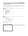
- Adding the pipe data To add the pipe data, be sure to select “ PIPE DATA EDIT ”.
When “ PIPE DATA INPUT ” is selected, new data input
mode becomes active and resultantly the data already input
is deleted. To add another pipe to “ C : ” in the condition
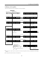
shown left, press the Enter key or CURSOR key. The cursor
moves to the Material field of “ C : ”
- Changing the pipe data To change the pipe data, be sure to select “ PIPE DATA EDIT ”.
When “ PIPE DATA INPUT ” is selected, new data input
mode becomes active and resultantly the data already input
is deleted. As shown left, move the cursor to the item you
want to change, and change the data with numeric keys.
- Deleting the pipe data To delete the pipe data, be sure to select “ PIPE DATA EDIT ”.
When “ PIPE DATA INPUT ” is selected, new data input
mode becomes active and resultantly the data already input
is deleted. As shown left, move the cursor to the Material
filed of the item you want to delete, and delete the data with
the Delete key.
●
This function deletes the data in the Material, Bore, and
Length fields of the target item.
50
5-2 Waveform Monitor Function
5-3 White Noise Method
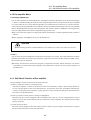
5-2 Waveform Monitor Function
This function uses DSP (Digital Signal Processor) built in the main unit and executes the FFT (Fast Fourier
Transform) operation for the leak noise data collected with pick-ups to analyze the leak noise frequencies. The
waveform monitor function can analyze the frequency components of the leak noise collected with pick-ups and
help the filter setup (manual setup).
5-3 White Noise Method
To detect the leak position with this correlator, it is necessary that the material and bore (sound velocity) of the pipe,
and the distance between pick-ups have been identified. If any of these parameters is unknown, the leak position
cannot be measured. However, a part of the pipe data may be unknown depending on the site condition. The white
noise method will be an effective solution. The white noise method can handle the following three cases.
Items to be obtained
Case
Material
Bore
Sound velocity
1
?
?
?
?
2
3
Distance
?
(Estimated value)
Using the white noise method, calculate the value identified with ? .
Upon completion of data calculation, enter the pipe data.
51
?
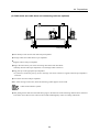
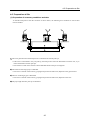
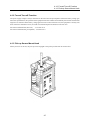
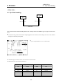
5-3 White Noise Method
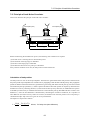
- Principe of white noise method An white noise method is mounted to the same position as the blue pick-up, and the sound velocity and pick-up-topick-up distance are calculated from the time difference generated on the vibration sounds propagating to the red
pick-up from the blue pick-up.
The following figure shows the system configuration for the white noise method. The white noise oscillator system
(composed of oscillator and vibrator) is mounted to the same position as the blue pick-up.
Pre-amplifier (red)
Pre-amplifier (blue)
White noise
generator
Select
Adjust
Light
Battery (12 VDC)
Select
Adjust
Enter
7
8
9
4
5
6
1
2
3
Light
Enter
Speaker
Speaker
CURSOR
0
Power
Oscillator
Enter
Power
Light
Monitor
Delete
Escape
Leak position
Caution
The white noise method can be used as long as the section between the pick-ups consists of only one pipe.
When multiples pipes exist between the pick-ups, this method is invalid.
●
The white noise oscillator system is optional unit.
Please contact Fuji Tecom Inc. about its details.
The following paragraphs describe concrete operating procedures.
52
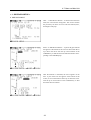
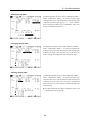
5-3 White Noise Method
Case (1) :
Select “ 3. WHITE NOISE ” from the main menu. The
screen shown left appears. Since the pipe length is known
but the sound velocity is unknown in this case, select “ 0.
PIPE LENGTH ”.
The screen shown left appears.
Enter the pipe length.
Return to the white noise screen with the Escape key and
select “ 2. RUN ”. Although the values and calculation result
are not shown in this screen, the calculated sound velocity is
actually displayed in the field of “ V ”. Also, the input values
are displayed in the parentheses. You can save the calculated
value to the internal memory. To this end, use the menu “ 3 2 : RUN ” - “ 5. WHITE1 ” “ 6. WHITE2 ” “ 7. WHITE3 ”.
<Saving the data>
Basically, use the same operation as the leak position data. Select “ 3-2 : RUN ” - “ 1. PAUSE ” during the measurement.
Change the menu and select “ 3-2-5 : Save to WHITE1 ”. The data will be saved to 1-0-0-12, 1-0-0-13, or 1-0-0-14
(WHITE1, 2, or 3 for pipe material).
53
5-3 White Noise Method
Case (2) :
Select “ 3. WHITE NOISE ” from the main menu. The screen
shown left appears. Since the material and bore are known
but the length is unknown in this case, select “ 1. VELOCITY ”
The screen shown left appears. Enter the sound velocity.
The calculated length is displayed in the field of “ L ”.
Access the pipe data input screen and enter the value as pipe
length.
54
5-3 White Noise Method
Case (3) :
In this case, both the bore (sound velocity) and length of the pipe are unknown and, therefore, the sound velocity
data obtained from the pipe material type is input as an estimated value to temporarily detect the leak position.
For the sound velocities, see the table below.
●
The speed of the leak noise propagating inside the pipe generally depends on the material and bore. Metal pipes
provide higher sound velocity than resin pipes while larger bore decreases the velocity for the same pipe material.
Material
Bore, mm
Sound velocity, m/s
Ductile iron pipe (DIP)
75 ~ 1500
1341 ~ 1039
Vinyl chloride pipe (PVC)
13 ~ 600
622 ~ 344
Polyethylene pipe (LDPE)
10 ~ 50
314
Polyethylene pipe (HDPE)
10 ~ 50
314 ~ 311
Select “ 3. WHITE NOISE ” from the main menu. The screen
shown left appears. Both bore and length are unknown in this
case. Therefore, estimate the sound velocity from the material
and enter the estimated value.
Select “ 1. VELOCITY ”.
The screen shown left appears. Enter the estimated sound
velocity. Select “ 18. DIRECT ” from “ 3-1-0. Pipe Material ”.
55
5-4 Leak Noise Record Function
5-5 Evaluation of Detected Position
The calculated length is displayed in the field of “L”.
Access the pipe data input screen and enter the value as pipe
length.
Caution
The distance, L, is calculated from the estimated sound
velocity and, therefore, L is an approximate value.
5-4 Leak Noise Record Function
You can record and replay the leak noise data collected with pick-ups. In addition, the frequency analysis can be
executed using the waveform monitor function. This means that during the record or replay process you can access
the result of frequency analysis on the waveform monitor screen while listening the leak noise.
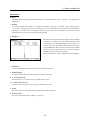
5-5 Evaluation of Detected Position
When “ 1. PAUSE ” - “ 8. GRADE ” is selected on the
Correla-tion screen, the screen shown left appears. This
screen shows the degree of correlation evaluated based on
the leak position measurement. The evaluation is
classified into three ranks,
A, B, and C.
A : HIGH CONFIDENCE FACTOR.
B : LOW CONFIDENCE FACTOR.
C : NO CONFIDENCE FACTOR.
This evaluation is based on the correlation waveform and, therefore, you should use it as a guideline. Even when
the evaluation result “ A ” is reported, there is necessarily no leakage.
56
5-6 Auto Filter
5-7 Notch Filter
5-6 Auto Filter
When you select “ 0. STATUS SETUP ” - “ 1. FILTER SETUP ” - “ 0. AUTOMATIC SETUP ”, the leak detector
automatically sets the filters. This function executes the FFT operation for the leak noise signals sent from the blue
and red amplifiers, processes the frequency components under certain conditions, and determines appropriate filter
setting. Basically, the filter setting is determined so that the major frequency components of the leak noise data will
be included.
Upon completion of FFT operation, select “ 5. FILTER SETUP ” from the menu. Now, the filters are set and the
condition setup screen reappears.
5-7
Notch Filter
After selecting “ 0. STATUS SETUP ” - “ 1. FILTER SETUP ” - “ 1. MANUAL SETUP ” - “ 2. NOTCH FILTER ”,
you can select the notch filter setting from OFF, 50 Hz, and 60 Hz. OFF is the normal setting.
●
The notch filter setting can be selected only in the manual mode.
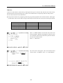
The following paragraph describes filter types.
In addition to high-pass or low-pass filter, which cuts the frequency components above or below the certain level,
there are various filters such as band-pass filter (BPF) that passes a certain frequency band, band-rejection filter
(BRF) that does not pass a certain frequency band to some extent (this filter does not remove the relevant frequency
band completely and, therefore, it is not called “ band-cut filter ”), notch filter (NF) that is one type of the bandrejection filter and handles the narrower band, and comb filter that is an aggregation of multiple notch filters.
Sound
volume
Sound
volume
Low
Frequency
High
Sound
volume
Low
Frequency
High
Low
Low-pass filter
High-pass filter
Frequency
High
Band-pass filter
Sound
volume
Low
Frequency
High
Original frequency characteristics
Sound
volume
Sound
volume
Low
Frequency
High
Band-rejection filter
Low
Sound
volume
Frequency
Notch filter
57
High
Low
Frequency
Comb filter
High
5-8 Manual Calculation of Sound Velocity
As shown above, the notch filter cuts the components in a certain frequency band. Although multiple notch filters
are combined in this leak detector and thus it may be appropriate to essentially call comb filter, the word “ notch
filter ” is used for the sake of convenience. Five notch filters are used to process the 50 Hz and 60 Hz frequency
bands, respectively. For 50-Hz band mode, the filters cut the harmonics in 50, 100, 150, 200, and 250 Hz bands.
For 60-Hz band mode, the filters cut the harmonics in 60, 120, 180, 240, and 300 Hz bands. When it is likely that
pick-ups acquire the harmonics in 50 and 60 Hz commercial bands, Fuji Tecom recommends you to use the notch
filters in the detection of leak position.
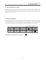
5-8 Manual Calculation of Sound Velocity
This main unit stores sound velocities of various pipes in its internal memory. Basically available pipe materials
and bores are stored to the memory, but they might not cover all the applications encountered. When parameters
of the pipe (material and bore) are known but the data is not defined in the internal memory, you can calculate the
sound velocity of the pipe from the outside diameter, wall thickness, and Young’s modulus (modulus of longitudinal
elasticity).
When selecting “ 1. PIPE DATA SETUP ” - “ 0. PIPE DATA INPUT ” - “ 0. PIPE MATERIAL ” - “ 11. ETC ”,
you can access the following options.
0. SOUND VELOCITY INPUT
1. METAL PIPE
2. RESIN PIPE
3/4/5. SAVE TO ETC 1/2/3
The reason why metal and resin pipes are separately used is that the different equations are needed although they
use the same data (outside diameter, wall thickness, and Young’s modulus) in calculation. For outside diameter,
wall thickness, and Young’s modulus, refer to the relevant standard.
●
The pipe manufacturers have the data. Since diameters and wall thickness are stipulated in the JIS standard, you
should also refer to it.
List of Young’s Modulus
●
Material
Young s modulus, Mpa
Material
Young s modulus, Mpa
DIP
157000
HDPE
823
CIP
117500
PE MAINS
784
ACP
23500
SP
191000
PVC
3000
COP
124500
LEAD
15200
GALV (GP)
210000
LDPE
215
Above figures are our survey data and for reference purpose only.
After you select metal or resin pipe and enter the outside diameter, wall thickness, and Young’s modulus, the
calculation is automatically executed. Upon completion of calculation, be sure to save the result to etc1, etc2, or
etc3.
58
5- 9 LCD Contrast
5-10 Data Transfer to PC
●
Note that the result will not automatically be saved.
Operation flow:
Selection of “ 1. METAL PIPE ” selection of “ 0. OUTSIDE DIAMETER ” input of outside diameter
selection of wall thickness
input of wall thickness selection of Young’s modulus
calculation
selection of “ 3. SAVE TO ETC 1 ”.
After the above sequence is completed, the data will be saved to the internal memory of the leak detector.
●
The saved data can be called when you enter the pipe data.
5-9 LCD Contrast
The contrast of the LCD is adjusted in the factory before shipment. Do not adjust the contrast.
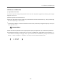
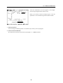
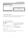
5-10 Data Transfer to PC
The data saved in the internal memory (detected leak position data, waveform monitor data, and leak noise data)
can be transferred to a personal computer (“ PC ”). The paragraph below describes the procedure.
LCD
CONTRAST
59
RS232C
Communication cable terminal
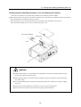
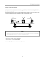
5-11 Automatic Sensitivity Adjustment
< Operating procedure >
(1) Remove the battery cover from the main unit. Place this unit with the back facing upward.
●
Do not remove the battery box from the unit.
Turn on the main unit. Note that the data cannot be transferred to the PC with the detector turned off.
(2) Prepare the communication cable specified by Fuji Tecom. Plug the communication cable in the communication
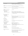
cable terminal on the leak detector and the COM port on the PC.
Proceed the operation according to “ LC-2500 for Windows : User’s Manual ”.
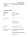
<Pre-amplifier>
5-11 Automatic Sensitivity Adjustment
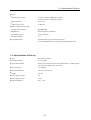
Each preamplifier is capable of automatically adjusting the sensitivity of the signals input from the pick-up. When
the input signals are weak, the sensitivity can be increased to enhance the reliability. If the sensitivity is excessively
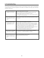
increased, the input signals are distorted to fail accurate measurement.
●
Always check the sensitivity using the level indicator. If the indicator exceeds the specified range, the data acquisition
may be illegal.
This automatic sensitivity adjustment automatically sets the signal level input from the pick-up to a certain value.
The level indicator of the pre-amplifier has ten adjustment steps, and this function, when works, adjusts the
sensitivity so that the indicator points level 5 or 6.
However, if the input signal level is extremely strong or weak, the indicator might not point 5 or 6 due to internal
processing.
60
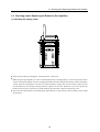
6. Preservation
6-1 Storage Method
6-1 Storage Method
When this correlator will not be used for a long period, store it according to the following procedures.
(1) Check any of the system components, including instruction manual, is not missing.
(2) Remove the batteries. If the batteries are mounted in the unit for a long period, leakage may occur to damage
the equipment.
● Before storing the batteries, cover and insulate each of them with vinyl tapes to prevent short-circuit.
(3) Do not store the batteries in a wet place.
< After Operation >
When storing the detector after operation, observe the following precautions.
(1) Clean each pick-up to remove the mud and dirt completely and place it in the storage case.
The contaminated pick-up may stain the main unit and pre-amplifiers to cause malfunctions.
(2) If the detector is wet by rain, wipe it to remove raindrops completely and place it in the storage case.
(3) Place only the detector in the storage case. Otherwise, it may be damaged or faulty.
61
7. Technical Data
7-1 Definitions
7-1 Definitions
This section describes the terms used in this manual.
●
Correlator
This equipment calculates the correlation coefficient of the signals acquired with pick-ups. The pre-amplifiers send
the signals, which have been acquired with the pick-ups mounted in two places, to the leak detector, and the leak
detector calculates the correlation coefficient of these signals, calculates the time difference between the two signal
inputs, and obtains the leak position.
●
Sound velocity
The leak detector displays the velocity of the sound propagating in the water filled in the pipe. Metal pipes provide
higher sound velocity than resin pipes while larger bore decreases the velocity for the same pipe material.
●
Filter
As already explained in Section 5-7 “ Notch Filter ”, using filters can extract only the frequency components
necessary for the measurement.
●
Td range
Td range means a delay time. The delay time refers to the time difference between the time when one pick-up
acquires a signal and the time when another pick-up acquires a signal. When a signal source exists in the center
of the span between pick-ups, the signal propagation times are identical and the time difference (Td) equals to 0.
When the signal source is close to the reference pick-up, Td will be positive value. When the signal source is far
from the reference pick-up, Td will be negative value.
●
DSP (Digital Signal Processor)
This microprocessor can process the digital signals such as audio, image, and animation signals in real time at
high speeds.
●
FFT (Fast Fourier Transform)
Concretely speaking, the FFT operation calculates the Fourier coefficients of the Fourier series. This leak detector
digitally samples the input signal waveforms, stores the sampled waveforms, executes the FFT operation for them,
and displays the result. Pick-ups acquire the time-dependent data and it is difficult to execute the frequency analysis
for the raw data. After the data is processed by the FFT operation, the frequency analysis can be executed for
those signals that alter as the time changes.
* Even when the noise acquired with the pick-ups are listened, you cannot identify the major frequency components.
(You can identify the time-dependent signal change.) After the FFT operation, the frequency analysis can be used
and, therefore, you can identify the major frequency components of the signal.
●
White noise
This noise uniformly contains all the frequency components that exist in a certain frequency band.
●
Young’s modulus (modulus of longitudinal elasticity)
When a load is applied to an object within a certain range and removed, the object completely recovers to the
original state. This property is called “ elasticity ”. The displacement is proportional to the load within the elastic
region. The relationship is expressed as follows.
σ=E·e
Where, σ : Stress
E : Young’s modulus
ε : Strain
The proportional constant E is called “ Young’s modulus ”.
62
7-2 Principle of Leak Noise Correlator
7-2 Principle of Leak Noise Correlator
This section describes the principle of the leak noise correlator.
Pre-amplifier (blue)
Pre-amplifier (red)
Select
Adjust
Select
Adjust
Light
Enter
7
8
9
4
5
6
1
2
3
Light
Enter
Speaker
Speaker
CURSOR
0
Enter
Power
Power
Light
Monitor
Delete
Escape
Leak position
N
L
L
D
Before commencing the leak detection process, the following four conditions are required.
(1) The leak noise is reaching the two measurement points.
(2) The material of the target pipe is identified.
(3) The bore of the target pipe is identified.
(4) The distance between the two pick-ups is identified.
If any of these conditions is not met, the leak position cannot be detected.
Calculation of leak position
The leak position is close to the red pre-amplifier. The leak noise generated from the leak position is detected with
the pick-up of the red pre-amplifier first. The leak noise is propagating to both the blue and red pick-ups. The propagation
speeds are identical. When the leak noise is generated at a given timing and reaches the red pick-up, it has also traveled
toward the blue pick-up by distance, L, which is equal to the distance from leak position to red pick-up. The leak noise
furthermore travels by remaining distance, N, and reaches the blue pick-up. Therefore, an additional time equal to
N divided by sound velocity is needed for the leak noise to reach the blue pick-up (this additional time is called “ time
difference” ). Since the time difference is determined by calculating the correlation coefficient, N is a product of
time difference and sound velocity. When N is known, the distance from the leak position to the red pick-up is
calculated from (D ー N) /2 since D is given as one of preconditions.
The equation is expressed as follows.
L=
D--N D-- (V x Td)
=
2
2
Where, Td: Delay time (time difference)
63
7-3 Specifications of Main Unit
7-3 Specifications of Main Unit
Applicable standard
: IP52
●
Storage temperature range
: -20 to 60°C
●
Storage humidity range
: 10 to 90 % RH (No condensation permitted)
●
Service temperature range
: -20 to 50°C
●
Service humidity range
: 30 to 90 % RH (No condensation permitted)
●
External dimensions
: 197mm (W) × 100mm (D) × 250mm (H)
* Projections are not included in these figures.
●
Weight
: Approx. 3.1 kg (including batteries)
●
Battery
: LR20 × 4 (6V DC), Ni-Cad pack (size D battery × 4, 4.8 VDC)
●
Consumption ampere
: Under 550mA at 6V (Backlight is turned on)
●
Continuous operating time
: 8 h, min. (at 20°C) * Backlight is turned on and the signals are
being received.
●
Minimum operating voltage
: 4.2 V
●
Impact resistance (applicable standard)
: JIS C0041 (1999)
●
Vibration resistance (applicable standard) : JIS C0040 (1999)
●
Display
: Dot matrix LCD
●
Operating key
: Membrane switch (0, 1, 2, 3, 4, 5, 6, 7, 8, 9, . ,
Enter, Escape, Delete, Light, Monitor)
* Some pictorial symbols are used.
●
Interface and terminal
: Receiving antenna (waterproof)
Wired control input (with waterproof cap)
Headphone output (with drip-proof cap)
RS-232C
Fuse holder
Power switch (with drip-proof cap)
LCD contrast
●
Input
: Radio or Cable
●
Function:
Correlation operation
Operation
Delay time range
Time resolution
High-pass filter
Low-pass filter
Notch filter
Auto filter
Correlative operation data memory
,
↓
↓
●
,↓,
↓
●
,
: Polarity correlation
: ±50 ms, ±100 ms, ±200 ms, ±400 ms,±800 ms, ±1600 ms
: 25 µs (in ±50 ms range)
50 µs (in ±100 ms range)
100 µs (in ±200 ms range)
200 µs (in ±400 ms range)
400 µs (in ±800 ms range)
800 µs (in ±1600 ms range)
: 80 Hz, 180 Hz, 380 Hz, 800 Hz, THRU
: 630 Hz, 1250 Hz, 2500 Hz, 5000 Hz
: OFF, 50 Hz, 60 Hz
: Filters are automatically selected according to the result of FFT operation.
: Measurement conditions, calendar and time, and operation result
can be saved by 100 data sets.
64
7-3 Specifications of Main Unit
Pipe conditions
: Pipe material (11 types), bore (XXXX mm),
sound velocity (XXXX m/s), pipe length (XXXX.XX m)
●
Manual sound velocity calculation function
Input
: Outside diameter (XXXX.X mm), wall thickness (XX.X mm),
Young’s modulus (XXXXXX MPa)
●
Automatic delay time range setup function
Conditions
: The delay time is automatically set according to Td max displayed
on the pipe condition input screen.
●
Correlation evaluation function
Rank
●
●
Waveform monitor function
Display channel
Frequency range
Monitor screen data memory
Record and replay function:
Record channel
Replay channel
Recorded data memory
Replay
●
●
●
:2
:2
: Measurement conditions, calendar and time, and recorded 16-second
noise can be saved by 4 data sets.
: The recorded noise can be listened with headphone set or displayed
on the waveform monitor.
: ASCII codes
Time count function:
Contents
Accuracy (monthly error)
: Year, month, day, hour, minute, and second (24-hour mode)
: ±1 min (at 25°C)
Memory backup function:
Backed up device
Retention time
Backup battery
: SRAM memory and real-time clock
: Approx. 2.5 months (at 25°C)
: Secondary vanadium-lithium coin battery
Key operation confirmation function
●
Backlight function:
Backlit device
●
:2
: 1 kHz, 2.5 kHz, 5 kHz (common to both channels)
: Measurement conditions, calendar and time, and operation result
can be saved by 50 data sets for blue and red pre-amplifiers respectively
(i.e., 100 data sets in total).
Note function:
Input character
●
●
: A, B, and C
Monitor function:
Headphone output
Continuous monitor function
Item
: A confirmation sound is generated from the buzzer (built in the
equipment) and headphone.
: LCD and operation keys
: Selectable from Blue, Red, and Stereo
* The current output mode is displayed on the screen.
: Battery voltage. (When the battery voltage gets below the specified
level, the warning symbol flashes at an interval of 1 s.)
Wired operation mode is detected.
Radio operation mode is detected.
* The unique symbol is displayed on the screen.
65
7-4 Specifications of Pre-amplifier
●
●
●
PC data transfer function:
Transferable data
: Correlated data, waveform monitor data, and recorded noise data.
Low-battery shutdown function:
Voltage
: 3.9 V
External interface
: RS-232C
7-4 Specifications of Pre-amplifier
●
Applicable standard
: IP52
●
Service temperature range
: -20 to 50°C
●
External dimensions
: 150mm (W) × 110mm (D) × 240mm (H)
* Antenna and Grip are not included in these figures.
●
Weight
: Approx. 2.85 kg (including batteries)
●
Battery
: LR20 × 6 (9 VDC)
●
Consumption ampere
: Under 550mA at 9 V (Backlight is turned on)
●
Continuous operating time
: 8 h, min. (at 20°C)
* Backlight is turned off and the signals are being received.
●
Minimum operating voltage
: 6.0 V
●
Display
: Character LCD
●
Operating key
: Membrane switch
(Power, Enter, Select/Adjust, Light, Speaker)
* Some pictorial symbols are used.
●
Terminals
: Pick-up input (waterproof)
Wired control input (with waterproof cap)
Headphone output (with drip-proof cap)
●
Function
●
Correlation mode
●
Amplifier gain setup mode
: Automatic or manual mode is selected.
●
Filter setup mode
: Standard (STD) or though (THRU) mode is selected.
●
Monitor function
: The speaker and headphone outputs (stereo) are monitored.
●
Power save function
: Only the backlight is supported. (When there is no key input for
3 min, this function works.)
●
Key operation confirmation function
: A confirmation sound is generated from the speaker and headphone.
●
Backlight function
: LCD and operation keys are backlit.
●
Self-check and continuous monitor function
: Battery voltage. (When the battery voltage gets below the specified
level, a warning message is issued and then the equipment is turned
off.)
Pick-up connection is detected.
Wired operation mode is detected.
66
7-5 Specifications of Pick-up
●
Input
●
Input frequency range
: 0.1 Hz to 5 kHz (at THRU filter setting)
100 Hz to 5 kHz (at STD filter setting)
●
Input sensitivity
: 50µV, max.
●
Signal to noise ratio
: 35 dB, min.
●
Radio communication system
●
Transmission frequency
: 400 MHz band
●
Modulation
: Direct frequency modulation
●
Transmitting power
: 0.5 W (500 mW)
●
Output impedance
: 50 Ω
Compatible sensor
: Amplifier built-in type acceleration pick-up,
LC-2100 standard pick-up, VP pick-up and Hydrophone sensor.
●
7-5 Specifications of Pick-up
●
Type
: Piezoelectric pick-up
●
Voltage sensitivity
: 2.5 V/g (peak)
●
Applicable standard
: IP68. (The pick-up must meet the standard after it is submerged in
the water at the depth of 2 m for 5 days.)
●
Drop resistance
: 1 m (asphalt)
●
External dimensions
: φ 30 mm x130 mm (H)
●
Weight
: 0.42 kg
●
Power supply voltage
:5V
●
Power supply system
: 3-wire
●
Output impedance
: 100 Ω, max.
67
8. Troubleshooting
The procedures described herein should be used when your leak detection system is faulty. If the appropriate
troubleshooting does not restore the equipment or the troubles are not defined in this chapter, please contact Fuji
distributor or Fuji Tecom.
(1) The main unit and/or preamplifier are not turned on :
●
(2) Keys on the mainunit and/or
pre-amplifier are not operable :
●
(3) The main unit does not receive
the radio signals or the receiving performance is poor :
●
(4) The material, bore, and length
of the pipe are not known :
●
(5) The error message does not
disappear from the pre- amplifier :
●
Check whether batteries are mounted.
Take out the battery box and replace the batteries with new ones.
● Check whether the polarity of the batteries is correct.
● Check whether the fuse is blown out. If it is broken, replace it with new
one. (Fuse : 2A, slow blow type)
●
Press each key certainly. The key, when pressed, generates a confirmationsound.
Check whether the pre-amplifiers are turned on.
Check whether a receive antenna is certainly connected to the main unit.
● Check whether buildings exist between main unit and pre-amplifiers.
If these structures exist, the radio waves might not reach the main unit.
Hold the pre-amplifiers and try to approach the main unit.
● The coverage of the radio communication (distance between the main unit
and each pre-amplifier) is about 750 m in the open space.
● Try to install the pre-amplifiers at higher position.
●
Use the white noise method to calculate the unknown parameters.
* See Section 5-3 “ White Noise Method ” for details.
●
Try to replace the batteries with new ones.
Plug in the pick-up connector firmly.
68
FUJI TECOM INC.
Head Office
1-3-1 Kanda Izumi-cho Chiyoda-ku, Tokyo 101-0024 Japan
Tel +81-3-3862-3196 / Fax +81-3-3866-1979
Technical Development and Training Center
8-6-16 Nobidome Niiza-city, Saitama 352-0011 Japan
Tel +81-48-479-0581 / Fax +81-48-479-0584
Technical Information Telephone Service
8-6-16 Nobidome Niiza-city, Saitama 352-0011 Japan
Tel +81-48-479-0582
69
Parts list of Main Unit
3
Switch membrane (LC250A14A)
Acrylic resin plate (LC250A16A)
CONT-Seat (LC250A12A)
4
Waterproof cap for headphone jack
(4-M942027)
1
2
5
6
7
8
9
10
11
12
13
14
15
16
17
18
19
20
21
22
23
24
25
26
27
28
29
30
M3x8 Screw
31
Cable connector (R01-02R9-6F)
Cable connector cap (R04-CR6)
Shaft-A (LC250A30A)
32
33
34
35
Side cover - right (LC250A17A)
Fuse holder (F-7155)
36
Rocker switch (JW-MW-11RK)
Fuse
M3x8 Screw
M3 Hexagon Nut
Battery terminal (LC250A26A)
Battery terminal plate (LC250A28A)
38
39
40
41
42
43
Box assembly (LC250A22A)
M3x6 Screw
Battery terminal spacer (LC250A27A)
M3x10 Screw
Battery box (TYPE C103)
Right-cover assembly (LC250A36A)
M3x8 Screw
Battery cover (LC250A33A)
Latch
70
Serial number seal for main unit
(4-MP142035)
Receiver antenna (G-02-004)
Belt assembly (LC250A32A)
BNC connector (BNC356-BJ)
M3x8 Screw
Top cover (LC250A19A)
Side cover - left (LC250A18A)
Headphone jack (01J0154)
M3x8 Screw
LCD
LCD fixing plate (LC250A21A)
Receiver unit (G-02-007)
M6 Spring washer
M6 Flat washer
44
M6 Hexagon nut
Waterproof ventilation filter
Bottom cover (LC250A20A)
Company seal
45
46
RS232C connector
M2x8 Screw
47
Frame assembly for main unit
(LC250A02A)
Main unit
26
38
25
37
24
36
35
34
33
39
23
40
22
41
42
46
45
43
44
21
20
19
18
17
16
32
15
31
14
13
12
11
10
30
29
28
27
1
2
47
71
3
4
5
6
7
8
9
Parts list of Pre-amplifier
1
2
Handgrip (3-MP142050)
Antenna (G-93-044)
32
33
M2x5 Screw
Power unit (G-02-010)
3
Blue/Red colour plate (4-MP142039/40)
34
Transmitter unit (G-02-009)
4
5
M3x8 Screw
Switch membrane (4-MP142003)
Antenna isolation bushing (4-MP142022)
35
36
P.U. unit (G-02-011)
Battery box
Rear cover for pre-amplifier (1-MP142024)
6
7
8
9
10
11
12
13
14
15
16
17
18
19
20
21
22
23
24
25
26
27
28
29
30
31
37
38
Acrylic resion plate (4-MP142042)
Isolation washer for antenna (4-MP142021)
M6 lug terminal
39
40
41
M6 Hexagon Nut
Frame assembly for pre-amplifier(1-MP142023)
42
43
44
45
46
47
48
49
50
51
Cover for test (only for demestic use)
Grip packing (4-MP142052)
Round knob
Rubber cover (side) (2-MP142000)
Waterproof cap for headphones (4-MP942027)
M4 Flat metal washer
Cable connector cap (R04-CR6)
P.U. connector cap (R20-CR)
Headphone jack (01J0164)
M3x5 Screw
Serial number seal for pre-amplifier
Waterproof net for speaker (4-MP142043)
M2x5 Screw
LCD
M3x3 Screw
Module fixing plate (3-MP142027)
Rocking card spacer (KGLS-18RT)
Control board
Terminal cover (4-MP142020)
M3x10 Screw
Battery terminal (4-MP142031)
Pressure terminal
M3x3 Screw
Battery box case (2-MP142025)
M3x5 Screw
Fuji Tecom seal (4-MP142041)
52
53
54
55
56
Battery cover packing (4-MP142051)
Rubber cover - Bottom (4-MP142002)
57
58
Battery box case cover (3-MP142026)
M3 Rug terminal
Rubber cushion (4-MP142032)
Snap latch (C-10-5)
59
60
61
62
M3x5 Screw
M3x3 Screw
Cable connector (R01-02R9-6F)
P.U. connector (R20-R8M)
Flat metal washer
Waterproof packing for headphones (4-MP142033)
Packing for snap latch (4-MP142053)
Battery cover (4-MP142028)
72
Fastening lug for speaker (4-MP142028)
Speaker (with spearker cushion)
Fastening plate for speaker (4-MP142030)
Rubber cover (Top) (2-MP142001)
Hook for P.U. (4-MP142054)
Pre-amplifier
39
57
38
56
55
54
53
52
51
37
36
50
49
48
35
34
33
47
46
32
31
45
30
29
28
27
26
44
43
25
24
23
22
21
20
62
42
41
40
59
58
60
61
1
2
3
4
5
6
73
7
8
9
10
11 12 13 14 15 16 17 18
19
Parts list of Pick-up sensor
1
2
3
4
Magnet Base
Under Rubber Cover
Filter
M4x8 Screw
5
6
7
Filter Holder
Cushion
Thermal Shrinkage Tube _35
8
9
Element Plate
O Ring
10
11
12
Element
Care Label
13
14
PCB
O Ring
15
Element Case Cover
Metal Cable Clump
16
17
Element Case
18
19
Lifting Lug
M2x5 Screw
Upper Rubber Cover
20
21
22
Steinless Steel Wire
Wire Connection Lug
Thermal Shrinkage Tube _5
23
24
Waterproof Connector
25
Tying band (CV-70)
φ 4 Bead
26
27
Rubber Bushing
Noiseless Cable 3m
74
Pick-up sensor
12
11
27
26
10
25
24
9
23
22
8
21
20
7
19
6
18
17
5
4
16
3
15
14
2
13
1
75
List for Velocity of Each Pipe Diameter used by LC-2500
Kind of Pipe
Ductile Cast-Iron Pipe
Cast Iron Pipe
Asbestos Cement Pipe
Polyvinyl Chloride Pipe
Mark
DIP
CIP
ACP
PVC
Kind of Pipe
Diameter
Velocity (ft/s)
75 (3inch)
4400
100 (4inch)
150 (6inch)
Velocity (ft/s)
Diameter
Velocity (ft/s)
Velocity (m/s)
Velocity (ft/s)
Velocity (m/s)
3640
1109
13 (1/2inch)
2040
622
10 (3/8inch)
3710
1131
100 (4inch)
3540
1079
20 (3/4inch)
1870
570
13 (1/2inch)
3610
1100
150 (6inch)
3480
1061
25 (1inch)
1810
552
20 (3/4inch)
3480
1061
1201
200 (8inch)
3440
1049
40 (1 1/2inch)
1590
485
25 (1inch)
3410
1039
1180
250 (10inch)
3440
1049
50 (2inch)
1470
448
30 (1 1/4inch)
3380
1030
3770
1149
300 (12inch)
3410
1039
75 (3inch)
1440
439
40 (1 1/2inch)
3310
1009
3740
1140
350 (14inch)
3410
1039
100 (4inch)
1370
418
50 (2inch)
3280
1000
400 (16inch)
3670
1119
400 (16inch)
3410
1039
150 (6inch)
1370
418
450 (18inch)
3640
1109
450 (18inch)
3410
1039
200 (8inch)
1370
418
500 (20inch)
3610
1100
500 (20inch)
3380
1030
250 (10inch)
1370
418
3540
1079
800 (32inch)
3150
960
300 (12inch)
1370
418
3510
1070
1100 (44inch)
3230
985
400 (16inch)
1130
344
900 (36inch)
3480
1061
450 (18inch)
1130
344
1200 (48inch)
3440
1049
500 (20inch)
1130
344
3410
1039
600 (24inch)
1130
344
Velocity (m/s)
Velocity (ft/s)
Velocity (m/s)
Diameter
1341
75 (3inch)
4300
1311
75 (3inch)
4300
1311
100 (4inch)
4200
1280
4170
1271
150 (6inch)
4070
1241
200 (8inch)
4070
1241
200 (8inch)
3940
250 (10inch)
3900
1189
250 (10inch)
3870
300 (12inch)
3770
1149
300 (12inch)
350 (14inch)
3710
1131
350 (14inch)
400 (16inch)
3710
1131
450 (18inch)
3670
1119
500 (20inch)
3640
1109
600 (24inch)
3580
1091
600 (24inch)
900 (36inch)
3510
1070
750 (30inch)
1200 (48inch)
3480
1061
1500 (60inch)
3440
1049
1500 (60inch)
Diameter
Polyethylene Main Pipe
High Density Polyethylene Pipe
LDPE
Mark
Velocity (m/s)
20 (3/4inch)
1030
314
25 (1inch)
1030
30 (1 1/4inch)
1030
Diameter
SP
Diameter
Velocity (ft/s)
Velocity (m/s)
311
75 (3inch)
899
274
314
100 (4inch)
899
274
314
150 (6inch)
899
274
Velocity (ft/s)
Velocity (m/s)
20 (3/4inch)
1020
314
25 (1inch)
1030
314
30 (1 1/4inch)
1030
40 (1 1/2inch)
1030
314
40 (1 1/2inch)
1030
314
50 (2inch)
1030
314
50 (2inch)
1030
314
200 (8inch)
899
Copper Pipe
Steel Pipe
PEMAINS
HDPE
Velocity (ft/s)
LEAD
Diameter
Velocity (m/s)
Diameter
Low Density Polyethylene Pipe
Lead Pipe
274
76
Diameter
GALV (GP)
COP
Velocity (ft/s)
Velocity (m/s)
4550
1387
25 (1inch)
4510
1375
50 (2inch)
4400
1341
13 (1/2inch)
Galvanized Steel Pipe
Velocity (ft/s)
Velocity (m/s)
Diameter
Velocity (ft/s)
Velocity (m/s)
10 (3/8inch)
4300
1311
10 (3/8inch)
4560
1390
13 (1/2inch)
4200
1280
13 (1/2inch)
4560
1390
20 (3/4inch)
4070
1241
20 (3/4inch)
4530
1381
Diameter
100 (4inch)
4290
1308
25 (1inch)
3900
1189
25 (1inch)
4490
1369
150 (6inch)
4120
1256
30 (1 1/4inch)
3970
1210
30 (1 1/4inch)
4460
1359
200 (8inch)
3960
1207
40 (1 1/2inch)
3940
1201
40 (1 1/2inch)
4430
1350
300 (12inch)
3700
1128
50 (2inch)
3840
1170
50 (2inch)
4400
1341
450 (18inch)
3390
1033
65 (2 1/2inch)
4360
1329
600 (24inch)
3110
948
75 (3inch)
4300
1311
900 (36inch)
3010
917
100 (4inch)
4230
1289
1200 (48inch)
3110
948
125 (5inch)
4130
1259
1500 (60inch)
2920
890
150 (6inch)
4100
1250
1800 (72inch)
3010
917
200 (8inch)
4040
1231
2100 (84inch)
3080
939
250 (10inch)
4000
1219
2400 (96inch)
2960
902
300 (12inch)
3900
1189
INSPECTION CERTIFICATE
MODEL:
LC-2500
DATE:
SERIAL No:
We hereby certify that the undersigner checked the
above instrument with careful attention under the Fuji
interoffice inspection standard consisting of four
main items as follows:(1) EXTERNAL APPEARANCE
(2) MECHANICAL WORK
*Knob, lever & key *Connector *Joint
(3) ELECTRIC FUNCTION
*Indicator & Display *Output *Sensitivity
*Frequency
*Input *Power
(4) OPERATION ON TEST SITE
*Distance
*Depth
*Direction
*Location
*Flow
*Pressure
*Level
Inspected by:
Instruments for the location of underground utilities and water leaks.
Head office
: 1-3-1, Kanda Izumi-cho, Chiyoda-ku, Tokyo 101-0024, Japan
TEL : +81-3-3862-3196
FAX : +81-3-3866-1979
Web Site : http://www.fujitecom.co.jp/
E-Mail
: [email protected]
Branch office : Sapporo, Sendai, Tokyo, Shinetsu, Nagoya, Osaka
Hiroshima, Kyushu
Technical development & training center : Niiza