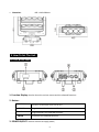
1
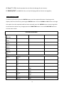
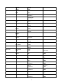
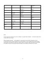
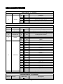
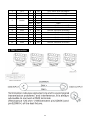
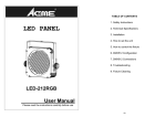
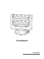
FLEX BEAM K8
User Manual
Please read the instruction carefully before use
1
CONTENTS
1. Safety Instructions ................................................................................................... 3
2. Technical Specifications ........................................................................................... 4
3. How To Set The Unit................................................................................................. 5
3.1 Front & Rear Panel .................................................................................................. 5
3.2 Main Function...................................................................................................... 6
4. How to Control the Unit ........................................................................................... 9
4.1 Master/Slave Built In Preprogrammed Function ................................................. 9
4.2 DMX Address Setting ........................................................................................... 9
5. DMX512 Configuration .......................................................................................... 10
6. DMX Connection .................................................................................................... 11
7. Troubleshooting......................................................................................................... 12
8. Fixture Cleaning ..................................................................................................... 13
2
1. Safety Instructions
Please read the instructions carefully which includes important
information about the installation, operation and
maintenance.
WARNING
• PLEASE keep this User Manual for future consultation. If you sell the fixture to another user,
make sure that they also receive this instruction booklet.
• PLEASE unpack and check carefully there is no transportation damage before using the fixture.
• It’s important to ground the yellow/green conductor to earth in order to avoid electric shock.
• PLEASE disconnect main power before servicing and maintenance.
• Maximum ambient temperature is Ta: 40℃. DO NOT operate it where the temperature is
higher than this.
• Unit’s surface temperature may reach up to 85℃. DO NOT touch the housing bare-handed
during its operation.
• In the event of serious operating problem, stop using the fixture immediately. Never try to
repair the fixture by yourself. Repairs carried out by unskilled people can lead to damage or
malfunction. Please contact the nearest authorized technical assistance center. Always use the
same type spare parts.
• DO NOT connect the device to any dimmer pack.
• DO NOT touch any wire during operation and there might be a hazard of electric shock.
• The housing must be replaced if they are visibly damaged.
Warning
• To prevent or reduce the risk of electrical shock or fire, do not expose the unit to rain or
moisture.
• DO NOT open the unit within five minutes after switching off.
• The housing, the lenses, or the ultraviolet filter must be replaced if they are visibly damaged.
For 230V 50Hz power supply, maximum fixtures that can be connected together from the
same mains outlet is 7pcs;
For 120V 60Hz power supply, maximum fixtures that can be connected together from the
same mains outlet is 4pcs;
3
Caution:
There are no user serviceable parts inside the unit. DO NOT open the housing or attempt any
repairs yourself. In the unlikely event your unit may require service, please contact your nearest
dealer.
Installation:
The unit should be mounted via its screw holes on the bracket. Always ensure that the unit is
firmly fixed to avoid vibration and slipping while operating. And make sure that the structure to
which you are attaching the unit is secure and is able to support a weight of 10 times of the unit’s
weight. Also always use a safety cable that can hold 12 times of the weight of the unit when
installing the fixture.
The equipment must be fixed by professionals. And it must be fixed at a place where is out of the
touch of people and has no one pass by or under it.
2. Technical Specifications
• Innovative moving heads, delivering marvelous, laser-like and long-throw multi-beam effects
• Moving pan with 2 movable LED bars, each with 4 pixel controlled 10W LEDs for the best
mid-air lighting effects
• 3 Operation Modes: DMX, Mater/Slave mode, Sound Activation.
• DMX Channel modes: 1, 7 and 13 channels
• Great built-in programs under master/slave operation triggered by music.
• Smooth dimming and various strobe effects.
• Punch powerful beams, covering whole venue, perfect for events, discos, bars, Mobile DJs and
more.
• Power Voltage:
AC 100~240V, 50/60Hz
• Power Consumption:
90W
• LED Sources:
8 x 10W White LEDs
• Weight:
7.8kgs
4
• Dimension:
405 x 148 x 381mm
3. How To Set The Unit
3.1 Front & Rear Panel
1. Function Display: Used to show the various menus and the selected functions.
2. Button:
FUNCTION
DOWN
UP
ENTER
To return to the upper menu one by one
To go backward in the selected functions
To go forward in the selected functions
To confirm the selected functions
3. POWER IN/OUT: Used to connect to supply power;
5
4. Fuse (T 3.15A): Used to protect the unit from the damage of over-current;
5. DMX IN/OUT: For DMX512 links, use 3-pin XLR plug cable to link the unit together;
3.2 Main Function
To select any functions, press the ENTER button until the required function is showing on the
display. Select the function by pressing the ENTER button. Use the DOWN and UP button to change
the mode. Once the required mode has been selected, press the ENTER button to setup to go back
to the functions without any changes press the FUNCTION button. Press the FUNCTION button to
exit the menu mode.
OPERATION MENU
BEAM-K8
Addr=001
BEAM-K8
A-Auto
BEAM-K8
M-Auto
BEAM-K8
A-Music
BEAM-K8
M-Music
BEAM-K8
Slave
Address
Reset
Manual
Address
=001
Reset
=NO
Reset
=YES
Manual
Pan
Manual
Tilt 1
Manual
Tilt 2
Manual
Dimmer
Pan
=000
Tilt 1
=000
Tilt 2
=000
Dimmer
=000
6
Mode
Manual
Strobe
Mode =
DMX
Mode =
Auto
Mode =
Music
Option
Mode =
Slave
Option
Display
Option
Lost DMX
Advanced
Advanced
Code
Advanced
Adjust
Strobe
=000
DMX Mode
Short
DMX Mode
Standard
DMX Mode
Extended
Auto
Alone
Auto
Master
Music
Alone
Music
Master
Display
DelayOff
Display
Always
Lost DMX
=Clear
Lost DMX
=Hold
Code
=000
Adjust
Pan
Adjust
Tilt 1
Adjust
Tilt 2
Adjust
Dimmer 1
Adjust
Dimmer 2
Adjust
Dimmer 3
Adjust
Dimmer 4
Adjust
Dimmer 5
7
NOTE:008
Pan
=+000
Tili 1
=+000
Tili 2
=+000
Dimmer 1
=+000
Dimmer 2
=+000
Dimmer 3
=+000
Dimmer 4
=+000
Dimmer 5
=+000
View
Default
Advanced
Mic Sens
View
Hours
View
DMX Value
View
Version
Load Def
=NO
Load Def
=YES
Adjust
Dimmer 6
Adjust
Dimmer 7
Adjust
Dimmer 8
Mic Sens
=080%
Hours
=00000 H
Dimmer 6
=+000
Dimmer 7
=+000
Dimmer 8
=+000
Reset H
=NO
Reset H
=YES
CH = 001
DMX= 000
=1.00F
YYYY.MM
Note:
There is only one Projector to be set as a Master in a signal Cable. If Master’s functions used, Please
disable DMX control signal.
When multiple projectors’ work together in synchronous control state, Parameters can be
transmitted from the master projector to the slave projectors such as DMX channel mode, Display
setting status and operation mode (User memory data is included). Before parameters transmitted,
the projector which will send parameters should be set as a Master and others be as Slaves.
8
4. How to Control the Unit
You can operate the unit in three ways:
1. By master/slave built-in preprogram function
2. By DMX controller
No need to turn the unit off when you change the DMX address, as new DMX address setting will
be affected at once. Each time you turn the unit on, it will show “BEAM-K8” on the display. After
that the unit will be ready to receive DMX signal or run the built in programs.
4.1 Master/Slave Built In Preprogrammed Function
By linking the units together in master/slave, the first unit (the master) will control the other units
(the slave) to give an automatic, sound activated, synchronized light show. This function is good
when you want an instant show.
To set the first unit as a master, press the ENTER button to show the MASTER MODE on the display.
To set the unit as a slave, press the ENTER button to show SLAVE MODE on the display.
4.2 DMX Address Setting
To set the DMX address, press the MENU button to show DMX Address on the display. Press the
ENTER button. Use the DOWN and UP button to change the DMX address. Once the address has
been selected, press the ENTER button to setup, to go back to the functions without any change
press the FUNCTION button. Press the FUNCTION button to exit the menu mode.
Please refer to the following diagram to address your DMX512 channel for the first 4 units.
Channel Mode
Unit 1
Unit 2
Unit 3
Unit 4
1 channel
1
2
3
4
7 channels
1
8
15
22
13 channels
1
14
27
40
9
5. DMX512 Configuration
Short Mode ( 1 Channel )
Number Channel
1
SHOW
DMX Value
0
7
8
69
70 - 131
132 - 193
194 - 255
Description
Blackout
Show1 from slow to fast
Show2 from slow to fast
Show3 from slow to fast
Show4 from slow to fast
Standard Mode( 7 Channels )
Number Channel
1
Pan
2
Tilt 1
3
Tilt 2
4
Dimmer All
5
Strobe
6
Led chase
7
Chase speed
DMX Value
0
- 255
0
- 255
0
- 255
0
- 255
0
9
10 - 250
251 - 255
0
7
8
22
23 37
38 52
53 67
68 82
83 97
98 - 112
113 - 127
128 - 142
143 - 157
158 - 172
173 - 187
188 - 202
203 - 217
218 - 232
233 - 247
248 - 255
0
- 255
Description
Pan 0 to 540 degree
Tilt 1 move -30 to 210 degree
Tilt 2 move -30 to 210 degree
All dimmer 0 to 100%
Blackout
Strobe from slow to fast
Open
Blackout
Chase 1
Chase 2
Chase 3
Chase 4
Chase 5
Chase 6
Chase 7
Chase 8
Chase 9
Chase 10
Chase 11
Chase 12
Chase 13
Chase 14
Chase 15
Chase 16
Full on
Speed from slow to fast
Extended Mode( 13 Channels )
Number Channel
1
Pan
DMX Value
0
- 255
Description
Pan 0 to 540 degree
10
2
3
4
Tilt 1
Tilt 2
Dimmer All
5
Strobe
6
7
8
9
10
11
12
13
Led1
Led2
Led3
Led4
Led5
Led6
Led7
Led8
0
0
0
0
10
251
0
0
0
0
0
0
0
0
-
255
255
255
9
250
255
255
255
255
255
255
255
255
255
Tilt 1 move -30 to 210 degree
Tilt 2 move -30 to 210 degree
All dimmer 0 to 100%
Blackout
Strobe from slow to fast
Open
Dimmer LED1 from 0 to 100%
Dimmer LED2 from 0 to 100%
Dimmer LED3 from 0 to 100%
Dimmer LED4 from 0 to 100%
Dimmer LED5 from 0 to 100%
Dimmer LED6 from 0 to 100%
Dimmer LED7 from 0 to 100%
Dimmer LED8 from 0 to 100%
6. DMX Connection
11
1. Connect the fixture together in a “daisy chain” by XLR plug cable from the output of the fixture
to the input of the next fixture. The cable cannot be branched or split to a “Y” cable.
Inadequate or damaged cables, soldered joints or corroded connectors can easily distort the
signal and shut down the system
2. The DMX output and input connectors are pass-through to maintain the DMX circuit when one
of the units’ power is disconnected.
3. At last fixture, the DMX cable has to be terminated with a terminator to reduce signal errors.
Solder a 120-ohm 1/4W resistor between pin 2(DMX-) and pin 3(DMX+) into a 3-pin XLR-plug
and plug it in the DMX-output of the last fixture.
4. Each lighting fixture needs to have an address set to receive the data sent by the controller.
The address number is between 0-511 (usually 0 & 1 are equal to 1).
5. 3 pin XLR connectors are more popular than 5 pins XLR.
3 pin XLR: Pin 1: GND, Pin 2: Negative signal (-), Pin 3: Positive signal (+)
7. Troubleshooting
Following are a few common problems that may occur during operation. Here are some
suggestions for easy troubleshooting:
A. The fixture does not work, no light
1. Check the connection of power and main fuse.
2. Measure the mains voltage on the main connector.
B. Not responding to DMX controller
1. Check DMX connectors, cables to see if link properly.
2. Check the address settings and DMX polarity.
3. If you have intermittent DMX signal problems, check the pins on connectors or on PCB of the
fixture or the previous one.
4. Try to use another DMX controller.
5. Check if the DMX cables run near or run alongside to high voltage cables that may cause
damage or interference to DMX interface circuit.
C. No response to the sound
12
1. Make sure the fixture does not receive DMX signal.
2. Check microphone to see if it is good by tapping the microphone.
D. One of the channels is not working well
1. The stepper motor might be damaged or the cable connected to the PCB is broken.
2. The motor’s drive IC on the PCB might be out of condition.
8. Fixture Cleaning
The cleaning must be carried out periodically to optimize light output. Cleaning frequency depends
on the environment in which the fixture operates: moist, smoky or particularly dirty surrounding can
cause greater accumulation of dirt on the fixture.
• Clean with soft cloth using normal glass cleaning fluid.
• Always dry the parts carefully.
•
Clean the external optics at least every 30 days.
13
NOTE:
------------------------------------------------------------------------------------------------------------------------------------------------------------------------------------------------------------------------------------------------------------------------------------------------------------------------------------------------------------------------------------------------------------------------------------------------------------------------------------------------------------------------------------------------------------------------------------------------------------------------------------------------------------------------------------------------------------------------------------------------14
Innovation, Quality, Performance
15