1
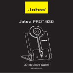
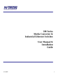
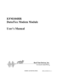
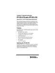
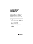
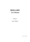
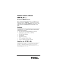
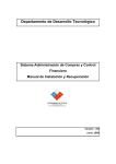
102RAS
Industrial
Remote Access Server
User Manual &
Installation
Guide
Rev 102507
page 1 of 30
Table of Contents
Industrial Remote Access Server Installation Guide .....................................................................................3
General Safety Warnings ...............................................................................................................................4
Environmental Safety.....................................................................................................................................5
Electrical Safety .............................................................................................................................................5
Hazardous Location Installation Requirements .............................................................................................5
Installation......................................................................................................................................................6
DIN Rail Mounting ........................................................................................................................................7
Applying Power (Top View) .........................................................................................................................9
RJ45 CONNECTOR CRIMP SPECIFICATIONS......................................................................................11
Overview of Features...................................................................................................................................12
Troubleshooting ...........................................................................................................................................13
Regulatory Statments ...................................................................................................................................14
Telecom Approvals for the Embedded Modem – Model Number 5634SMI ..............................................16
Software Configuration................................................................................................................................18
Web Management ................................................................................................................................... 18
Web Management - Home ...................................................................................................................... 19
Web Management – Menu Structure ...................................................................................................... 20
Administration – IP Configuration ......................................................................................................... 21
Administration – SMTP Configuration .................................................................................................. 21
Administration – Time Configuration .................................................................................................... 22
Administration – Reset Unit ................................................................................................................... 22
Call Log .................................................................................................................................................. 23
Current Status - System .......................................................................................................................... 24
Current Status – POTS modem 1............................................................................................................ 25
Modem Setup .......................................................................................................................................... 25
Authentication......................................................................................................................................... 26
KEY SPECIFICATIONS.............................................................................................................................28
REGULATORY APPROVALS ..................................................................................................................29
N-TRON Limited Warranty.........................................................................................................................30
Rev 102507
page 2 of 30
Industrial Remote Access Server Installation Guide
102RAS
The N-TRON 102RAS provides connectivity to an industrial LAN for telecommuters or mobile
users, or to remotely installed equipment, via an integrated V.92/56K modem. The small size of the
102RAS makes it ideal for placing alongside other industrial equipment to be accessed remotely.
Product Features
•
•
•
•
•
•
•
•
LAN Port: 10/100BaseT; RJ-45
WAN Port: V92/56K modem; RJ-11
Rates:
Data: V.92/56K downloads and 48K upload speeds from V.92 servers; V.90/56K downloads from
V.90/K56flex servers; 33.6K bps transfers with other servers.
Standards:
Data: V.92, V.90, enhanced V.34 and below
Error Correction: V.42
Data Compression: V.44, V.42bis, MNP Class 5
Security
Local database or RADIUS support
Callback security (local database only)
Redundant Power Inputs (10-30 VDC)
Housed in a ruggedized DIN rail enclosure, designed to withstand the most demanding industrial
applications, and have been fully tested and certified at industrial environmental extremes
Web Browser Configuration
Rev 102507
page 3 of 30
Copyright, © N-Tron Corp., 2006
820 S. University Blvd., Suite 4E
Mobile, AL 36609
USA
All rights reserved. Reproduction, adaptation, or translation without prior written permission from N-Tron
Corp. is prohibited, except as allowed under copyright laws.
Ethernet is a registered trademark of Xerox Corporation. All other product names, company names, logos
or other designations mentioned herein are trademarks of their respective owners.
The information contained in this document is subject to change without notice. N-Tron Corp. makes no
warranty of any kind with regard to this material, including, but not limited to, the implied warranties of
merchantability or fitness for a particular purpose. In no event shall N-Tron Corp. be liable for any
incidental, special, indirect or consequential damages whatsoever included but not limited to lost profits
arising out of errors or omissions in this manual or the information contained herein.
WARNING
Do not perform any services on the unit unless qualified to do so. Do not substitute unauthorized parts or
make unauthorized modifications to the unit.
Do not operate the unit with the top cover removed, as this could create a shock or fire hazard.
Do not block the air vents on the top of the unit.
Do not operate the equipment in the presence of flammable gasses or fumes. Operating electrical equipment
in such an environment constitutes a definite safety hazard.
Do not operate the equipment in a manner not specified by this manual.
General Safety Warnings
WARNING: If the equipment is used in the manner not specified by N-Tron Corp., the protection
provided by the equipment may be impaired.
Contact Information
N-Tron Corp.
820 South University Blvd. Suite 4E
Mobile, AL 36609
TEL: (251) 342-2164
FAX: (251) 342-6353
Website: www.n-tron.com
Email: [email protected]
Rev 102507
page 4 of 30
Environmental Safety
WARNING: Disconnect the power and allow to cool 5 minutes before touching.
Electrical Safety
WARNING: Disconnect the power cable before removing any modules, or any enclosure panel.
WARNING: Do not operate the unit with the cover removed.
WARNING: Do not work on equipment or cables during periods of lightning activity.
WARNING: Do not perform any services on the unit unless qualified to do so.
WARNING: Do not operate the equipment in the presence of flammable gasses or fumes. Operating
electrical equipment in such an environment constitutes a definite safety hazard.
WARNING: Do not block the air vents.
WARNING: Observe proper DC Voltage polarity when installing power input cables. Reversing voltage
polarity can cause permanent damage to the unit and void the warranty.
Hazardous Location Installation Requirements
1. WARNING: Do not remove or replace while circuit is live unless the area is known to be free of
ignitable concentrations of flammable gases or vapors.
2. WARNING: Explosion hazard. Do not disconnect while the circuit is live or unless the area is known
to be free of ignitable concentrations.
3. WARNING: Install only in accordance with Local & National Codes of Authorities Having
Jurisdiction.
4. WARNING: Explosion Hazard - Substitution of components may impair suitability for Class I,
Division 2.
5. Class I, Div 2 Installations require that power connections must be current limited at the power source
with an in-line fuse rated at 0.5A.
6. Class I, Div 2 installations require that all devices connected to this product must be UL listed for the
area in which it is installed.
Rev 102507
page 5 of 30
7. Use 60/75ºC rated Copper wire, (022Nm) 2 inch-lbs Tightening torque for field installed connectors.
8. Limited Operating Voltage: 10-30V for Class I, Div 2 installations.
9. This apparatus is suitable for use in Class I, Div 2, Groups A, B, C, and D, or unclassified or
nonhazardous locations only.
Package Contents
Please make sure the 102RAS Remote Access Server package contains the following items:
1. 102RAS Remote Access Server
2. Product CD
Contact your carrier if any items are damaged.
Installation
Read the following warning before beginning the installation:
WARNING
Never install or work on electrical equipment or cabling during periods of lightning activity. Never connect
or disconnect power when hazardous gasses are present.
Disconnect the power cable before removing any enclosure panel.
Do not operate the unit with any covers removed
Unpacking
Remove all the equipment from the packaging, and store the packaging in a safe place. File any damage
claims with the carrier.
Cleaning
Clean only with a damp cloth.
Rev 102507
page 6 of 30
DIN Rail Mounting
Install the unit on a standard 35mm DIN rail. Recess the unit to allow at least 3” of horizontal clearance for
cable bend radius.
To mount the unit to the 35mm DIN rail,
place top edge of the brackets on the back of the
unit against the DIN rail at a 45° upward angle.
Lower the bottom of the unit until it snaps into
place on each bracket.
To remove the unit from the 35mm DIN rail, typically
it is possible to remove the unit by using your index and
middle fingers or use flat head screwdrivers placed into
each of the release clips at the bottom of the unit to push
down on each clip until they disengage the bottom of the
unit from the DIN rail. Lift the bottom of the unit up at
an approximate 45° upward angle to completely remove
the unit.
Most N-Tron™ products are
designed to be mounted on industry
standard 35mm DIN rail. However,
DIN rail mounting may not be
suitable for all applications. Our Rack
Mount Assembly (P/N: 900-RM)
may be used to mount the 102RAS to
standard 19" racks as an option.
Rev 102507
page 7 of 30
Front Panel
From Top to Bottom:
RJ-45 Port
RJ-11 Port
TR
CD
TX
RX
Green LED lights when Power is supplied to the module
Auto sensing 10/100 Base-TX Connection
Phone line connection
Transmit Ready
Carrier Detect
Transmit
Receive
Note: The RJ45 data port has two LED’s located at the side of the connector. The bottom LED indicates
LINK status, and the top LED indicates ACTIVITY.
LED’s: The table below describes the operating modes:
LED
Description
Lit when Power is applied.
LNK
Lit when 10/100 Mb Link between ports exists.
ACT
Lit when data is active between ports.
TR
Lit when 102RAS modem is ready to answer.
CD
Lit when carrier is detected by 102RAS.
TX
Lit when data is being transmitted by 102RAS.
RX
Lit when data is being received by 102RAS.
Phone Interface
The 102RAS provides an RJ-11 phone line interface to connect to a standard wall outlet.
Rev 102507
page 8 of 30
Applying Power (Top View)
•
•
•
•
•
•
•
Remove Supplied #6 Phillips head grounding screw from top of unit.
Connect ground wire with lug (not supplied) and re-install the grounding screw securely.
Unscrew & Remove the DC Voltage Input Plug from the Power Input Header
Install the DC Power Cables into the Plug (observing polarity).
Plug the Voltage Input Plug back into the Power Input Header.
Tightening torque for the terminal block power plug is 0.22 Nm/0.162 Pound Foot.
Verify the Power LED stays ON (GREEN).
Note: Only 1 power supply must be connected to power for minimal operation. For redundant power
operation, V1 and V2 inputs must be connected to separate DC Voltage sources. This device draws current
from both sources simultaneously. Use 16-28 gauge wire when connecting to the power supply.
Recommended 24V DC Power Supplies, similar to: N-Tron’s P/N NTPS-24-1.3, 24VDC at 1.3A
Rev 102507
page 9 of 30
N-TRON SWITCH GROUNDING TECHNIQUES
The grounding philosophy of any control system is an integral part of the design. N-Tron switches are
designed to be grounded, but the user has been given the flexibility to float the switch when required. The
best noise immunity and emissions (i.e. CE) are obtained when the N-Tron switch chassis is connected to
earth ground via a drain wire. Some N-Tron switches have metal din-rail brackets that can ground the
switch if the din-rail is grounded. In some cases, N-Tron switches with metal brackets can be supplied with
optional plastic brackets if isolation is required.
Both V- legs of the power input connector are connected
to chassis internally on the PCB. Connecting a drain wire
to earth ground from one of the V- terminal plugs as
shown here will ground the switch and the chassis. The
power leads from the power source should be limited to 3
meters or less in length.
As an alternate, users can run a drain wire & lug from any of the DinRail screws or empty PEM nuts on the enclosure. When using an
unused PEM nut to connect a ground lug via a machine screw, care
should be taken to limit the penetration of the outer skin by less than 1/4
in. Failure to do so may cause irreversible damage to the internal
components of the switch.
Note: Before applying power to the grounded switch, you must use a
volt meter to verify there is no voltage difference between the power
supply’s negative output terminal and the switch chassis grounding
point.
The use of shielded cables between devices is not required for most N-Tron devices (please consult the user
manuals for specific details). If the use of shielded cables is required, it is generally recommended to only
connect the shield at one end to prevent ground loops and interfere with low level signals (i.e.
thermocouples, RTD, etc.). Cat5e cables manufactured to EIA-568A or 568B specifications are required for
use with N-Tron Switches.
In the event all Cat5e patch cable distances are small (i.e. All Ethernet devices are located the same local
cabinet and/or referenced to the same earth ground), it is permissible to use fully shielded cables terminated
to chassis ground at both ends in systems void of low level analog signals.
Rev 102507
page 10 of 30
RJ45 CONNECTOR CRIMP SPECIFICATIONS
Please reference the illustration below for your Cat5 cable specifications:
Rev 102507
page 11 of 30
Overview of Features
Compact Remote Access Solution
The 102RAS includes one integrated V.92/56K modem, housed in a compact, industrial chassis which
provides V.92/56K download speeds and 48K upload speeds when connecting with V.92 servers. Dial-in
users can achieve V.34/33.6K connections. Unit ships with 35mm DIN rail connector suitable for mounting
the unit on 35mm DIN rail in industrial environment.
Secure Remote Access
The 102RAS has a built-in security database for user name and password authentication for all remote users.
It also has a built-in RADIUS client for authentication to a RADIUS server.
Callback Security
The 102RAS provides password protection with callback security, and helps reduce long distance charges,
for remote offices and users requiring access to the central site LAN. The 102RAS server supports three
security options. The “fixed” callback option stores a password and the remote user’s phone number. Once
the remote site enters their password, the 102RAS calls back using the number stored in its database. The
“variable” option lets the user enter a fixed password and a variable call back number each time they call.
The “pass through” option is used to provide the security of password protection, while bypassing the call
back process.
Configuration and Management
The 102RAS web interface provides for easy set-up and configuration. In addition, it provides the ability to
view the current line status as well as a history of past activity.
Note: N-Tron does not provide technical support for the below Shared Modem Usage using Third
Party software (N-Tron does not provide any software for this use).
Shared Dial-Out Convenience
The 102RAS can also provide dial-out support for PC users on IP. This means system administrators no
longer have to dedicate a modem for LAN users who need to access information services. When used in
Modem Sharing mode, computers with network access to the 102RAS can use Telnet on port 7000 and get
direct access to the modem in the 102RAS. More commonly a com port redirector can be installed on the
workstation(s). A redirector adds a virtual communication port to Windows and uses Telnet to map
(redirect) the com port to the modem. Communication programs using this virtual com port will have its
data redirected to and from the modem within the 102RAS, eliminating the need for each workstation to
have its own modem and phone line. Only one com port (telnet session) can be open at a time.
Rev 102507
page 12 of 30
Troubleshooting
1.
Make sure the
2.
Make sure you are supplying sufficient current. Note: The Inrush current will exceed the
steady state current by ~ 2X.
3.
Verify that Link LED’s are ON for connected ports.
4.
Verify cabling used between stations.
5.
Verify the phone socket that the phone line from the 102RAS is plugged into is operational.
6.
Verify that cabling is Category 5E or greater for 100Mbit Operation.
(Power LED) is ON.
Support
Contact N-Tron Corp. at:
TEL: 251-342-2164
FAX: 251-342-6353
www.n-tron.com
[email protected]
Rev 102507
page 13 of 30
Regulatory Statements
47 CFR Part 15 Regulation
This device complies with Part 15 of the FCC Rules. Operation is subject to the following two conditions:
(1) this device may not cause harmful interference, and (2) this device must accept any interference
received, including interference that may cause undesired operation.
Industry Canada
This Class A digital apparatus complies with Canadian ICES-003.
Cet appareil numérique de la classe A est conforme à la norme NMB-o003 du Canada.
47 CFR Part 68 Telecom
1. This equipment complies with Part 68 of the 47 CFR rules and the requirements adopted by the
ACTA. Located on this equipment is a label that contains, among other information, the registration
Number and ringer equivalence number (REN) for this equipment or a product identifier in the
format:
For current products is US:AAAEQ##Txxxx.
For legacy products is AU7USA-xxxxx-xx-x.
If requested, this number must be provided to the telephone company.
2. A plug and jack used to connect this equipment to the premises wiring and telephone network must
comply with the applicable 47 CFR Part 68 rules and requirements adopted by the ACTA. It’s
designed to be connected to a compatible modular jack that is also compliant.
3. The ringer equivalence number (REN) is used to determine the number of Devices that may be
connected to a telephone line. Excessive RENs on a telephone line may result in the Devices not
ringing in response to an incoming call. In most but not all areas, the sum of RENs should not
exceed five (5.0). To be certain of the number of Devices that may be connected to a line, as
determined by the total RENs, contact the local telephone company. For products approved after
July 23, 2001, the REN for this product is part of the product identifier that has the format
US:AAAEQ##Txxxx. The digits represented by ## are the REN without a decimal point (e.g., 03 is
a REN of 0.3). For earlier products, the REN is separately shown on the label.
4. If this equipment causes harm to the telephone network, the telephone company will notify you in
advance that temporary discontinuance of service may be required. But if advance notice isn't
practical, the telephone company will notify the customer as soon as possible. Also, you will be
advised of your right to file a complaint with the FCC if you believe it is necessary.
5. The telephone company may make changes in its facilities, equipment, operations or procedures that
could affect the operation of the equipment. If this happens, the telephone company will provide
advance notice in order for you to make necessary modifications to maintain uninterrupted service.
6. If trouble is experienced with this equipment, please contact N-Tron Corp. at the address shown
below for details of how to have the repairs made. If the equipment is causing harm to the telephone
network, the telephone company may request that you disconnect the equipment until the problem is
resolved.
7. Connection to party line service is subject to state tariffs. Contact the state public utility
commission, public service commission or corporation commission for information.
8. No repairs are to be made by you. Repairs are to be made only by N-Tron Corp. or its licensees.
Unauthorized repairs void registration and warranty.
Rev 102507
page 14 of 30
9. If your home or office has specially wired alarm equipment connected to the telephone line, ensure
the installation of this equipment does not disable your alarm equipment. If you have questions
about what will disable alarm equipment, consult your telephone company or a qualified installer.
10. This equipment is hearing aid compatible.
11. Manufacturing Information:
Manufacturer:
N-Tron Corp.
Trade Name:
102RAS
Model Number:
102RAS
Registration No:
AU7USA-25814-M5-E
Ringer Equivalence:
0.3B
Modular Jack (USOC):
RJ11
Service Center in USA:
N-Tron Corp.
820 South University Blvd. Suite 4E
Mobile, AL 36609
U.S.A.
(251) 342-2164
(251) 342-6353 Fax
Canadian Limitations Notice
Notice: The ringer equivalence number (REN) assigned to each terminal Device provides an indication of
the maximum number of terminals allowed to be connected to a telephone interface. The termination on an
interface may consist of any combination of Devices subject only to the requirement that the sum of the
ringer equivalence numbers of all the Devices does not exceed 5.
Notice: The Industry Canada label identifies certified equipment. This certification means that the
equipment meets certain telecommunications network protective, operational, and safety requirements.
The Industry Canada label does not guarantee the equipment will operate to the user’s satisfaction.
Before installing this equipment, users should ensure that it is permissible to be connected to the facilities of
the local telecommunications company. The equipment must also be installed using an acceptable method of
connection. The customer should be aware that compliance with the above conditions may not prevent
degradation of service in some situations. Repairs to certified equipment should be made by an authorized
Canadian maintenance facility designated by the supplier. Any repairs or alterations made by the user to this
equipment or equipment malfunctions may give the telecommunications company cause to request the user
to disconnect the equipment.
Users should ensure for their own protection that the electrical ground connections of the power utility,
telephone lines and internal metallic water pipe system, if present, are connected together. This precaution
may be particularly important in rural areas.
Caution: Users should not attempt to make such connections themselves, but should contact the appropriate
electric inspection authority, or electrician, as appropriate.
New Zealand Telecom Warning Notice
1. The grant of a Telepermit for any item of terminal equipment indicates only that Telecom has accepted
that the item complies with minimum conditions for connection to its network. It indicates no endorsement
of the product by Telecom, nor does it provide any sort of warranty. Above all, it provides no assurance that
any item will work correctly in all respects with another item of Telepermitted equipment of a different
make or model, nor does it imply that any product is compatible with all of Telecom’s network services.
This equipment is not capable under all operating conditions of correct operating conditions of correct
operation at the higher speed which it is designated. 33.6 kbps and 56 kbps connections are likely to be
Rev 102507
page 15 of 30
restricted to lower bit rates when connected to some PSTN implementations. Telecom will accept no
responsibility should difficulties arise in such circumstances.
2. Immediately disconnect this equipment should it become physically damaged, and arrange for its
disposal or repair.
3. This modem shall not be used in any manner which could constitute a nuisance to other Telecom
customers.
4. This device is equipped with pulse dialing, while the Telecom standard is DTMF tone dialing. There is
no guarantee that Telecom lines will always continue to support pulse dialing.
Use of pulse dialing, when this equipment is connected to the same line as other equipment, may give rise to
'bell tinkle' or noise and may also cause a false answer condition. Should such problems occur, the user
should NOT contact the Telecom Faults Service.
The preferred method of dialing is to use DTMF tones, as this is faster than pulse (decadic) dialing and is
readily available on almost all New Zealand telephone exchanges.
5. Warning Notice: No '111' or other calls can be made from this device during a mains power failure.
6. This equipment may not provide for the effective hand-over of a call to another device connected to the
same line.
7. Some parameters required for compliance with Telecom’s Telepermit requirements are dependent on the
equipment (PC) associated with this device. The associated equipment shall be set to operate within the
following limits for compliance with Telecom’s Specifications:
For repeat calls to the same number:
• There shall be no more than 10 call attempts to the same number within any 30 minute period for any
single manual call initiation, and
• The equipment shall go on-hook for a period of not less than 30 seconds between the end of one attempt
and the beginning of the next attempt.
For automatic calls to different numbers:
• The equipment shall be set to ensure that automatic calls to different numbers are spaced such that there is
no less than 5 seconds between the end of one call attempt and the beginning of another.
8. For correct operation, total of the RN’s of all devices connected to a single line at any time should not
exceed 5.
South African Statement
This modem must be used in conjunction with an approved surge protection device.
Telecom Approvals for the Embedded Modem – Model Number 5634SMI
Country
Status
Approval Number
Argentina
Australia
Austria
Belgium
Brazil
Canada
Chile
China
Approved
Approved
Approved
Approved
Approved
Approved
Approved
Approved
CNC 54-4936
ACN092448710
CE
CE
ANATEL 0214-03-1845
125-10317A
SUBTEL 3672
20650004500320
Rev 102507
page 16 of 30
China NALTE
Cyprus
Czech Republic
Denmark
Estonia
Finland
France
Germany
Greece
Hong Kong
Hungary
Iceland
India
Indonesia
Ireland
Israel
Italy
Japan
Korea
Latvia
Liechtenstein
Lithuania
Luxembourg
Malta
Mexico
Netherlands
New Zealand
Norway
Philippines
Poland
Portugal
Russia Telecom
Russia Safety
Singapore
Slovakia
Slovenia
South Africa
Spain
Sweden
Switzerland
Taiwan
Turkey
United Kingdom
United States
Rev 102507
Approved
Approved
Approved
Approved
Approved
Approved
Approved
Approved
Approved
Approved
Approved
Approved
Approved
Approved
Approved
Approved
Approved
Approved
Approved
Approved
Approved
Approved
Approved
Approved
Approved
Approved
Approved
Approved
Approved
Approved
Approved
Approved
Approved
Approved
Approved
Approved
Approved
Approved
Approved
Approved
Approved
Approved
Approved
Approved
10-6066-060989
CE
CE
CE
CE
CE
CE
CE
CE
SL 300063
CE
CE
TEC/NR/I/MOD-08/01/082.JUL03
01144/1/POSTEL/2003
CE
13-12323-0-103246-07/06
CE
AD04-0451001
TE-A22/K012-04-0357
CE
CE
CE
CE
CE
COFETEL:TTDMUMT021-411
CE
PTC 0211/00/095 RN=0.5
CE
ESD-CPE-04000628
CE
CE
д-TOP-0120
Mл05
DB-00626
CE
CE
TE-2002/121
CE
CE
CE
B93-M007-F
AG/UM-2001.235
CE
AU7USA-25814-M5-E REN:03B
page 17 of 30
Software Configuration
Web Management
Enter the switch’s IP address in any web browser and login to the web management feature of the
102RAS.
Default:
Username: admin
Password: admin
Rev 102507
page 18 of 30
Web Management - Home
When the administrator first logs onto the 102RAS, the default home page is displayed. At the top
of the screen there is a list of configurable settings which the 102RAS supports. This section of the manual
will go through each choice listed at the top of the screen and explain how to configure those settings. In
the center of the main home page the administrator/user can see some basic information like what firmware
revision the 102RAS is running.
Rev 102507
page 19 of 30
Web Management – Menu Structure
Home
•
Shows information about the manufacturer and the 102RAS, along with support Website and E-Mail
addresses.
Login
•
Brings up the Login page
Logout
• Logs off the current user
Administration
• IP Configuration
– Shows the current IP Configuration and allows User to change.
• SMTP Configuration – Shows the current SMTP Configuration and allows User to change.
• Time Configuration – Shows the current Time Configuration and allows User to change.
• Reset Unit
– Resets the 102RAS.
Local Users
• Shows information about the Local User Database, and allows User to modify.
Call Log
• Log Parameters
• Call Log
– Shows the current Logging Configuration and allows User to change.
– Shows the Call Log and allows User to select details for any call.
Current Status
• System
• POTS Modem 1
– Shows the status of the 102RAS.
– Shows the status of the embedded Modem.
Modem Setup
• Modem Setup
• General Modem Setup
– Shows the current Modem Configuration and allows User to change.
– Shows the general Modem Configuration and allows User to change.
Authentication
• Authentication Setup – Shows the current Authentication Configuration and allows User to
change.
• Radius Client Setup – Shows the current Radius Client Configuration and allows User to change.
Rev 102507
page 20 of 30
Administration – IP Configuration
The IP Configuration part of the Administration page lists the following information about the 102RAS:
IP Address
Subnet Mask
Default Gateway
Name Server
Secondary Name Server
You may change the values to apply to your network and select the update button to save the values. The
fields for “IP Address”, “Subnet Mask”, “Default Gateway” and “Name Server” are required. A
“Secondary Name Server” is optional.
Administration – SMTP Configuration
The SMTP Configuration part of the Administration page lists the following information about the 102RAS:
SMTP Server Address
SMTP Port
Administrator E-Mail
SMTP Password
From here you can setup the Mail Server by following the following steps:
1) A mail server in the “SMTP Server Address” field.
2) The E-Mail address of the Administrator in the “Administrator E-Mail” field.
3) If the SMTP Server requires a User ID, enter the ID in the “SMTP Server User ID” field.
4) If the SMTP Server requires a password, enter the password in the “SMTP Password” field.
5) If you enter a password, retype the identical password in the “Retype SMTP Password” field
6) Click on Update. At this point the 102RAS will send the Administrator an e-mail saying that the
mail server has been updated.
Rev 102507
page 21 of 30
Administration – Time Configuration
The Time Configuration part of the Administration page lists the following information about the 102RAS:
Time Server
Request Interval
Time Zone
Date Format
Time Format
From here you can set the time configuration used for time stamping on the 102RAS. You can make
modifications then click the update button to save the new configuration.
Note: By default, the 102RAS receives the date and time via Time Server via an internet connection.
In the event the Local LAN (where the 102RAS is installed) does not have access to the internet, you
must enter the IP Address of a Server on the Local LAN that has a Network Time Protocol (NTP)
service enabled in order to have correct date and time recorded in the log.
Administration – Reset Unit
From here the Administrator can remotely reset the 102RAS by clicking on the reset button.
Local Users
This page shows the local database stored on the 102RAS, and lists the following items:
Name
User ID
Password
Callback
Callback#
From here, the Administrator’s Name, User ID and Password can be changed. Also, Local users may be
added by filling out a new row and selecting the add button. Once Local users have been added, a user can
Rev 102507
page 22 of 30
be removed by selecting the delete button and can be updated by changing the information and selecting the
update button.
Callback Security Options:
1) Administrator:
If the Callback Security option is enabled and Admin specified is selected, then enter your fixed
callback telephone number in the Callback # window. If the Callback Security option is enabled and User
Specified is selected, you do not enter a telephone number in the Callback # window. You enter the
callback telephone number during the dial-in process.
2) Remote user:
If you are going to enable the Callback Security option, click on the Callback down arrow and
choose the callback method. A fixed phone number is Admin specified or a variable phone number is User
specified. For example, if a traveling sales person needs to be called back at their current location, they will
provide the callback telephone number during the dial-in process.
If the Callback Security option is enabled and Admin specified is selected, then enter their fixed
callback telephone number in the Callback # window. If the Callback Security option is enabled and User
specified is selected, you do not enter a telephone in the callback # window. The remote user enters the
callback number during the dial-in process.
Note: The first row is for the “Administrator” function. No matter what values are used for the Name,
User ID and Password fields, the first row will apply to the person doing the Administrator function
for the 102RAS. The Administrator is the party privileged to configure the 102RAS.
Call Log
The Call Log screen displays the parameters you can set for the Call Log entries and displays a call log
entry for each call.
The Log Parameters define the threshold number of entries and the number of entries retained in the log
history. Both Auto Log Threshold and Log History can be set to a maximum of 20 entries by filling in the
field and clicking on Save Changes. The log can be E-Mailed to the Administrator address by clicking on
Send Log Now and the Log can be deleted by clicking on Delete Log.
The Call Log summarizes each call and the Details button displays an in-depth look at the call from the
individual initiating the call, when the call was connected, duration of the call, transmit and receive baud
rates, to authentication status.
Rev 102507
page 23 of 30
Current Status - System
This page shows the Current System Status of the 102RAS and shows the following values:
Current Time
Up Time
Pending Messages
Email Status
Email To
Subject
Time Server Status
Current Time
Pending Messages
Email To
Subject
Time Server Status
Up Time
E-mail Status
- Indicates the present time of day.
- Indicates the number of e-mails sent to the administrator that have not been opened.
These can include debug log messages, mail server change notification messages.
(relating to the “SMTP Server Address” field of Administration screen).
- Indicates the Administrator’s address to which e-mails should be sent.
- Title of the last pending or sent e-mail.
- Indicates the status of the Time server which could be “Initializing”, “No Errors”, or
SNTP Error: type.
- Operation time since last reboot.
- Indicates whether the 102RAS e-mail transmissions, both calls and administrative
messages, are proceeding with or without errors, may be one of the following.
“No Errors”, “Bad MailServer Address”, “Mail Server Connect Failed”,
“SMTP Invalid Response”, “SMTP Client Timeout”.
Note: The 102RAS synchronizes its call time stamps to an Internet source, usually a government standards
site. It will attempt contact with the standards web site 5 times in 20 seconds. If contact fails, it will
try 5 times again 5 minutes later. If contact succeeds, the 102RAS will update its stamping time
periodically per an interval set in the Administration screen.
Rev 102507
page 24 of 30
Current Status – POTS modem 1
This page shows the Current Status of the POTS Modem embedded in the 102RAS.
State
Connect Time
Elapsed Time
State
- Indicates the modem’s current operating condition which can be one of the following:
“Waiting for Ring”, “Initializing Modem”, “Waiting for Connect”, “User login”,
“Getting Call Info”.
Connect Time - The date and time at which the connection began for the current call.
Elapsed Time - The duration of the current call in seconds.
The Administrator can also initialize the modem by clicking on Initialize Modem, or make the modem go
off hook by clicking on Make Busy.
Modem Setup
This page shows the current Modem configuration of the 102RAS.
Modem Usage
Country Code
Number of rings to answer on
If you are using the 102RAS for dial-in PPP access (default usage), you do not have to modify the modem
usage, but you do have to select the Country Code.
Rev 102507
page 25 of 30
Note: The following modem sharing options are available, but N-Tron does not provide technical
support for using third party software with the 102RAS (N-Tron also does not provide any
software for this use).
If you are using your 102RAS for dial-out, you will have to select one of the Modem Sharing options and
select the Country Code. With any of the Modem Sharing options, the TCP port number used to access the
modem is 7000. Modem Sharing with authentication means a login prompt will be issued to the socket
when it is opened. The opener of the socket must provide appropriate credentials before access is given to
the modem. If RAW is also selected – support for RFC 2217 (com port control vial Telnet) will be disabled.
Modem Sharing – No Authentication - Immediate access is given to the modem.
Modem Sharing – Local Authentication - A valid set of credentials, defined in the Local User data base,
is required before access is granted.
Modem Sharing – Radius Authentication - A valid set of credentials, defined in the Radius User data
base, is required before access is granted.
Modem Sharing – Raw Mode with No Authentication - User data is treated “as is”, without
interpretation, and no authentication is required.
Modem Sharing – Raw Mode with Local Authentication - User data is treated “as is”, without
interpretation, and a valid set of credentials, defined in the Local User data base, is required before access is
granted.
Modem Sharing – Raw Mode with Radius Authentication - User data is treated “as is”, without
interpretation, and a set of credentials, defined in the Radius User data base, is required before access is
granted.
Caution: Modem sharing is accomplished by implementing a Telnet interface to the 102RAS’s embedded
modem. Secure the access to the port via a firewall or IP filter settings to prevent unauthorized use of your
modem resource.
Authentication
This page shows the current Authentication configuration of the 102RAS.
Authentication Setup
Remote Host Address
Radius Server Address 1 and Port
Radius Accounting Address 1 and Port
Secret
If your database for user credentials resides in the Local User Database on the 102RAS, then accept the
default – “local”. If your user database resides on a Radius Server, then click on the down arrow and choose
radius.
If modem usage is RAS, enter a static IP Address in the Remote Host Address window which will be
assigned to the dial-in user. This Remote Host Address has to match the network scheme of the 102RAS.
Rev 102507
page 26 of 30
If you are setting up the 102RAS to use Radius authentication, then:
1) Enter the IP address of the primary RADIUS Server in the RADIUS Server Address 1 field.
2) Enter the port number (usually port 1812) for the RADIUS Server in the top Port field.
3) Enter the IP address of the Radius Accounting server in the RADIUS Accounting Address 1 field.
4) Enter the port number (usually port 1813) for the Radius Accounting Server in the bottom Port field.
5) Enter the Secret of the Radius Server that you are communicating with. The Secret has to be
identical to the one used by your Radius Server.
Rev 102507
page 27 of 30
KEY SPECIFICATIONS
Physical
Height:
3.40" (8.64cm)
Width:
1.50" (3.81 cm)
Depth:
3.60" (9.14 cm)
Including DIN-Rail Mount:4.32” (10.9 cm)
Weight:
0.70 lbs (0.32 kg)
DIN-Rail:
35mm
Electrical
Redundant Input Voltage:
Input Current:
Inrush Current:
Input Ripple:
10-30 VDC (Regulated)
221 mA at 24VDC (Steady State)
7.4 A /0.7 ms at 24VDC
Less than 100 mV
Environmental
Operating Temp:
Storage Temp:
Operating Humidity:
Operating Altitude:
-20°C to 70°C
-40°C to 85°C
10% to 95% (Non Condensing)
0 to 10,000 ft.
Shock and Vibration (bulkhead mounting)
Shock:
200g @ 10ms
Vibration/Seismic:
50g, 5-200Hz, Triaxial
Reliability
MTBF:
>1Million Hours
Network Media
10BaseT:
100BaseTX:
>Cat3 Cable
>Cat5 Cable
Connectors
10/100BaseTX:
Phone Line:
One (1) RJ-45 TX Copper Port
One (1) RJ-11 Modular Port
Modem Port
V.92/56K Modem
Data: V.92, V.90, enhanced V.34 & below
Error Correction: V.42
Data Compression: V.44, MNP Class 5; V.42bis
Recommended Wiring Clearance:
Front:
2" (5.08 cm)
Top:
3" (7.62 cm)
Side:
1” (2.54 cm)
Rev 102507
page 28 of 30
REGULATORY APPROVALS
SAFETY: UL Listed in accordance with ANSI/ISA-12.12.01-2000 (US and Canada)
This apparatus is suitable for use in Class I, Div 2, Groups A, B, C, and D, T5
EMI: EN 55022: 1998 w/A1 & A2, CISPR 22 - Class A
47 CFR, Part 15, Subpart B - Class A
47 CFR, Part 68 (Embedded Device – Multi-Tech Systems Model: MT5634SMI)
EMS: EN 55024: 1998 w/A1 & A2
IEC 61000-4-2 Ed. 1.2 (ESD)
IEC 61000-4-3 Ed. 2.1 (RS)
IEC 61000-4-4 2nd Ed. (EFT)
IEC 61000-4-5 2nd Ed. (Surge)
IEC 61000-4-6 Ed. 2.1 (Conducted Disturbances)
GOST-R Certified.
Rev 102507
page 29 of 30
N-TRON Limited Warranty
N-TRON, Corp. warrants to the end user that this hardware product will be free from defects in workmanship and materials,
under normal use and service, for the applicable warranty period from the date of purchase from N-TRON or its authorized
reseller. If a product does not operate as warranted during the applicable warranty period, N-TRON shall, at its option and
expense, repair the defective product or part, deliver to customer an equivalent product or part to replace the defective item,
or refund to customer the purchase price paid for the defective product. All products that are replaced will become the
property of N-TRON. Replacement products may be new or reconditioned. Any replaced or repaired product or part has a
ninety (90) day warranty or the remainder of the initial warranty period, whichever is longer. N-TRON shall not be
responsible for any custom software or firmware, configuration information, or memory data of customer contained in, stored
on, or integrated with any products returned to N-TRON pursuant to any warranty.
OBTAINING WARRANTY SERVICE: Customer must contact N-TRON within the applicable warranty period to obtain
warranty service authorization. Dated proof of purchase from N-TRON or its authorized reseller may be required. Products
returned to N-TRON must be pre-authorized by N-TRON with a Return Material Authorization (RMA) number marked on
the outside of the package, and sent prepaid and packaged appropriately for safe shipment. Responsibility for loss or damage
does not transfer to N-TRON until the returned item is received by N-TRON. The repaired or replaced item will be shipped
to the customer, at N-TRON’s expense, not later than thirty (30) days after N-TRON receives the product. N-TRON shall
not be responsible for any software, firmware, information, or memory data of customer contained in, stored on, or integrated
with any products returned to N-TRON for repair, whether under warranty or not.
ADVANCE REPLACEMENT OPTION: Upon registration, this product qualifies for advance replacement. A replacement
product will be shipped within three (3) days after verification by N-TRON that the product is considered defective. The
shipment of advance replacement products is subject to local legal requirements and may not be available in all locations.
When an advance replacement is provided and customer fails to return the original product to N-TRON within fifteen (15)
days after shipment of the replacement, N-TRON will charge customer for the replacement product, at list price.
WARRANTIES EXCLUSIVE: IF AN N-TRON PRODUCT DOES NOT OPERATE AS WARRANTED ABOVE,
CUSTOMER'S SOLE REMEDY FOR BREACH OF THAT WARRANTY SHALL BE REPAIR, REPLACEMENT, OR
REFUND OF THE PURCHASE PRICE PAID, AT N-TRON'S OPTION. TO THE FULL EXTENT ALLOWED BY LAW,
THE FOREGOING WARRANTIES AND REMEDIES ARE EXCLUSIVE AND ARE IN LIEU OF ALL OTHER
WARRANTIES, TERMS, OR CONDITIONS, EXPRESS OR IMPLIED, EITHER IN FACT OR BY OPERATION OF
LAW, STATUTORY OR OTHERWISE, INCLUDING WARRANTIES, TERMS, OR CONDITIONS OF
MERCHANTABILITY,
FITNESS
FOR
A
PARTICULAR
PURPOSE,
SATISFACTORY
QUALITY,
CORRESPONDENCE WITH DESCRIPTION, AND NON-INFRINGEMENT, ALL OF WHICH ARE EXPRESSLY
DISCLAIMED. N-TRON NEITHER ASSUMES NOR AUTHORIZES ANY OTHER PERSON TO ASSUME FOR IT
ANY OTHER LIABILITY IN CONNECTION WITH THE SALE, INSTALLATION, MAINTENANCE OR USE OF ITS
PRODUCTS. N-TRON SHALL NOT BE LIABLE UNDER THIS WARRANTY IF ITS TESTING AND EXAMINATION
DISCLOSE THAT THE ALLEGED DEFECT OR MALFUNCTION IN THE PRODUCT DOES NOT EXIST OR WAS
CAUSED BY CUSTOMER'S OR ANY THIRD PERSON'S MISUSE, NEGLECT, IMPROPER INSTALLATION OR
TESTING, UNAUTHORIZED ATTEMPTS TO OPEN, REPAIR OR MODIFY THE PRODUCT, OR ANY OTHER
CAUSE BEYOND THE RANGE OF THE INTENDED USE, OR BY ACCIDENT, FIRE, LIGHTNING, POWER CUTS
OR OUTAGES, OTHER HAZARDS, OR ACTS OF GOD.
LIMITATION OF LIABILITY: TO THE FULL EXTENT ALLOWED BY LAW, N-TRON ALSO EXCLUDES FOR
ITSELF AND ITS SUPPLIERS ANY LIABILITY, WHETHER BASED IN CONTRACT OR TORT (INCLUDING
NEGLIGENCE), FOR INCIDENTAL, CONSEQUENTIAL, INDIRECT, SPECIAL, OR PUNITIVE DAMAGES OF ANY
KIND, OR FOR LOSS OF REVENUE OR PROFITS, LOSS OF BUSINESS, LOSS OF INFORMATION OR DATA, OR
OTHER FINANCIAL LOSS ARISING OUT OF OR IN CONNECTION WITH THE SALE, INSTALLATION,
MAINTENANCE, USE, PERFORMANCE, FAILURE, OR INTERRUPTION OF ITS PRODUCTS, EVEN IF N-TRON
OR ITS AUTHORIZED RESELLER HAS BEEN ADVISED OF THE POSSIBILITY OF SUCH DAMAGES, AND
LIMITS ITS LIABILITY TO REPAIR, REPLACEMENT, OR REFUND OF THE PURCHASE PRICE PAID, AT NTRON'S OPTION. THIS DISCLAIMER OF LIABILITY FOR DAMAGES WILL NOT BE AFFECTED IF ANY
REMEDY PROVIDED HEREIN SHALL FAIL OF ITS ESSENTIAL PURPOSE.
DISCLAIMER: Some countries, states, or provinces do not allow the exclusion or limitation of implied warranties or the
limitation of incidental or consequential damages for certain products supplied to consumers, or the limitation of liability for
personal injury, so the above limitations and exclusions may be limited in their application to you. When the implied
warranties are not allowed to be excluded in their entirety, they will be limited to the duration of the applicable written
warranty. This warranty gives you specific legal rights which may vary depending on local law.
GOVERNING LAW: This Limited Warranty shall be governed by the laws of the State of Alabama, U.S.A.
Rev 102507
page 30 of 30