1
LB-OE
Rev. E
1 Product overview
The Flashlink LB-OE is an optical to electrical converter module providing high
performance media conversion for analogue signals with bandwidth from 950 to 2150
MHz. This state of the art unit offers a high sensitivity PIN diode technology followed by
amplifiers with low noise, low distortion and capable of amplifying large signal levels.
The attenuator is a high performance digitally controlled device, giving low distortion
and flat frequency response. The LB-OE is therefore the first choice for all optical
transport demands on L-band.
The LB-OE together with LB-EO, can transport all L-band signals between 950 and
2150 MHz over large distances using fiber optical transport media. The optical input
comes with a sophisticated wideband PIN diode with a sensitivity typically better than –
20dBm operating in the 2nd and 3rd optical windows. The open system platform of
Network Electronics Flashlink system allows easy interoperability with third party fiber
optical systems.
There is also an attenuated monitor output for test and service purposes as well as a
remote control interface.
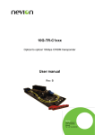
Figure 1: LB-OE L-band O/E converter.
This L-band link is normally used in conjunction with other equipment like satellite
tuners, LNBs in parabolic dishes etc, and the link performance is dependant of good
signal to noise ratio from the signal source and good noise figure of the receiver
equipment. The link quality is also dependant of the number of channels transferred on
the link. For instance, the link’s signal to noise ratio is reduced with 3dB when doubling
the number of the channels (twice the power).
An optical link will add some noise to the signal. The amount of noise is dependant of
the fiber loss, the satellite receiver sensitivity, number of channels and the total power
level of the signal. The combination if analogue and digital satellite signals is also
important. Many analogue satellite signals (which tend to have higher power), will
reduce the signal to noise ratio on the digital signals. This is because the link’s power
must be reduced according to the total power of the link.
Noise figure of the link is a number usually in dB that states how much the signal to
noise ratio (S/N ratio) is reduced from the input to the output. If the S/N ratio from the
dish is X dB, the noise figure on the link is Y dB, the S/N ratio on the output will be X-Y
dB. Dependant on the application (fiber loss, total power on signal and power of the
laser), one link will typically add 4-5dB noise for fiber distances less than 3000 meters.
A coaxial cable will attenuate more on higher frequencies than lower. If the attenuation
on 2GHz is more than the noise figure for the L-band link, there will be a system
nevion.com | 4