1
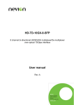
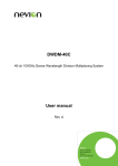
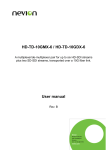
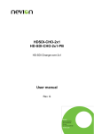
FR-2RU-10-2 Flashlink 2RU frame User manual Rev. N Nevion Nordre Kullerød 1 3241 Sandefjord Norway Tel: +47 33 48 99 99 nevion.com FR-2RU-10-2 Rev. N Nevion Support Nevion Europe Nevion USA P.O. Box 1020 3204 Sandefjord, Norway Support phone 1: +47 33 48 99 97 Support phone 2: +47 90 60 99 99 1600 Emerson Avenue Oxnard, CA 93033, USA Toll free North America: (866) 515-0811 Outside North America: +1 (805) 2478560 E-mail: [email protected] See http://www.nevion.com/support/ for service hours for customer support globally. Revision history Current revision of this document is the uppermost in the table below. Rev. Repl. Date Sign N 12 2015-05-15 MB 12 11 10 11 10 9 2012-02-08 2010-11-08 2010-04-23 JRW TØ TØ 9 8 2008-07-03 RS 8 7 2007-10-26 RS 7 6 2007-09-12 RS 6 5 5 4 2005-04-27 2003-05-07 NBS RS 4 3 2003-03-25 RS 3 2 2 1 2002-04-12 2001-07-10 NBS NBS 1 0 2000-12-21 RS 0 - 2000-12-15 RS Change description Cover page update; DoC removed; no other changes to content Updated Declaration of Conformity Updated Declaration of Conformity Added chapter 2.4 on power consumption. Added text on hot air exhaust, new company address New front page and removed old logo. Added Materials Declaration and EFUP; updated EC Declaration of Conformity. Re-arranged and corrected Chapters, etc. Included the control protocol Corrected printing errors in Chapter 2.1, added GPI information and product designations, shortened fiber optics chapter. Corrected Figure 6 (Chapter 3.4). Changed AURORA to GYDA New laser classification, new silk screen on connector module (fig. 2), corrected address setting of sub-rack module (swapped 0 and 1 in fig. 6) Initial release nevion.com | 2 FR-2RU-10-2 Rev. N Contents Nevion Support ............................................................................................................. 2 Revision history ............................................................................................................ 2 1 Product overview ....................................................................................................... 4 2 Specifications............................................................................................................. 5 2.1 General specifications ............................................................................................. 5 2.2 Front view ............................................................................................................... 5 2.3 Rear view ................................................................................................................ 5 2.4 Power consumption ................................................................................................ 6 3 Configuration ............................................................................................................. 7 3.1 Address setting on each sub-rack ........................................................................... 7 4 Connections ............................................................................................................... 8 4.1 Power connection ................................................................................................... 8 4.1.1 Pin-out DC1 and DC2 (DB9) 8 4.1.2 GPI Power Supply Status outputs 8 4.2 RS-422 connection ................................................................................................. 9 4.2.1 Pin-out RS-422 (RJ45) 9 4.2.2 Connecting several sub-racks together 9 5 Sub-rack operation................................................................................................... 11 5.1 Removing the front panel ...................................................................................... 11 5.2 Back plane insertion.............................................................................................. 12 5.3 Card insertion ....................................................................................................... 14 5.4 Card removal ........................................................................................................ 16 5.5 Adding new module cards ..................................................................................... 17 5.6 Attaching the front panel ....................................................................................... 18 6 Fiber optics .............................................................................................................. 20 6.1 Handling of optical fibres ....................................................................................... 20 6.2 Fiber-optic Connector ........................................................................................... 21 6.3 Laser safety precautions ....................................................................................... 22 7 Flashlink control protocol ......................................................................................... 23 7.1 Document conventions ......................................................................................... 23 7.2 Hardware interface................................................................................................ 23 7.3 Addressing ............................................................................................................ 23 7.4 General command structure .................................................................................. 23 7.5 Card detection (hot swap) ..................................................................................... 24 7.6 Hello command ..................................................................................................... 24 7.7 Electrical to optical converters............................................................................... 24 7.7.1 Hello command 24 7.7.2 Info command 24 7.8 Optical to electrical converters .............................................................................. 25 7.8.1 Hello command 25 7.8.2 Info command 25 General environmental requirements for Flashlink equipment ..................................... 26 Product Warranty ........................................................................................................ 27 Materials declaration and recycling information........................................................... 28 nevion.com | 3 FR-2RU-10-2 Rev. N 1. Product overview The FR-2RU-10-2, hereafter called "sub-rack", is a compact sub-rack frame, providing space for up to 10 Flashlink modules of any combination, in addition to two fixed positions for power supply modules. The sub-rack features maximum flexibility as every module comes with a suitable backplane module, which takes up n x 7TE spacing. This means that any combination of all modules can be fitted into the sub-rack, or expanded / rebuilt in the future, when other functionality is needed. Each sub-rack has an address setting available through DIPswitches on the rear, for use in combination with the GYDA-SC System Controller card. The Flashlink system is built on a low-power consumption philosophy where no fans are needed. This saves the user from fan replacements, fan cleaning and fan filter kits. Power consumption The current draw in the Flashlink frame is limited by the power supplies. Overloading the power supplies will cause the power units to malfunction. Please read chapter 2.4 for further details! Heat dissipation The heat dissipation is based on convection, and it is therefore very important not to block the warm air exhaust on the top. Our guideline is that for every 200W of dissipated power, 1RU of open rack space is needed above the uppermost frame for hot air exhaust. nevion.com | 4 FR-2RU-10-2 Rev. N 2. Specifications 2.1 General specifications AC Power: DC Power (optional): Redundant Power (optional): Dimensions: Card slots: Power Supply slots (reserved): Internal voltages: PWR-AC15/15/5/5V AC power supply module 100-260 VAC. PWR-DC15/15/5/5V DC power supply module 36-72 VDC. PWR-AC15/15/5/5V or PWR-DC15/15/5/5V. 483 x 88 x 178 mm (19”, 2RU). 10. 2. +5V, -5V, +15V, -15V. 2.2 Front view The front view of the sub-rack shows status LEDs for each module that is included in the sub-rack + two green LEDs for the power supply modules. Figure 1: LEDs in front of the Flashlink sub-rack. The uppermost LED of each module card is a "general status" LED. - Green light means that the card is OK. - Red light means that the card is faulty. - No light means that the power is not switched on. The meaning of each LED on the module cards is described in their respective manuals. 2.3 Rear view Figure 2 shows an example of a fully equipped Flashlink sub-rack, seen from the rear side. To the left is the connector module for the power supply delivered with the sub-rack. The other connector modules are described in their respective user manuals. Figure 2: Example of fully equipped Flashlink sub-rack. nevion.com | 5 FR-2RU-10-2 Rev. N 2.4 Power consumption The current draw in the Flashlink frame is limited by the power supplies. Overloading the power supplies will cause the power units to malfunction. The maximum power limits are as followed: Flashlink frame with the PSU 16653 PWR-AC-75W: +5V 45W +15V 15W -15V 15W Flashlink frame with the PSU 11374 PWR-AC15/15/5/5V: +5V 30W +15V 15W -15V 15W The sum of power for all cards on each rail must not be higher than the above listed limits. The power consumption for each of the power supply rails is found in the user manual for each Flashlink card, as this is not the same for all Flashlink cards. The power supplies do not support load sharing. Hence, a second PSU in the frame does not increase the maximum power limits for the system. nevion.com | 6 FR-2RU-10-2 Rev. N 3. Configuration 3.1 Address setting on each sub-rack Each sub-rack can be assigned an address through the DIP-switches on the rear. Maximum 8 sub-rack addresses are available. This address setting only applies when the sub-rack is used in combination with a GYDA-SC Rack System Controller. If you have more than 8 sub-racks together, you need several GYDA-SC Rack System Controller cards. In order to ensure proper operation of the system, it is important that no sub-racks controlled by the same GYDA-SC Rack System Controller card have the same address set. Reset the sub-rack after reconfiguring the sub-rack system, by turning the power off and on again. The setting of the address of a sub-rack is as follows: 1 0 0 means switch to the right (OFF) 1 means switch to the left (ON) SW 4 OFF OFF OFF OFF ON ON ON ON SW 2 OFF OFF ON ON OFF OFF ON ON SW 1 OFF ON OFF ON OFF ON OFF ON Address 0 1 2 3 4 5 6 7 Default address is 0. The GYDA-SC Rack System Controller automatically detects the position of the cards within each sub-rack. More detailed information on the RS-422 configuration can be found in a separate document and at our web site: http://www.nevion.com/ nevion.com | 7 FR-2RU-10-2 4 Rev. N Connections 4.1 Power connection Figure 3 shows the power connections of the sub-rack as well as the RS-422 connections and the DIP-switches for address setting of the sub-rack. Figure 3: Connector module for the power supply. AC: Connect mains to the sub-rack with a mains cord with an IEC 320 connector. DC: Connect the DB9 male connector from the external DC power supply to the main unit. Tighten the screws to ensure a proper contact. The DC inputs have the same function; the left input (DC1) is for the left power module when seen from the rear and DC2 is for the right power module when seen from the rear. 4.1.1 Pin-out DC1 and DC2 (DB9) The maximum current drawn from each pin of the DB9 connector is 2,5A. Pin #1 Pin #2 Pin #3 Pin #4 Pin #5 Pin #6 Pin #7 Pin #8 Pin #9 GND for DC +5V Relay +15V Positive part of 48VDC supply -5V Relay -15V Negative part of 48VDC supply Output, Max. current: 6A GPI Output, Normally Open Output, Max. current: 1A Input Output, Max. current: 1A GPI Output, Normally Open Output, Max. current: 1A Input Pin 1, 2, 4, 6 and 8 are common to both DC1 and DC2. (I.e. they are physically connected). A green LED will light on the front when the power supply is in operation. 4.1.2 GPI Power Supply Status outputs The GPI module status outputs can be used for wiring up alarms for third party control systems. nevion.com | 8 FR-2RU-10-2 Rev. N In case of power failure, pins 3 and 7 will be physically connected (low impedance), otherwise the connection between pins 3 and 7 will be high impedance. 4.2 RS-422 connection At the rear end of the sub-rack is an RS-422 bus. When used in combination with the GYDA-SC Rack System Controller, up to 8 sub-racks can be controlled. On the rear end of the sub-rack are DIP-switches where each sub-rack can be assigned its own address (see figure 3). The RS-422 interfaces are shown in figure 3. 4.2.1 Pin-out RS-422 (RJ45) Pin #1 Pin #2 Pin #3 Pin #4 Pin #5 Pin #6 Pin #7 Pin #8 Rx A (+) Rx B (-) Tx A (+) Reserved Reserved Tx B (-) Not Connected Not Connected Figure 4: RS-422 pin-out. 4.2.2 Connecting several sub-racks together Several sub-racks can be connected to each other through the RS-422 ports on the rear of each sub-rack. One GYDA-SC controller can control maximum 8 sub-racks. You start with the sub-rack containing the GYDA-SC Rack System Controller, and use 1 RS-422 port to loop through to the next. The last sub-rack connected must be terminated with 110 in order to ensure proper operation. The other port of the rack containing the GYDA-SC controller must be left open, and cannot be connected to other sub-racks. Figure 5 shows an example of how to connect 8 sub-racks together as seen from the rear end. By using the RS-422 interface at the GYDA-SC controller card, we control 8 sub-racks via one RS-422 bus. nevion.com | 9 FR-2RU-10-2 Rev. N Figure 5: Control of 8 sub-racks with GYDA-SC. The 110 termination plug used is a standard RJ45 plug with the following internal wiring: 1236 Figure 6: RS-422 termination. In the figure above, Pin 1 is connected to Pin 2 with a 110 resistor, and Pin 3 is connected to Pin 6 with a 110 resistor. nevion.com | 10 FR-2RU-10-2 5 Rev. N Sub-rack operation In order to reconfigure or expand the number of modules within a sub-rack, the front panel must be removed. Each module has a corresponding connector module at the rear, and is hot swappable. Use safety goggles when hot-swapping module cards. If a receiver card is removed from the sub-rack, an invisible laser beam may be emitted inside the sub-rack from the laser at the other end. The laser beam might be harmful to your eyes. 5.1 Removing the front panel Detach the front panel by putting your fingers on the right hand side of the front panel and pull gently, as shown in the figures below. Then pull the front panel slightly to the right before removing it. Hold here "Left circle" Pull here "Right circle" Figure 7: Removing the front panel. A more detailed description of how the front panel is detached is given in figure 8. Step 1 looks at the details in the "right circle" seen from the right hand side, whereas the next two steps (step 2 and step 3) gives the details of the "left circle" as seen from the top. nevion.com | 11 FR-2RU-10-2 Rev. N Figure 8: Removing the front panel (continued). 5.2 Back plane insertion You must install the accompanying back plane card before you can insert a new module card into the frame. Switch off the power with the power switch on the power-supply modules. The green light on the power module is now switched off. If the power supply is redundant, make sure that both power supplies are off. Remove the Flashlink module card from the card slot, according to the procedure in Chapter 5.4. Also remove any card in the position to the right (seen from the front of the frame). Please follow anti-static procedures when handling circuit boards with active components. nevion.com | 12 FR-2RU-10-2 Rev. N Remove all 4 screws (2 screws if a blind back plane is mounted) from the back plane to be replaced. Remove the back plane by lifting it straight out from the rear of the frame. Remove the screws on the back plane to the left of where the new back plane is to be installed (seen from the back of the frame). Lift the right hand side of it slightly. Insert the new back plane. Carefully place the right hand-side of the back plane into the slot first (this is the side without the EMC shielding.) Then, use your business card (or another suitable card), and insert the left edge of the back plane as shown in Figure 9 below. This will help avoid is damage to the EMC shield when inserting the new back plane. Figure 9: Inserting a new back plane. Downward Pressure Figure 10: Inserting a new back plane (continued). Before tightening the screws, use one of your fingers to force the back plane to the bottom of the frame as shown in Figure 10. Tighten the 2 screws at the bottom of the back plane first. This is to avoid mismatch between the connector on the back plane and the PCB. Follow this procedure also for the back plane to the left. nevion.com | 13 FR-2RU-10-2 Rev. N 5.3 Card insertion After the front panel is removed, full access to the card modules inside the sub-rack is given. Switch off the power with the power switch on the power-supply modules. The green light on the power module is now switched off. If the power supply is redundant, make sure that both power supplies are off. The sub-racks are equipped with plastic guide rails to align the module cards into their respective positions 1 to 10. Just before the cards are inserted one should remove the plastic cap from the fiber ferrule as shown in figure 11. Do not touch the ferrule tip with your fingers (see chapter 6.2 - fig. 21). Figure 11: Removal of plastic cap Figure 12: Overview of card positions inside a sub-rack Be careful when inserting the card into the sub-rack. The ferrule of the fiber may be damaged if it touches the sub-rack walls. Do not touch the ferrule tip with your fingers. nevion.com | 14 FR-2RU-10-2 Rev. N Figure 13: Inserting module cards Slide the card into the plastic guide rails inside the sub-rack until the red handle is close to the sub-rack front. A detailed description of the last part of the insertion process is shown in figure 14. Figure 14: Inserting module cards (continued) On the top of the rack is a hole above each module slot. When the tip of the handle is just below this hole (fig. 14 a)), start to bend the handle downwards as in figure 14. The tip of the handle enters the hole and the card is locked and proper contact ensured when the handle is in upright position (fig 14 b). Make sure that the connector on the module card fits with the connector on the back plane card when inserting a new module card for the first time. It should not be necessary to use any force when entering the module card into the accompanying back plane connector. nevion.com | 15 FR-2RU-10-2 Rev. N 5.4 Card removal To remove a module card from the sub-rack frame, release the card by moving the red handle until it is in horizontal position see figure 15 a). Then pull the card out of the sub-rack with the red handle (figure 15 b). After removing a card, it is important that the protective cap is put back on the ferrule tip (figure 15 c) and d). When removing a receiver card from the sub-rack (hot swapping), the laser beam may be present inside the sub-rack (transmitted through the fiber). To avoid damaging your eyes, never look directly into the sub-rack unless you are 100,0 % sure that no laser beam is present inside the sub-rack. Figure 15: Removal of module card. nevion.com | 16 FR-2RU-10-2 Rev. N 5.5 Adding new module cards Figure 16: Overview of rear end of sub-rack showing blanks and connector modules If a sub-rack is not fully equipped, there will be some unused card slots. These slots have no connector modules, but a blank at the rear, as shown in figure 16. Modules are stacked from position #1 and up to position #10. In figure 16 the next module shall be in position #3. The only exception is the GYDA-SC controller, which shall always be in position #10. Add modules by removing the blanks at the rear and replacing them with the connector module for the new card. A blank has two screws, and a connector module has four screws. The copper finger strips around the edges of the connector modules and the blanks ensure the EMC-shielding. Care should be taken when removing the modules/blanks, so the finger strip is not torn off. This also applies when inserting the modules / blanks. The connector modules with an optical interface have a rubber plug inside each connector case to protect from dust. This rubber plug must be removed before the module cards are inserted. After the connector modules are mounted, the module cards can be inserted as described in section 5.3. Figure 17: Removing the rubber plug from module cards. nevion.com | 17 FR-2RU-10-2 Rev. N 5.6 Attaching the front panel To attach the front panel, we invert the process described in section 5.1. Start by switching on the power supplies. "Left circle" "Right circle" Figure 18: Attaching the front panel. We start in the "left circle" and slide the front into the slot as described in figure 19. Figure 19: Attaching the front panel (Top view of left corner). After the front is attached to the left part of the sub-rack we attach in to the right part as shown in figure 20. nevion.com | 18 FR-2RU-10-2 Rev. N Figure 20: Attaching the front panel (continued) A click can be heard, and the front is attached. nevion.com | 19 FR-2RU-10-2 6 Rev. N Fiber optics The FR-2RU-10-2 may house fiber-optic equipment. When patching at the rear of the sub-rack it is extremely important that you don’t look directly into the fiber end. If laser light is emitted this can destroy your eye. As a rule of thumb: Never look directly into a fiber end. This also applies inside the sub-rack if a module is removed. Even though a fiber-optic cable can look almost the same as an electrical wire, special care must be taken. Inside the cable is a fiber made of glass. Glass has very different physical properties than the copper used in electrical wires. 6.1 Handling of optical fibers In practical terms this means that these precautions must be taken: - Do not bend the fiber too much - Do not put anything on top of the optical fiber. - Keep the connectors clean from dust If a fiber is bent to much, parts of the transmitted light is lost. We can compare light transmission through an optical fiber with driving a car at maximum speed. We want the road to be as straight as possible. The probability that your car is still on the road at the other end of the turn decreases with increasing curvature of the turn. However, there is a major difference. The transmitted light is gradually lost when the curvature increases, while your car is either on the road, or not. Therefore all the datasheets of optical fibres have a point called "minimum bend radius" or something similar. This means that any bending of the fiber corresponding to a bend radius less than the given value, will make the light leak out of the fiber. A typical value is 20 mm to 40 mm (Bellcore standard) for single mode fibres. You should also avoid putting any heavy items on top of the optical fibres, because this will change the optical properties of the fiber, and contribute to errors in the transmitted signal. Unless the fiber is damaged, it will regain its optical properties after a bend is straightened out or the items are removed / the squeeze is released. nevion.com | 20 FR-2RU-10-2 Rev. N 6.2 Fiber-optic Connector Figure 21: The different parts of an SC/UPC Connector. The Flashlink product range utilises SC/UPC connectors. These connectors have a return loss better than 40 dB typ. As compared to an electrical connection between two points, an optical connection is much more dependent on clean connectors. A dirty connector can add up to 10 dB of attenuation to your link. Either you have light entering the receiver or you have not. If there is no light at the receiver, then no signal will be detected. So the difference between an errorless connection over fiber, and no connection at all can be a dirty connector. To protect the connectors from dust, one shall always put on the plastic cap (red or other colour), which is on the connector end at delivery whenever a fiber end is disconnected. If there is a chance that the fiber connector is dirty, one should clean the connector before putting it close to a clean fiber ferrule. If a clean connector is pressed against a dirty connector, both connectors will become dirty resulting in degradation of signal quality. Or even worse, you may damage the surface of the connectors. Therefore: Clean connectors are of crucial importance. nevion.com | 21 FR-2RU-10-2 Rev. N 6.3 Laser safety precautions Guidelines to limit hazards from laser exposure. All the available EO units in the Flashlink range include a laser. Therefore this note on laser safety should be read thoroughly. The lasers emit light at 1310 nm or 1550 nm. This means that the human eye cannot see the beam, and the blink reflex cannot protect the eye. (The human eye can see light between 400 nm to 700 nm). A laser beam can be harmful to the human eye (depending on laser power and exposure time), therefore: Be careful when connecting / disconnecting fiber pigtails (ends). Never look directly into the pigtail of the laser/fiber. Never use microscopes, magnifying glasses or eye loupes to look into a fiber end. Use laser safety goggles blocking light at 1310 nm and at 1550 nm. Instruments exist to verify light output power: Power meters, IR-cards etc. Flashlink features: The FR-2RU-10-2 is classified as Class 1 laser product according to EN 60 8251:94/A11:96, and CFR Ch1(1997) Part 1040.10. If the front panel is removed, the FR-2RU-10-2 is classified as Class 1 laser product according to EN 60 825-1:94/A11:96, and class IIIb according to CFR Ch1(1997) Part 1040.10. Maximum output power: 5 mW. Operating wavelengths: 1310 nm or 1550 nm. < 5mW >1270nm nevion.com | 22 FR-2RU-10-2 7 Rev. N Flashlink control protocol 7.1 Document conventions All commands sent to the card are printed in italics. This is a command sent to a card. All responses sent from a card to the controller are printed in bold. This is a response sent from a card to the controller. 7.2 Hardware interface The hardware interface is basically RS-422, a serial communication standard much like RS-232 but with balanced lines. You can use a simple (dumb) RS-232 to RS-422 converter if you want to use a standard RS-232 port (eg. a PC COM port). The receive and transmit lines can be connected to make a true RS-485 bus, but this requires special care from the PC side, since you have to control the bus direction (e.g. using a dedicated RS-485 board with RS-485 drivers). We recommend using RS-422 for control. Data rate: 115200 bps, 8 bits, with one stop bit and no parity. All data is 8 bit ASCII (ISO8859-1 encoding, but currently any ASCII encoding will do since no special ASCII characters are used). 7.3 Addressing Each card has a unique identifier called card position, which is assigned (trough hardware pinning) automatically when a card is inserted into a subrack. The card positions are numbered from 1 to 10 from a user point of view. From a protocol (or software) point of view, the cards are numbered 0-9. When we refer to card position in this document, we refer to this "low level id" numbered 0-9, but the user should always see positions 1-10 in menus, etc. Each subrack (if you use more than one) should have a unique subrack id, numbered 0-7 (user and protocol/software wise). The id is set by DIP switches on the rear of the rack, behind the power supply. 7.4 General command structure Each command is built up of a sequence of ASCII characters terminated by linefeed. The first two characters are the source adress (source subrack id and the source card position). Frame structure: Byte 0 Byte 1 Byte 2 Byte 3 Byte 4 – n Byte n+1 Rack ID (0-7); Destination Card position (0-9); Destination Rack ID (0-7); Source Card position (0-9); Source Command or command response Linefeed (10 decimal, 0x0A hex) If the command or command response contains a line feed, it is preceded by a backslash (\). nevion.com | 23 FR-2RU-10-2 Rev. N 7.5 Card detection (hot swap) The controller must send a "hello" command to gain control over a board, this is to make sure that the control software is aware of any card changes. After a power up or hot swap, the card does not respond to any other command than hello. 7.6 Hello command This command establishes communication with a new unit. An example of communication with SDI-EO and SDI-OE is shown in the following. The command is short (a single question mark) to save bandwidth. The card will respond with card info. If the card is not present, the command times out. A typical response would be: 0409? 0904EO/SDI/1310nm,-7.5dBm\ hw rev 1.0\ sw rev 1.0\ protocol ver 1.0 This is an electrical to optical converter for SDI, with a -7.5dBm 1310nm laser. The hardware revision is ver 1.0, and the software version is ver 1.0. The protocol version is 1.0. 7.7 Electrical to optical converters 7.7.1 Hello command An EO converter will respond to a hello command with: 0409? 0904EO/SDI/1310nm,-7.5dBm\ hw rev 1.0\ sw rev 1.0\ protocol ver 1.0 or 0409? 0904EO/T140/1310nm,-7.5dBm\ hw rev 1.0\ sw rev 1.0\ protocol ver 1.0 7.7.2 Info command The card will respond to the command string "info" by sending the card status. This is a typical example. 0409info 0904laser on\ SDI signal strength = 81 %\ vcc = 5.04 V\ laser fail: no nevion.com | 24 FR-2RU-10-2 Rev. N 7.8 Optical to electrical converters 7.8.1 Hello command An OE converter will respond to a hello command with: 0409? 0904OE/SDI/reclocking, not calibrated\ hw rev 1.0\ sw rev 1.0\ protocol ver 1.0 or 0409? 0904OE/T140/reclocking, not calibrated\ hw rev 1.0\ sw rev 1.0\ protocol ver 1.0 "Not calibrated" refers to the optical power measurement which is not calibrated. 7.8.2 Info command The card will respond to the command string "info" by sending the card status. This is a typical example. 0409info 0904signal = -12.2 dBm\ optical signal: yes\ reclocker locked: yes\ vcc = 4.97V Note that since the optical signal strength is not calibrated, the measurement will be wrong (typ. +/- 5 dB). nevion.com | 25 FR-2RU-10-2 Rev. N General environmental requirements for Flashlink equipment 1. The equipment will meet the guaranteed performance specification under the following environmental conditions: - Operating room temperature range: 0°C to 50°C - Operating relative humidity range: < 90% (non-condensing) 2. The equipment will operate without damage under the following environmental conditions: - Temperature range: -10°C to 55°C - Relative humidity range: < 95% (non-condensing) nevion.com | 26 FR-2RU-10-2 Rev. N Product Warranty The warranty terms and conditions for the product(s) covered by this manual follow the General Sales Conditions by Nevion, which are available on the company web site: www.nevion.com nevion.com | 27 FR-2RU-10-2 Rev. N Materials declaration and recycling information Materials declaration For product sold into China after 1st March 2007, we comply with the “Administrative Measure on the Control of Pollution by Electronic Information Products”. In the first stage of this legislation, content of six hazardous materials has to be declared. The table below shows the required information. Toxic or hazardous substances and elements 組成名稱 Part Name 鉛 Lead (Pb) 汞 镉 六价铬 多溴联苯 多溴二苯醚 Mercury Cadmium Hexavalent Polybrominated Polybrominated (Hg) (Cd) Chromium biphenyls diphenyl ethers (Cr(VI)) (PBB) (PBDE) FR-2RU-10-2 And variant frames: FR-2RU-10-2-RP FR-2RU-10-2-DC FR-2RU-10-2-DC-RP FR-2RU-10-2-EF PWR-AC-75W O O O O O O And variant PSUs: O O O O O O PWR-AC15/15/5/5V PWR-DC15/15/5/5V PWR-DC28-15/15/5/5V O: Indicates that this toxic or hazardous substance contained in all of the homogeneous materials for this part is below the limit requirement in SJ/T11363-2006. X: Indicates that this toxic or hazardous substance contained in at least one of the homogeneous materials used for this part is above the limit requirement in SJ/T11363-2006. This is indicated by the product marking: Recycling information Nevion provides assistance to customers and recyclers through our web site http://www.nevion.com. Please contact Nevion’ Customer Support for assistance with recycling if this site does not show the information you require. Where it is not possible to return the product to Nevion or its agents for recycling, the following general information may be of assistance: Before attempting disassembly, ensure the product is completely disconnected from power and signal connections. All major parts are marked or labelled to show their material content. Depending on the date of manufacture, this product may contain lead in solder. Some circuit boards may contain battery-backed memory devices. nevion.com | 28