1
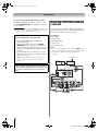
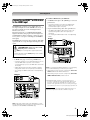
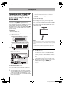
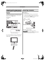
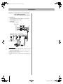
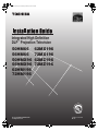
DLP_Inst.book Page 1 Wednesday, February 22, 2006 6:18 PM
Integrated High Definition
DLP™ Projection Television
62MX196
72MX196
62MZ196
72MZ196
© 2006 TOSHIBA CORPORATION
All Rights Reserved
140
45
IS
O
CONSUMER PR
CA
RI
S, L.L.C.
UCT
OD
TOSHIBA AM
E
50HM66
56HM66
50HMX96
56HMX96
62HM196
72HM196
01 FILE N o. A 9
6
YC/N VX1A00004000
DLP_Inst.book Page 2 Wednesday, February 22, 2006 6:18 PM
Dear Customer,
NOTICE OF POSSIBLE TV STAND INSTABILITY
Thank you for purchasing this Toshiba TV. This manual will
help you use the many exciting features of your new TV. Before
operating the TV, please read this manual completely, and
keep it nearby for future reference.
CAUTION: This television is for use only with
the Toshiba stand listed in the “Specifications”
section in the Operating Guide. Use with other
carts or stands is capable of resulting in instability
causing possible injury.
Safety Precautions
WARNING: TO REDUCE THE RISK OF FIRE OR
ELECTRIC SHOCK, DO NOT EXPOSE THIS APPLIANCE
TO RAIN OR MOISTURE.
WARNING
RISK OF ELECTRIC SHOCK
DO NOT OPEN.
WARNING: TO REDUCE THE RISK OF ELECTRIC SHOCK,
DO NOT REMOVE COVER (OR BACK). NO USERSERVICEABLE PARTS INSIDE. REFER SERVICING TO
QUALIFIED SERVICE PERSONNEL. (This does not apply to “Lamp
unit replacement and care” in the Operating Guide.)
The lightning flash with arrowhead symbol, within an
equilateral triangle, is intended to alert the user to the
presence of uninsulated “dangerous voltage” within
the product’s enclosure that may be of sufficient
magnitude to constitute a risk of electric shock to
persons.
The exclamation point within an equilateral triangle is
intended to alert the user to the presence of important
operating and maintenance (servicing) instructions in
the literature accompanying the appliance.
NOTE TO CATV INSTALLERS IN THE U.S.A.
This is a reminder to call the CATV system installer’s attention
to Article 820-40 of the U.S. NEC, which provides guidelines for
proper grounding and, in particular, specifies that the cable
ground shall be connected to the grounding system of the building,
as close to the point of cable entry as practical. For additional
antenna grounding information, see items 27 and 28 on page 4.
Child Safety
It Makes A Difference
Where Your TV Stands
Congratulations on your purchase!
As you enjoy your new TV, keep these safety tips in mind:
The Issue
a If you are like most consumers, you have a TV in your home.
Many homes, in fact, have more than one TV.
a The home theater entertainment experience is a growing trend,
and larger TVs are popular purchases; however, they are not
always supported on the proper TV stands.
a Sometimes TVs are improperly secured or inappropriately
situated on dressers, bookcases, shelves, desks, audio
speakers, chests, or carts. As a result, TVs may fall over,
causing unnecessary injury.
Lamp Unit Replacement
Toshiba Cares!
a The consumer electronics industry
is committed to making home entertainment
enjoyable and safe.
a The Consumer Electronics Association
formed the Home Entertainment Support
Safety Committee, comprised of TV and
consumer electronics furniture
manufacturers, to advocate children’s safety
and educate consumers and their families
about television safety.
The lamp in this product has a limited service life. The length
of service life varies depending on product use and user
settings. If you use the lamp beyond its service life:
• you may notice a reduction in the colors and/or brightness
of the picture, at which time you should replace the lamp
unit; and
• the strength of the quartz glass in the lamp will be reduced
and the lamp may rupture. If the lamp ruptures, the TV will
not operate until the lamp unit is replaced.
Dispose of the used lamp unit by the approved method for
your area.
See “Lamp unit replacement and care”
in the Operating Guide.
Note: The lamp unit contains mercury.
Disposal of mercury may be regulated due to
environmental considerations. For disposal or recycling
information, contact your local authorities or the Electronic
Industries Alliance (www.eiae.org).
Tune Into Safety
a
a
a
a
a
a
a One size does NOT fit all! Use appropriate furniture large
enough to support the weight of your TV (and other electronic
components).
Use appropriate angle braces, straps, and anchors to secure your
furniture to the wall (but never screw anything directly into the TV).
Carefully read and understand the other enclosed
instructions for proper use of this product.
Do not allow children to climb on or play with furniture and TVs.
Avoid placing any item on top of your TV (such as a VCR, remote
control, or toy) that a curious child may reach for.
Remember that children can become excited while watching
a program and can potentially push or pull a TV over.
Share our safety message about this hidden hazard of the home
with your family and friends. Thank you!
2500 Wilson Blvd.
Arlington, VA 22201 U.S.A.
Tel. 703-907-7600 Fax 703-907-7690
www.CE.org
CEA is the Sponsor, Producer and
Manager of the International CES ®
2
DLP Inst (E/F) Web 213:276
DLP_Inst.book Page 3 Wednesday, February 22, 2006 6:18 PM
Important Safety Instructions
1)
Read these instructions.
2)
3)
4)
Keep these instructions.
Heed all warnings.
Follow all instructions.
5)
Do not use this apparatus near water.
6)
Clean only with dry cloth.
7)
Do not block any ventilation openings. Install in
accordance with the manufacturer’s instructions.
8)
Do not install near any heat sources such as radiators,
heat registers, stoves, or other apparatus (including
amplifiers) that produce heat.
9)
Do not defeat the safety purpose of Wide blade
the polarized or grounding type
plug. A polarized plug has two blades
with one wider than the other.
A grounding type plug has two blades
and a third grounding prong. The wide blade or the third
prong are provided for your safety. If the provided plug
does not fit into your outlet, consult an electrician for
replacement of the obsolete outlet.
10) Protect the power cord from being walked
on or pinched, particularly at plugs,
convenience receptacles, and the point
where they exit from the apparatus.
11) Only use attachments/accessories specified by the
manufacturer.
12) Use only with the cart, stand, tripod,
bracket, or table specified by the
manufacturer, or sold with the
apparatus. When a cart is used, use
caution when moving the cart/apparatus
combination to avoid injury from tip-over.
13) Unplug this apparatus during lightning storms or
when unused for long periods of time.
14) Refer all servicing to qualified service personnel.
Servicing is required when the apparatus has been
damaged in any way, such as power-supply cord or plug
is damaged, liquid has been spilled or objects have fallen
into the apparatus, the apparatus has been exposed to
rain or moisture, does not operate normally, or has been
dropped.
Additional Safety Precautions
14a) Item 14 does not apply to “Lamp unit replacement and
care” in the Operating Guide.
14b) CAUTION: If the TV is dropped and the cabinet or
enclosure surface has been damaged or the TV does
not operate normally, take the following precautions:
• ALWAYS turn off the TV and unplug the power cord to
avoid possible electric shock or fire.
• To prevent personal injury, never handle the damaged
television.
• ALWAYS contact a service technician to inspect the TV
any time it has been damaged or dropped.
15) CAUTION:
• To reduce the risk of electric shock, do not use the
polarized plug with an extension cord, receptacle, or
other outlet unless the blades can be inserted
completely to prevent blade exposure.
• To prevent electric shock, match wide blade of plug to
wide slot; fully insert.
16) WARNING: This product contains a lamp to project
the picture, and requires special safety precautions:
• See the Operating Guide for instructions on lamp unit
replacement and care.
• DO NOT attempt to service this product except as
specified in the “Lamp unit replacement and care”
section in the Operating Guide. The only userserviceable item in this product is the lamp unit.
Installation, Care, and Service
Installation
Follow these recommendations and precautions and heed all
warnings when installing your TV:
17) Never modify this equipment. Changes or modifications
may void: a) the warranty, and b) the user’s authority to
operate this equipment under the rules of the Federal
Communications Commission.
18)
DANGER: RISK OF
SERIOUS PERSONAL
INJURY, DEATH, OR
EQUIPMENT DAMAGE!
Never place the TV on an unstable cart,
stand, or table. The TV may fall, causing
serious personal injury, death, or serious
damage to the TV.
19) Never place or store the TV in direct sunlight; areas
subject to excessive dust or vibration; or locations with
temperatures at or below 41°F (5°C). See “Specifications”
section in the Operating Guide on operating conditions.
20) Always place the TV on the applicable optional TV
stand(s) listed in the “Specifications” section in the
Operating Guide (if available for this TV model) or on a
sturdy, level, stable surface that can safely support the
size and weight of the unit. See “Notice of possible TV
stand instability” and “Child Safety” on page 2.
21) The apparatus shall not be exposed to dripping or
splashing and that no objects filled with liquids, such as
vases, shall be placed on the apparatus.
22) Always place the back of the television at least one (1)
inch away from any vertical surface (such as a wall) to
allow proper ventilation.
23) Never block or cover the slots or openings in the TV
cabinet back, bottom, and sides. Never place the TV:
• on a bed, sofa, rug, or similar surface;
• too close to drapes, curtains, or walls; or
• in a confined space such as a bookcase, built-in
cabinet, or any other place with poor ventilation.
The slots and openings are provided to protect the TV
from overheating and to help maintain reliable operation of
the TV.
3
DLP Inst (E/F) Web 213:276
DLP_Inst.book Page 4 Wednesday, February 22, 2006 6:18 PM
24) Never allow anything to rest on or roll over the power cord,
and never place the TV where the power cord is subject to
wear or abuse.
25) Never overload wall outlets and extension cords.
26) Always operate this equipment from a 120 VAC, 60 Hz
power source only.
27) Always make sure the antenna system is properly
grounded to provide adequate protection against voltage
surges and built-up static charges (see Section 810 of the
National Electric Code).
Antenna lead-in wire
Ground clamp
Electric service equipment
Ground clamps
28)
Antenna discharge unit
(NEC Section 810-20)
Grounding conductors
(NEC Section 810-21)
Power service grounding
electrode system (NEC Art 250 Part-H)
DANGER: RISK OF SERIOUS
PERSONAL INJURY OR DEATH!
• Use extreme care to make sure you are never in a
position where your body (or any item you are in contact
with, such as a ladder or screwdriver) can accidentally
touch overhead power lines. Never locate the antenna
near overhead power lines or other electrical circuits.
• Never attempt to install any of the following during
lightning activity: a) an antenna system; or b) cables,
wires, or any home theater component connected to an
antenna or phone system.
34) During normal use, the TV may make occasional snapping
or popping sounds. This is normal, especially when the
unit is being turned on or off. If these sounds become
frequent or continuous, unplug the power cord and contact
a Toshiba Authorized Service Center.
35) Special care for DLP™ (Digital Light Processing)
units:
• The lamp unit in this product has a limited service life.
The length of service life varies depending on product
use or user settings. If you use the lamp beyond its
service life:
• you may notice a reduction in the colors and/or
brightness of the picture, at which time you should
replace the lamp unit; and
• the strength of the quartz glass in the lamp will be
reduced and the lamp may rupture. If the lamp ruptures,
the TV will not operate until the lamp unit is replaced.
See “Lamp unit replacement and care” in the Operating
Guide.
• Dispose of the used lamp unit by the approved method
for your area.
•
The lamp unit contains mercury. Disposal of
mercury may be regulated due to
environmental considerations. For disposal or
recycling information, please contact your
local authorities or the Electronic Industries
Alliance (www.eiae.org).
Service
36)
WARNING:
RISK OF ELECTRIC SHOCK!
Care
For better performance and safer operation of your TOSHIBA
TV, follow these recommendations and precautions:
29) Always sit approximately 10–25 feet away from the TV and
as directly in front of it as possible. The picture can appear
dull if you sit too far to the left or right of the TV, or if
sunlight or room lights reflect on the screen. Turn the TV
off to check for reflections on the screen, and then remove
the source of reflections while viewing the TV.
30) Always unplug the TV before cleaning. Never use liquid or
aerosol cleaners. Clean only with a soft, dry cloth. Do not
spray volatile compounds, such as insecticide, on the
cabinet. This may discolor or damage the cabinet.
31)
33) For added protection of your TV from lightning and power
surges, always unplug the power cord and disconnect the
antenna from the TV if you leave the TV unattended or
unused for long periods of time.
WARNING:
RISK OF ELECTRIC SHOCK!
Never spill liquids or push objects of any kind into the TV
cabinet slots.
32) If the air temperature rises suddenly (for example, when
the TV is first delivered), condensation may form on the
lenses. This can make the picture appear distorted or the
color appear faded. If this happens, turn off the TV for 6 to
7 hours to allow the condensation to evaporate.
Never attempt to service the TV yourself, except as
specified in the “Lamp unit replacement and care” section
in the Operating Guide. Opening and removing the covers
may expose you to dangerous voltage or other hazards.
Failure to follow this WARNING may result in death or
serious injury. Refer all servicing not specified in this
manual to a Toshiba Authorized Service Center.
37) If you have the TV serviced:
• Ask the service technician to use only replacement
parts specified by the manufacturer.
• Upon completion of service, ask the service technician
to perform routine safety checks to determine that the
TV is in safe operating condition.
38) When the TV reaches the end of its useful life, ask a
qualified service technician to properly dispose of the TV.
Note: The lamp unit contains mercury. Disposal of
mercury may be regulated due to environmental
considerations. Dispose of the used lamp unit by the
approved method for your area.
For disposal or recycling information, please contact your
local authorities or the Electronic Industries Alliance
(www.eiae.org).
Digital Light Processing™, DLP™ and the DLP™ medallion are
trademarks of Texas Instruments.
4
DLP Inst (E/F) Web 213:276
DLP_Inst.book Page 5 Wednesday, February 22, 2006 6:18 PM
Welcome to Toshiba
Thank you for purchasing this Toshiba TV, one of the most innovative DLP™ projection TVs on the market.
This digital television is capable of receiving analog basic, digital basic and digital premium cable television programming by
direct connection to a cable system providing such programming. A security card provided by your cable operator is required to
view encrypted digital programming. Certain advanced and interactive digital cable services such as video-on-demand, a cable
operator's enhanced program guide and data-enhanced television services may require the use of a set-top box. For more
information call your local cable operator.
We have provided three separate Guides to facilitate the installation and operation of your TV.
Please use the Guides in the order shown below to get the most enjoyment from your new TV.
1) The “Installation Guide” explains how to connect your TV to your antenna and equipment.
2) The “Operating Guide” provides step-by-step instructions for using your TV’s many features.
3) The “TV Guide On Screen™ Interactive Program Guide” explains how to set up and navigate the TV Guide On Screen™
system in your TV.
Notes:
• Models 50HM66 and 56HM66 do not have the TV Guide On Screen™ feature; therefore, the TV Guide On Screen™ Interactive
Program Guide is not provided in the accessory pack.
• Screen captures provided in this Installation Guide may not match the screens that you see on your TV. Please refer to your
Operating Guide.
Terminal Specifications for DLP™ Projection Televisions
This Installation Guide includes installation instructions for several television models. Please confirm your TV’s terminal
specifications in the following table to determine which connection in this Guide is appropriate for your particular TV.
Note: The model number is on the back of your TV.
Input/Output Terminals
RF Input
Video/Audio Input
(composite video/analog audio)
50/56HM66
62/72HM196
50/56HMX96
62/72MX196
62/72MZ196
Yes (2)
Yes (2)
Yes (2)
Yes (2)
Yes (2)
Yes (2 sets)
Yes (2 sets)
Yes (2 sets)
Yes (2 sets)
Yes (2 sets)
S-Video Input
Yes (2 sets)
Yes (2 sets)
Yes (2 sets)
Yes (2 sets)
Yes (2 sets)
ColorStream HD Input
Yes (2 sets)
Yes (2 sets)
Yes (2 sets)
Yes (2 sets)
Yes (2 sets)
Yes (2)
Yes (2)
Yes (2)
Yes (2)
Yes (2)
PC Input
No
No
Yes
Yes
Yes
Video/Audio Output
(composite video/analog audio)
Yes
Yes
Yes
Yes
Yes
Variable Audio Output (analog)
Yes
Yes
Yes
Yes
Yes
Digital Audio Output (optical)
Yes
Yes
Yes
Yes
Yes
Ethernet
No
Yes
Yes
Yes
Yes
IR In
No
No
No
No
Yes
IR Out (pass-through)
Yes
Yes
Yes
Yes
Yes
G-LINK™
No
Yes
Yes
Yes
Yes
CableCARD™ Slot
Yes
Yes
Yes
Yes
Yes
TV Guide On Screen™ System
No
Yes
Yes
Yes
Yes
HDMI Input
5
DLP Inst (E/F) Web 213:276
DLP_Inst.book Page 6 Wednesday, February 22, 2006 6:18 PM
Contents
Important Safety Instructions . . . . . . . . . . . . . . . .3
Installation, Care, and Service . . . . . . . . . . . . . . .3
Welcome to Toshiba . . . . . . . . . . . . . . . . . . . . . .5
Terminal Specifications for DLP™ Projection
Televisions . . . . . . . . . . . . . . . . . . . . . . . . . .5
Connecting your TV . . . . . . . . . . . . . . . . . . . . . . .7
Overview of cable types . . . . . . . . . . . . . . . . . . . . . . . . . . 7
About the connection illustrations . . . . . . . . . . . . . . . . . . 8
Connecting a digital CableCARD™. . . . . . . . . . . . . . . . . 8
Connecting a VCR and antenna or Cable TV
(no Cable box) . . . . . . . . . . . . . . . . . . . . . . . . . . . . . . 9
Connecting a VCR and Cable box . . . . . . . . . . . . . . . . . 10
Connecting a DVD player with ColorStream®
(component video), a VCR, and a satellite
receiver . . . . . . . . . . . . . . . . . . . . . . . . . . . . . . . . . . . 11
Connecting a VCR with S-video and a cable box . . . . . 12
Connecting an HDMI™ or DVI device to the
HDMI input . . . . . . . . . . . . . . . . . . . . . . . . . . . . . . . 13
Connecting a device to the IR OUT infrared terminal
using the IR blaster cable for IR pass-through
device control . . . . . . . . . . . . . . . . . . . . . . . . . . . . . . 14
Connecting an IR receiver/repeater control system to
the IR IN infrared terminal . . . . . . . . . . . . . . . . . . . . 15
Connecting a camcorder . . . . . . . . . . . . . . . . . . . . . . . . . 15
Connnecting a digital audio system . . . . . . . . . . . . . . . . 16
Connecting an analog audio system . . . . . . . . . . . . . . . . 16
G-LINK™ connection . . . . . . . . . . . . . . . . . . . . . . . . . . 17
Connecting a personal computer (PC) . . . . . . . . . . . . . . 18
Connecting a home network . . . . . . . . . . . . . . . . . . . . . . 19
Index . . . . . . . . . . . . . . . . . . . . . . . . . . . . . . . . 21
6
DLP Inst (E/F) Web 213:276
DLP_Inst.book Page 7 Wednesday, February 22, 2006 6:18 PM
Connecting your TV
Overview of cable types
both video and audio information; therefore, separate audio
cables are not required for a complete HDMI device
connection (- page 13).
Coaxial (F-type) cable
Note: HDMI cable provides better picture performance than a
standard (composite) video or S-video cable.
Coaxial (F-type) cable is used for connecting your antenna,
cable TV service, and/or cable converter box to the ANT 1
and/or ANT 2 RF inputs on your TV.
Standard A/V cables (red/white/yellow)
Standard A/V cables (composite video) usually come in sets of
three, and are for use with video devices with analog audio and
composite video output. These cables (and the related inputs
on your TV) are typically color-coded according to use: yellow
for video, red for stereo right audio, and white for stereo left
(or mono) audio.
S-video cable
S-video cable is for use with video devices with S-video
output. Separate audio cables are required for a complete
connection.
Note: An S-video cable provides better picture performance
than a composite video cable. If you connect an S-video cable,
be sure to disconnect the standard (composite) video cable or
the picture performance will be unacceptable.
Component video cables (red/green/blue)
Dual-wand IR blaster/G-LINK™ cable
Dual-wand IR blaster/G-LINK™ cable is for use with video
devices with IR (infrared) remote control. This cable is for
connection to the G-LINK™ terminal (- page 17) to enable
TV Guide On Screen™ recording features (- TV Guide
On Screen™ Interactive Program Guide). This cable also can
be used with the TV’s IR pass-through feature (- page 14).
Notes:
• This applies only to TV models that have the TV Guide
On Screen™ feature. To verify whether your TV model has
this feature, see the table on page 5.
• The IR blaster/G-LINK™ cable included with your TV have
specific characteristics that allow them to work properly with
this TV’s IR OUT and G-LINK™ ports. Never use other
aftermarket IR blaster or G-LINK™ cables with this TV. Other
cables may not function properly and can cause damage.
THIS TYPE OF DAMAGE IS NOT COVERED BY YOUR
TOSHIBA WARRANTY.
Optical audio cable
Optical audio cable is for connecting receivers with Dolby
Digital or PCM (pulse-code modulation) optical audio input to
the TV’s DIGITAL AUDIO OUT terminal (- page 16).
Analog RGB (15-pin) computer cable
Component video cables come in sets of three and are for use
with video devices with component video output.
(ColorStream® is Toshiba’s brand of component video.) These
cables are typically color-coded red, green, and blue. Separate
audio cables are required for a complete connection.
Note: Component video cables provide better picture
performance than a standard (composite) video or S-video
cable.
HDMI™ cable
Analog RGB (15-pin) computer cable is for connecting a PC to
the TV’s PC IN terminal (- page 18).
Ethernet (RJ-45) cable
Ethernet (RJ-45) cable is used to connect the TV to your home
network (- page 19 and the Operating Guide).
HDMI (High-Definition Multimedia Interface) cable is for use
with devices with an HDMI output. An HDMI cable delivers
digital audio and video in its native format. This cable carries
7
DLP Inst (E/F) Web 213:276
DLP_Inst.book Page 8 Wednesday, February 22, 2006 6:18 PM
Connecting your TV
About the connection illustrations
You can connect different types and brands of devices to your
TV in several different configurations. The connection
illustrations in this manual are representative of typical device
connections only. The input/output terminals on your devices
may differ from those illustrated herein. For details on
connecting and using your specific devices, refer to each
device’s owner’s manual.
2
With the front of the CableCARD™ facing up, insert it
into the CableCARD™ slot on the back of the TV (see
illustration below left).
3
After the CableCARD™ is inserted, a CableCARD™
option appears in the Applications menu, with
informational screens provided by your digital
CableCARD™ service. See “Viewing the CableCARD™
menu” in the Operating Guide for additional information.
CableCard Connected -- Acquiring
channel information.
Applications
CableCard services will only operate
with cable signal connected to Antenna 1.
Connecting a digital CableCARD™
This digital television is capable of receiving analog basic,
digital basic, and digital premium cable television
programming by direct connection to a cable system providing
such programming.
A security card (such as a digital CableCARD™), provided by
your cable operator, is required to view encrypted digital
programming.
Certain advanced and interactive digital cable services (such as
video-on-demand, a cable operator’s enhanced program guide,
and data-enhanced television services) will not work with the
use of a CableCARD™ and may require the use of a separate
set-top box from your cable operator.
For more information, contact your local cable operator.
You will need:
• digital CableCARD™ (contact your cable operator)
• digital cable subscription service (contact your cable
operator)
TV back panel
From digital Cable service
To view encrypted digital channels:
1
Connect your digital Cable TV cable to ANT 1.
Channel Browser
Digital CC/Audio Selector
CableCARD
IP Service
Conditional Access
CableCARD(tm) Status
Network Setup
CableCARD(tm) Pairing
Navigate ENTER Select
CH RTN Back
EXIT Exit
Notes:
• Connect the cable from your digital cable TV service directly
to ANT 1 only. If you connect the digital cable through a
VCR first and/or to ANT 2, the TV may not receive the signals
correctly.
• Always use the EJECT button to remove the CableCARD™.
Removing the CableCARD™ without pressing EJECT can
damage the CableCARD™ and/or TV. Such damage is NOT
covered under your Toshiba warranty.
• Never insert any object or card other than a CableCARD™
(including, without limitation, a PCMCIA card) into the
CableCARD™ slot.
• Always make sure the CableCARD™ is facing the correct
direction.
• When using a CableCARD™, you do not need to program
channels into the TV memory. The CableCARD™
automatically loads the cable channel list into the TV’s
channel memory (- Operating Guide).
• The CableCARD™ may take about 5 minutes to “pair” with
the TV and download channel information. CableCARD™
information and channels will not be available until this
process is completed.
• Connecting your TV directly to the Audio/Video output of
your Set-Top-Box will assure a more vivid picture and
enhance your viewing enjoyment.
CableCARD™ technology, like all new and emerging
technology, may from time to time experience compatibility
issues due to the different ways in which television
manufacturers and cable system operators implement the
CableCARD™ specifications. Most issues can be easily
resolved. If you experience any performance-related
CableCARD™ issues with your Toshiba television, please
contact the following:
In the U.S.:
• Call TACP Consumer Solutions at (800) 631-3811
• Or visit
http://www.tacp.com/customersupport/contact.asp.
In Canada:
• Call TCL Customer Service at 1-800-268-3404.
CableCARD is a trademark of Cable Television Laboratories, Inc.
8
DLP Inst (E/F) Web 213:276
DLP_Inst.book Page 9 Wednesday, February 22, 2006 6:18 PM
Connecting your TV
Connecting a VCR and antenna or
Cable TV (no Cable box)
To use the TV Guide On Screen™ recording
features (if applicable to your TV model):
You will need:
2
• signal splitter
• coaxial cables
• standard A/V cables
1
3
– For better picture performance, if your VCR has S-video,
use an S-video cable (plus the audio cables) instead of
the standard video cable. Do not connect both types of
video cable to VIDEO 1 at the same time or the picture
performance will be unacceptable.
– If you have a mono VCR, connect L/MONO on the TV to
your VCR’s audio out terminal using the white audio cable
only.
Note: The VIDEO/AUDIO OUT terminals output signals from
the ANT 1, ANT 2, VIDEO 1, and VIDEO 2 terminals when the
applicable input mode is selected.*
From Cable TV or antenna
Signal splitter
IN
4
Connect the G-LINK™ cable according to the
instructions (- page 17).
Make sure the VCR is connected to the VIDEO/
AUDIO OUT terminals on the TV (see illustration).
Set the VCR to the appropriate line input (refer to your
VCR owner’s manual for details), and then turn OFF
the VCR.
See the TV Guide On Screen™ Interactive Program
Guide for details on setting up and using the TV Guide
On Screen™ system.
The unauthorized recording, use, distribution, or revision of
television programs, videotapes, DVDs, and other materials is
prohibited under the Copyright Laws of the United States and
other countries, and may subject you to civil and criminal
liability.
In the United States, TV GUIDE and other related marks are registered
marks of Gemstar-TV Guide International, Inc. and/or one of its
affiliates. In Canada, TV GUIDE is a registered mark of
Transcontinental Inc., and is used under license by Gemstar-TV Guide
International, Inc.
OUT
OUT
Stereo VCR
VIDEO
IN from ANT
L
AUDIO
R
IN IN
CH 3
CH 4
OUT
OUT to TV
L
R
TV
To view the antenna or Cable signal:
Select the ANT 1 video input source on the TV.*
To view the VCR:
Turn ON the VCR. Select the VIDEO 1 video input source on
the TV.*
* To select the video input source, press INPUT on the remote control
(- Operating Guide). To program the TV remote control to operate
other devices, see the Operating Guide, Chapter 2.
9
DLP Inst (E/F) Web 213:276
DLP_Inst.book Page 10 Wednesday, February 22, 2006 6:18 PM
Connecting your TV
Connecting a VCR and Cable box
You will need:
To view the VCR:
Turn ON the VCR. Select the VIDEO 1 video input source on
the TV.*
* To select the video input source, press INPUT on the remote control
(- Operating Guide). To program the TV remote control to operate
other devices, see the Operating Guide, Chapter 2.
• signal splitter
• coaxial cables
• standard A/V cables
– For better picture performance, if your VCR has S-video,
connect an S-video cable (plus the audio cables) instead
of the standard video cable. Do not connect both types of
video cable to VIDEO 1 at the same time or the picture
performance will be unacceptable.
– If you have a mono VCR, connect L/MONO on the TV to
your VCR’s audio out terminal using the white audio cable
only.
– When you use a Cable box, you may not be able to use
the remote control to program or access certain features
on the TV.
Note: The VIDEO/AUDIO OUT terminals output signals from
the ANT 1, ANT 2, VIDEO 1, and VIDEO 2 terminals when the
appropriate input mode is selected.*
To enable the TV Guide On Screen™ system to
work with your cable box and to use the TV Guide
On Screen™ recording features (if applicable to
your TV model):
1
2
3
4
Connect the G-LINK™ cable according to the
instructions (- page 17).
Make sure the VCR is connected to the VIDEO/
AUDIO OUT terminals on the TV (see illustration).
Set the VCR to the appropriate line input (refer to your
VCR owner’s manual for details), and then turn OFF
the VCR.
See the TV Guide On Screen™ Interactive Program
Guide for details on setting up and using the TV Guide
On Screen™ system.
From Cable TV
Cable box
Signal splitter
IN
OUT
IN
CH 3
CH 4
OUT
OUT
The unauthorized recording, use, distribution, or revision of
television programs, videotapes, DVDs, and other materials is
prohibited under the Copyright Laws of the United States and
other countries, and may subject you to civil and criminal
liability.
Stereo VCR
VIDEO
IN from ANT
L
AUDIO
R
IN IN
CH 3
CH 4
OUT
OUT to TV
L
R
TV
To view basic Cable channels and use the TV’s
features:
Select the ANT 1 video input source on the TV.* Use the TV
controls (control panel or remote control) to change channels
and access the TV’s features.
To view basic and premium Cable channels:
Turn OFF the VCR. Select the ANT 2 video input source on
the TV.* Tune the TV to channel 3 or 4 (whichever channel the
Cable box output is set to). Use the Cable box controls to
change channels.
10
DLP Inst (E/F) Web 213:276
DLP_Inst.book Page 11 Wednesday, February 22, 2006 6:18 PM
Connecting your TV
Connecting a DVD player with
ColorStream® (component video),
a VCR, and a satellite receiver
From antenna
Signal splitter
IN
OUT
OUT
Stereo VCR
Your TV has two sets of ColorStream® (component video)
inputs.
VIDEO
IN from ANT
You will need:
L
AUDIO
R
IN IN
CH 3
CH 4
OUT
OUT to TV
L
• signal splitter
• coaxial cables
• standard A/V cables
R
TV
– For better picture performance, if your VCR has S-video,
use an S-video cable (plus the audio cables) instead of
the standard video cable. Do not connect both types of
video cable to VIDEO 1 at the same time or the picture
performance will be unacceptable.
– If you have a mono VCR, connect L/MONO on the TV to
your VCR’s audio out terminal using the white audio cable
only.
• standard audio cables
• component video cables
– You can connect the component video cables (plus audio
cables) from the DVD player or satellite receiver to either
set of ColorStream terminals on the TV (HD-1 or HD-2).
The ColorStream HD-1 and HD-2 terminals can be used
with Progressive (480p, 720p) and Interlaced (480i, 1080i)
scan systems. A 1080i signal will provide the best picture
performance.
– If your DVD player or satellite receiver does not have
component video, connect an S-video cable (plus audio
cables) to VIDEO 2 on the side panel. If your DVD player
has HDMI video, see page 13.
Note: The VIDEO/AUDIO OUT terminals output signals from
the ANT 1, ANT 2, VIDEO 1, and VIDEO 2 terminals when the
appropriate input mode is selected.*
* To select the video input source, press INPUT on the remote control
(- Operating Guide). To program the TV remote control to operate
other devices, see the Operating Guide, Chapter 2.
DVD player with
component video
AUDIO
OUT
Y
S-VIDEO
OUT
L
PR
PB
COMPONENT VIDEO
VIDEO
OUT
R
From satellite dish
AUDIO
OUT
Y
Satellite S-VIDEO
IN
OUT
PB
L
PR
COMPONENT VIDEO
VIDEO
OUT
R
Satellite receiver with component video
To view antenna or Cable channels:
Select the ANT 1 video input source on the TV.*
To view the DVD player:
Turn ON the DVD player. Select the ColorStream HD-1
video input source on the TV.*
To view satellite programs using the component video
connections or to record satellite programs:
Turn on all three devices. Set the VCR to the appropriate line
input (refer to your VCR owner’s manual for details). Select
the ColorStream HD-2 video input source on the TV.*
To view the VCR or view and record antenna
channels:
Turn ON the VCR. Tune the VCR to the channel you want to
watch. Select the VIDEO 1 video input source on the TV.*
(continued)
11
DLP Inst (E/F) Web 213:276
DLP_Inst.book Page 12 Wednesday, February 22, 2006 6:18 PM
Connecting your TV
To record a TV program while watching a DVD:
Turn ON the VCR. Tune the VCR to the channel to record.
Select the ColorStream HD-1 video input source on the TV*
to view the DVD.
* To select the video input source, press INPUT on the remote control
(- Operating Guide). To program the TV remote control to operate
other devices, see the Operating Guide, Chapter 2.
To use the TV Guide On Screen™ recording
features (if applicable to your TV model):
1
2
3
4
Connect the G-LINK™ cable according to the
instructions (- page 17).
Make sure the VCR is connected to the VIDEO/
AUDIO OUT terminals on the TV (see illustration).
Set the VCR to the appropriate line input (refer to your
VCR owner’s manual for details), and then turn OFF
the VCR.
See the TV Guide On Screen™ Interactive Program
Guide for details on setting up and using the TV Guide
On Screen™ system.
Note: The TV Guide On Screen™ system does not
receive program listings from or for any satellite
service.
Connecting a VCR with S-video and
a cable box
An S-video connection will provide better picture performance
than a standard (composite) video cable. If your VCR does not
have S-video, refer to the connection on page 10.
You will need:
•
•
•
•
•
signal splitter
coaxial cables
standard A/V cables
S-video cable
standard audio cables
Notes:
• Do not connect both types of video cable to VIDEO 1 at the
same time or the picture performance will be unacceptable.
• See page 10 for details on the VCR and Cable box
connection.
From Cable TV
Cable box
IN
OUT
The unauthorized recording, use, distribution, or revision of
television programs, videotapes, DVDs, and other materials is
prohibited under the Copyright Laws of the United States and
other countries, and may subject you to civil and criminal
liability.
Signal splitter
IN
CH 3
CH 4
OUT
OUT
Stereo VCR
VIDEO
IN from ANT
L
AUDIO
R
IN IN
CH 3
CH 4
OUT
OUT to TV
L
R
TV
12
DLP Inst (E/F) Web 213:276
DLP_Inst.book Page 13 Tuesday, February 28, 2006 3:23 PM
Connecting your TV
Connecting an HDMI™ or DVI device
to the HDMI input
The HDMI input on your TV receives digital audio and
uncompressed digital video from an HDMI source device, or
uncompressed digital video from a DVI (Digital Visual
Interface) source device.
This input is designed to accept HDCP (High-Bandwidth
Digital-Content Protection) program material in digital form
from EIA/CEA-861-861B–compliant[1] consumer electronic
devices (such as a set-top box or DVD player with HDMI or
DVI output).
The HDMI input is designed for best performance with 1080i
signals but will also accept and display 480i, 480p and 720p
signals.
NOTE: DO NOT CONNECT A PC USING
THE HDMI PORT. Always use the TV’s PC
IN (VGA) port to connect a PC.
To connect a DVI device, you will need:
• one HDMI-to-DVI adapter cable (HDMI type A connector)
per DVI device
– For proper operation, the length of an HDMI-to-DVI
adapter cable should not exceed 9.8 ft (3m). The
recommended length is 6.6 ft (2m).
• one pair of standard analog audio cables per DVI device
– An HDMI-to-DVI adapter cable transfers video only.
Separate analog audio cables are required (see
illustration).
– See “Setting the HDMI™ audio mode” in the Operating
Guide.
DVI device
VIDEO
L
DVI/HDCP
OUT
AUDIO
R
IN IN
OUT
L
R
TV
• The HDMI port is not designed to support input from a
PC.
• Only models that include a PC IN (VGA) port are suitable
for connection to a PC.
To connect an HDMI device, you will need:
• one HDMI cable (type A connector) per HDMI device
– For proper operation, it is recommended that you use as
short an HDMI cable as possible. You should not
encounter difficulty if you use an HDMI cable shorter than
16.4 ft (5m).
– HDMI cable transfers both video and audio. Separate
analog audio cables are not required (see illustration).
– See “Setting the HDMI™ audio mode” in the Operating
Guide.
HDMI device
VIDEO
L
AUDIO
R
HDMI OUT
Note: To ensure that the HDMI or DVI device is reset properly,
it is recommended that you follow these procedures:
• When turning on your electronic components, turn on the
TV first, and then the HDMI or DVI device.
• When turning off your electronic components, turn off the
HDMI or DVI device first, and then the TV.
IN IN
OUT
L
R
TV
[1] EIA/CEA-861-861B compliance covers the transmission of
uncompressed digital video with high-bandwidth digital content
protection, which is being standardized for reception of highdefinition video signals. Because this is an evolving technology, it
is possible that some devices may not operate properly with the TV.
HDMI, the HDMI logo and High-Definition Multimedia Interface are
trademarks or registered trademarks of HDMI Licensing LLC.
Note: If the audio output mode of the HDMI device is other
than the PCM mode, the sound does not output from the TV’s
speakers (models 50HM66 and 56HM66 only).
13
DLP Inst (E/F) Web 213:276
DLP_Inst.book Page 14 Wednesday, February 22, 2006 6:18 PM
Connecting your TV
Connecting a device to the IR OUT
infrared terminal using the IR
blaster cable for IR pass-through
device control
You can use the TV’s IR OUT terminal (infrared passthrough) to remotely operate –through the TV– many infrared
remote-controlled devices (such as a Toshiba infrared remotecontrolled VCRs or DVD player) enclosed within an
entertainment center or similar cabinet. Without the IR OUT
connection, the device typically would need to be visible to
operate it remotely.
Note: If you do not have a second device, coil the second
wand with a rubber band and leave it behind the TV.
3
Plug the IR blaster cable’s plug into the TV’s IR OUT
terminals.
To control the device(s):
Point either the device's remote control or the TV remote
control (that you previously programmed to operate the
device; - Operating Guide, Chapter 2) toward the front of the
TV and press the button for the desired function. The signal
passes from the remote control through the TV to the device
via the IR blaster cable.
You will need:
• dual-wand IR blaster cable
• other audio/video cables as required to connect the device(s)
to the TV (- pages 9–13)
Front of IR-controlled DVD player (for example)
Front of IR-controlled audio device (for example)
Infrared
sensor
Notes:
• If you use the device’s remote control to operate the device,
you also will need to use the TV’s remote control to operate
the TV.
• The IR pass-through feature does not support all IRcontrolled devices; satisfactory performance may not be
attainable with certain devices.
*If you cannot locate the device’s infrared sensor:
IR blaster cable wand
(approx.1 inch from device)
TV
1
2
3
4
5
Turn OFF the device.
Starting at the lower left corner of the device, place the
end of the device’s remote control (with the infrared
emitter) so it touches the front of the device and press
POWER. (Do not use the TV’s remote control for this
step.)
If the device turns on, the point at which the remote
control touched the device is the location of the sensor.
If the device does not turn on, move the remote control
slightly to the right and press POWER again.
Repeat step 4 until you locate the device’s infrared
sensor.
To connect the IR blaster cable:
1
Locate the infrared sensor on the front of your device.
This sensor is marked on some devices.*
2
Align one of the IR blaster cable’s wands about 1 inch
away from the infrared sensor on the front of the device
and attach it using double-sided mounting tape. If you
have a second device, attach the second wand in a similar
manner. (See illustration.)
14
DLP Inst (E/F) Web 213:276
DLP_Inst.book Page 15 Wednesday, February 22, 2006 6:18 PM
Connecting your TV
Connecting an IR receiver/repeater
control system to the IR IN infrared
terminal
For additional control options for your home theater system,
you can connect an IR receiver/repeater control system (not
included) to the TV’s IR IN terminal.
You will need:
Connecting a camcorder
You will need:
• standard A/V cables
– For better picture performance, if your camcorder has
S-video, use an S-video cable (plus the audio cables)
instead of the standard video cable. Do not connect both
types of video cable to VIDEO 2 at the same time or the
picture performance will be unacceptable.
• IR cable
Camcorder
TV
VIDEO
AUDIO
OUT
L
R
VIDEO 2 inputs on TV right side panel
OUT
IN
To view the camcorder video:
Select the VIDEO 2 video input source on the TV.*
Back of IR receiver/repeater
control system (not included)
* To select the video input source, press INPUT on the remote control
(- Operating Guide). To program the TV remote control to operate
other devices, see the Operating Guide, Chapter 2.
To operate the TV with this connection, point the Toshiba TV
remote control toward the front of the IR receiver/repeater
control system.
IR receiver/repeater
control system
15
DLP Inst (E/F) Web 213:276
DLP_Inst.book Page 16 Wednesday, February 22, 2006 6:18 PM
Connecting your TV
Connecting a digital audio system
The TV’s DIGITAL AUDIO OUT terminal outputs a Dolby®*
Digital g or 2-channel down-mixed PCM (pulse-code
modulation) signal for use with an external Dolby® Digital
decoder or other external audio system with optical audio
input.
You will need:
• optical audio cable (Use an optical audio cable that has the
larger “TosLink” connector and not the smaller “minioptical” connector.)
Dolby Digital decoder or
other digital audio system
Turn off the TV’s built-in speakers in the same Audio
Setup menu. Also see “Turning off the built-in speakers”
in the Operating Guide.
Notes:
• Some audio systems may not be compatible with Dolby
Digital bitstream signals. Older audio systems that are not
compatible with standard optical out signals may not work
properly, creating a high noise level that may damage
speakers or headphones. THIS DAMAGE IS NOT COVERED
BY YOUR WARRANTY.
• The DIGITAL AUDIO OUT terminal outputs signals only
when receiving digital broadcasts with the TV in singlewindow mode.
• The DIGITAL AUDIO OUT terminal may not output some
digital audio sources because of copy restrictions.
* Manufactured under license from Dolby Laboratories. Dolby and
the double-D symbol are registered trademarks of Dolby
Laboratories.
Optical
Audio IN
LINE IN
L
R
5
TV
Connecting an analog audio system
This connection allows you to use external speakers with an
external analog audio amplifier to adjust the sound level.
You will need:
• standard audio cables
Analog audio amplifier
LINE IN
L
R
To control the audio:
1
2
Turn on the TV and the digital audio device.
3
Highlight Audio Setup and press ENTER.
Press MENU on the TV’s remote control and open the
Audio menu.
TV
Audio
Audio Settings
Advanced Audio Settings
Audio Setup
4
In the Optical Output Format field, select either
Dolby Digital or PCM, depending on your device
(- “Selecting the optical audio output format” in the
Operating Guide).
Audio Setup
MTS
Stereo
Language
English
Speakers
On
Optical Output Format
Reset
Dolby Digital
Done
To control the audio:
1
2
Turn on the TV and the stereo amplifier.
Turn off the TV’s built-in speakers (- “Turning off the
built-in speakers” in the Operating Guide).
Note: To hear sound when using an external audio amplifier,
the volume of both the TV and the amplifier must be set to a
reasonable listening level.
16
DLP Inst (E/F) Web 213:276
DLP_Inst.book Page 17 Wednesday, February 22, 2006 6:18 PM
Connecting your TV
Front of Cable box
G-LINK™ connection
Note: The G-LINK™ connection applies only to TV models that
have the TV Guide On Screen™ feature. To verify whether your
TV has this feature, see the table on page 5.
This connection is necessary for the TV Guide On Screen™
system to work with your cable box to receive program
listings and to enable the TV Guide On Screen™ recording
features with your VCR.
After you connect your devices to the TV, you will need to
connect the G-LINK™ cable from your VCR and Cable box (if
applicable) to the G-LINK™ terminal on the TV.
Front of VCR
Infrared
sensor
G-LINK™(IR blaster) cable wand
(approx.1inch from device)
TV
Note: TV Guide On Screen™ program data is available
through the ANT 1 and ANT 2 antenna inputs and also through
the VIDEO 1 inputs if you have a cable box connected to
VIDEO 1. TV Guide On Screen™ program data is not available
through any other inputs on this TV (- pages 9–16).
The G-LINK™ connection is necessary to enable the
following features of your TV Guide On Screen™ system:
• If you have a Cable box, you must connect the G-LINK™
cable from the Cable box to the G-LINK™ terminal to
receive the TV Guide On Screen™ program listings for your
Cable service.
• If you have a VCR, you must connect the G-LINK™ cable
from the VCR to the G-LINK™ terminal to use the
TV Guide On Screen™ recording features.
To connect to the G-LINK™ terminal:
1
2
3
Locate the infrared sensor on the front of your VCR or
Cable box. The sensor is marked on some devices.*
Align one of the G-LINK™ (IR blaster) cable’s wands
about 1 inch away from the infrared sensor on the front of
the VCR and attach it using double-sided mounting tape.
If you have a Cable box, attach the other wand in a similar
manner. (See illustration.)
For details on setting up and using the TV Guide
On Screen™ system:
See the TV Guide On Screen™ Interactive Program Guide
(included only with TV models that have the TV Guide
On Screen™ system).
*If you cannot locate the device’s infrared sensor:
1
2
Note: If you do not have a Cable box, coil the second
wand with a rubber band and leave it behind the TV.
3
Plug the G-LINK™ (IR blaster) cable’s plug into the TV’s
G-LINK™ terminal.
4
5
Turn OFF the device.
Starting at the lower left corner of the device, place the
end of the device’s remote control (with the infrared
emitter) so it touches the front of the device and press
POWER. (Do not use the TV’s remote control for this
step.)
If the device turns on, the point at which the remote
control touched the device is the location of the sensor.
If the device does not turn on, move the remote control
slightly to the right and press POWER again.
Repeat step 4 until you locate the device’s infrared
sensor.
17
DLP Inst (E/F) Web 213:276
DLP_Inst.book Page 18 Wednesday, February 22, 2006 6:18 PM
Connecting your TV
Connecting a personal computer
(PC)
This connection allows you to view the image from a PC on the
TV screen. When connecting a PC to the TV, use an analog
RGB (15-pin) computer cable and a PC audio cable.
Signal names for mini D-sub 15-pin
connector
Pin assignment for RGB/PC
terminal
5
10
15
TV
1
6
11
Pin No.
Computer
PC audio
cable
PC audio
output
Conversion
adapter
(if necessary)
• To use a PC, set the monitor output resolution on the PC
before connecting it to the TV. The following signals can be
displayed:
– VGA: 640 5 480 @ 60Hz
– SVGA: 800 5 600 @ 60Hz
– XGA: 1024 5 768 @ 60Hz
Signal name
1
2
R
G
3
4
B
NC (not connected)
5
6
NC
Ground
7
8
9
10
Ground
11
12
NC
NC
13
14
H-sync
V-sync
15
NC
Ground
NC
Ground
Notes:
• Some PC models cannot be connected to this TV.
• An adapter is not needed for computers with a DOS/V
compatible mini D-sub15-pin terminal.
• Depending on the DVD’s title and the specifications of the
PC on which you are playing the DVD-Video, some scenes
may be skipped or you may not be able to pause during
multi-angle scenes.
• Only models that include a PC IN (VGA) port are suitable for
connecting a PC. Never connect a PC to the HDMI port.
Other formats or non-standard signals may not be displayed
correctly.
• To display the optimum picture, use the PC setting feature
(- “Using the PC setting feature” in the Operating Guide).
18
DLP Inst (E/F) Web 213:276
DLP_Inst.book Page 19 Wednesday, February 22, 2006 6:18 PM
Connecting your TV
Connecting a home network
The Toshiba Home Interactive Network Connection
(THINC™) feature allows you to network the TV with your
home PC (personal computer), which will allow access to the
TV’s file sharing and e-mail scheduling features.
File sharing
Example #1: Connecting the TV to a home network
without an Internet connection
(for file sharing only)
You will need:
• standard Ethernet (RJ-45) cables (the number of cables
depends on the number of PCs you connect to your network)
• hub or switch
TV back panel
You can access JPEG and MP3 files that are stored on your
networked home PC and view/play them on the TV.
• Connect your TV to your PC /network according to either
Example #1 or Example #2.
• Does NOT require Internet/e-mail service.
E-mail scheduling of recordings and reminders
You can schedule recordings and reminders by sending an
e-mail to the TV from any PC. (This connection also allows
access to file sharing, as described above.)
• Connect your TV to your home network according to
Example #3 on the next page.
• Requires the following:
Hub or switch
PC
– Home Internet service.
– A dedicated POP3 e-mail address for the TV (different
from your personal e-mail address).
– A compatible recording device.
• Contact your ISP (Internet Service Provider) to obtain and
set up Internet/e-mail service.
• See the connection information for recording device
connection instructions.
• See the Operating Guide for details on configuring and
using e-mail scheduling, file sharing, the JPEG Picture
Viewer, and the MP3 Audio Player.
Notes:
• The TV’s home network feature is compatible only with
Microsoft® Windows® 2000 and the Home or Professional
version of Microsoft® Windows® XP Service Pack 1 and
Service Pack 2. See Operating Guide for details.
• The TV’s home network connection allows access to e-mail
scheduling and file sharing only. You will NOT be able to
use the TV to access the Internet.
• If you use an Ethernet crossover cable to connect your PC
directly to the TV, you will not be able to use the automatic
setup and must manually set up the network address.
• If you use a hub or switch to connect the TV to your home
network, you will not be able to use the automatic setup and
must manually set up the network address.
• If you use a router with built-in DHCP functionality, use the
automatic setup. Manual setup may not work.
PC
Example #2: Connecting the TV directly to a PC
without an Internet connection
(for file sharing only)
You will need:
• Ethernet crossover cable (i.e., a PC-to-PC direct file
transfer cable)
Note: Do not use standard Ethernet cable with this connection.
TV back panel
PC
Ethernet
crossover
cable
Microsoft and Windows are either registered trademarks or
trademarks of Microsoft Corporation in the United States and/or other
countries.
(continued)
19
DLP Inst (E/F) Web 213:276
DLP_Inst.book Page 20 Wednesday, February 22, 2006 6:18 PM
Connecting your TV
Example #3: Connecting the TV to a home network
with an Internet connection
(for e-mail scheduling and file sharing)
You will need:
•
•
•
•
coaxial or telephone cable (depending on your modem)
standard Ethernet (RJ-45) cables
router/switch[1]
modem (DSL or cable)[2]
TV back panel
Router/switch [1]
Modem (DSL or cable)
[2]
[3]
[3]
Cable or phone jack [4]
[3]
PC
[1] Your router/switch may be part of your DSL or cable modem. Your
switch may be separate from your router. For assistance, contact
your ISP or an IT professional.
[2] Coaxial or telephone cable (depending on your modem type)
[3] Standard Ethernet (RJ-45) cable
[4] Do NOT connect a phone jack directly to the TV's RJ-45 (Ethernet)
port.
20
DLP Inst (E/F) Web 213:276
DLP_Inst.book Page 21 Wednesday, February 22, 2006 6:18 PM
Index
A
Antenna cable .................................. 7
Audio system connection ................ 16
C
Cable box connection ..................... 10
Cable modem ................................. 20
CableCARD™ connection ................ 8
Cables ............................................. 7
Camcorder connection.................... 15
ColorStream ................................... 11
Component video ........................... 11
Component video cables .................. 7
Connecting devices .......................... 8
D
Digital Audio Out ............................ 16
Dolby Digital ................................... 16
DSL modem ................................... 20
DVD player connection ................... 11
DVI connection ............................... 13
E
Ethernet (RJ-45) cable...................... 7
G
G-LINK™ connection ...................... 17
H
HDMI cable ...................................... 7
HDMI™ connection ........................ 13
Home network connection .............. 19
I
Installation, care, and service ............ 3
IR blaster ....................................... 14
O
Optical audio cable ........................... 7
P
PC connection ................................ 18
R
RJ-45 (THINC™) connection .......... 19
Router ............................................ 20
S
Safety .............................................. 2
Service ............................................ 4
S-video cable ................................... 7
V
VCR connection ............ 9, 10, 11, 12
Video cables .................................... 7
21
DLP Inst (E/F) Web 213:276
DLP_Inst.book Page 22 Wednesday, February 22, 2006 6:18 PM
Notes
22
DLP Inst (E/F) Web 213:276
DLP_Inst.book Page 23 Wednesday, February 22, 2006 6:18 PM
Notes
23
DLP Inst (E/F) Web 213:276
DLP_Inst.book Page 24 Wednesday, February 22, 2006 6:18 PM
Corporate Headquarters: 82 TOTOWA ROAD, WAYNE, NJ 07470, U.S.A.
NATIONAL SERVICE DIVISION: 1420-B TOSHIBA DRIVE, LEBANON, TN 37087, U.S.A.
HEAD OFFICE: 191 McNABB STREET, MARKHAM, ONTARIO, L3R 8H2, CANADA – TEL: (905) 470-5400
SERVICE CENTERS:
TORONTO: 191 McNABB STREET, MARKHAM, ONTARIO L3R 8H2, CANADA – TEL: (905) 470- 5400
MONTREAL: 18050 TRANS CANADA, KIRKLAND, QUEBEC, H9J 4A1, CANADA – TEL: (514) 390-7766
VANCOUVER: 13551 COMMERCE PARKWAY, SUITE 110 , RICHMOND, B.C., V6V 2L1, CANADA – TEL: (604) 303-2500
MANUFACTURED BY
ColorStream is a registered trademark of Toshiba America Consumer Products, L.L.C.
THINC is a trademark of Toshiba America Consumer Products, L.L.C.
Digital Light Processing™, DLP™ and the DLP™ medallion are trademarks of Texas Instruments.
PRINTED IN USA
(06-03)
DLP Inst (E/F) Web 213:276