1
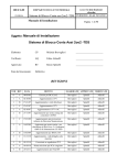
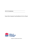
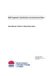
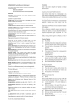
RobotEye VISION REV25 User Manual Ocular Robotics Pty. Ltd. Level 3, 12-14 Ormonde Pde Hurstville NSW 2220 Australia www.ocularrobotics.com ii Copyright Notice and Disclaimer Copyright 2013 Ocular Robotics Pty. Ltd (“Ocular Robotics”). All rights reserved. No parts of this manual may be reproduced in any form without the express written permission of Ocular Robotics. Ocular Robotics makes no representations or warranties in relation to this User Manual or the information and materials provided herein. Every precaution has been taken in the preparation of this manual to include accurate and up to date information. Ocular Robotics does not warrant that the information in this User Manual is complete, true, accurate or non-misleading. Information contained herein are subject to change without notice. Ocular Robotics assumes no responsibility for errors or omissions or any damages resulting from the use of the information contained in this handbook. Revision Table Date Notes 12/07/2011 10/04/2013 Initial Release Revision 1 www.ocularrobotics.com Ocular Robotics Pty Ltd Table of Contents iii Table of Contents Revision Table ................................................................................................................................................. ii Table of Contents .......................................................................................................................................... iii 1 Introduction ................................................................................................................................................. 1 2 Basics............................................................................................................................................................... 2 2.1 System Components .......................................................................................................................... 2 2.1.1 RobotEye VISION REV25 Unit ............................................................................................... 2 2.1.2 RobotEye VISION REV25 System ......................................................................................... 3 2.2 What You Need .................................................................................................................................... 4 2.3 Handling and Transportation ........................................................................................................ 4 2.4 Initial Setup........................................................................................................................................... 5 2.4.1 RobotEye VISION REV25 Unit ............................................................................................... 5 2.4.2 RobotEye VISION REV25 System ......................................................................................... 7 2.5 Safety ..................................................................................................................................................... 10 2.6 Operation ............................................................................................................................................. 11 2.7 Cleaning and Maintenance ............................................................................................................ 12 2.7.1 Replacement Parts ................................................................................................................... 12 3 General Description ................................................................................................................................. 13 3.1 Electrical .............................................................................................................................................. 13 3.2 Power .................................................................................................................................................... 13 3.2.1 RobotEye VISION REV25 Unit ............................................................................................. 13 3.2.2 RobotEye VISION REV25 System ....................................................................................... 13 3.3 Mechanical .......................................................................................................................................... 15 3.4 Ethernet ............................................................................................................................................... 18 3.4.1 RobotEye VISION REV25 Unit ............................................................................................. 18 3.4.2 RobotEye VISION REV25 System ....................................................................................... 18 3.4.3 Network Topology ................................................................................................................... 19 3.5 Optical ................................................................................................................................................... 21 3.5.1 Field of View ............................................................................................................................... 21 3.5.2 Camera Mounting ..................................................................................................................... 22 3.5.3 Camera Focus and Aperture ................................................................................................. 23 3.5.4 Modulation Transfer Function ............................................................................................ 23 www.ocularrobotics.com Ocular Robotics Pty Ltd Table of Contents iv 4 Specifications ............................................................................................................................................. 24 www.ocularrobotics.com Ocular Robotics Pty Ltd Introduction 1 1 Introduction IMPORTANT READ CAREFULLY BEFORE USE KEEP FOR FUTURE REFERENCE The REV25 User Manual is provided as a guide to the connection, configuration and safe use of the Ocular Robotics REV25 Vision System. For development of custom software applications for use with the REV25 system see the RobotEye Network Interface Manual, RobotEye API Reference Manual, or contact Ocular Robotics. Chapter 2 Basics, describes the initial setup and basic use of the REV25 including information on cleaning, maintenance and safety. Chapters 3 General Description presents a system description in terms of the system’s Mechanical and Electrical properties and its communication and power interfaces. CAUTION - USE OF CONTROLS OR ADJUSTMENTS OR PERFORMANCE OF PROCEDURES OTHER THAN THOSE SPECIFIED HEREIN MAY RESULT IN SIGNIFICANT RISK OF INJURY. IT WILL ALSO VOID YOUR WARRANTY www.ocularrobotics.com Ocular Robotics Pty Ltd Basics 2 2 Basics IMPORTANT – Before connecting the power to this system or attempting to operate it in any way, read and follow all instructions regarding safe operation of this system contained in section 2.5. 2.1 System Components 2.1.1 RobotEye VISION REV25 Unit Figure 2.1 – RobotEye VISION REV25 Unit Packing List The Ocular Robotics RobotEye VISION REV25 unit is supplied standard with the following components, each of which can be seen in Figure 2.1: 1. The RobotEye VISION REV25 Unit. 2. Motor Power Amplifier Board. 3. 2-Axis Motion Controller Board. 4. Installation & documentation disk. 5. Cable Harness. www.ocularrobotics.com Ocular Robotics Pty Ltd Basics 3 2.1.2 RobotEye VISION REV25 System Figure 2.2 – RobotEye VISION REV25 System Packing List The Ocular Robotics RobotEye VISION REV25 System is an RobotEye VISION REV25 Unit mounted in an IP65* enclosure with power connector and dual Ethernet connectors for RobotEye control and camera communication with the following components, each of which can be seen in Figure 2.2: 1. The RobotEye VISION REV25 System. 2. REV25 power cable. 3. Cat-5e Ethernet cable (*optional). 4. Installation & documentation disk. * To maintain the IP65 enclosure rating after installing or accessing the camera the base plate must be replaced and base plate screws correctly tensioned www.ocularrobotics.com Ocular Robotics Pty Ltd Basics 4 2.2 What You Need In order to operate the REV25 Vision unit and system, you will need: 1. Power supply – A 24 volt DC 10 Amp power supply with a continuous current capacity of 10 Amps. 2. A suitable C-mount camera – Ocular Robotics can supply and mount a range of Allied Vision Technologies GigE cameras, see the ordering info tab on the RobotEye VISION REV25 product page of the Ocular Robotics website. 3. Ethernet cable – A standard Ethernet cable (Cat5e or Cat6) is needed for control and communication with the REV25 system. 4. Camera communications cable – All cameras supplied by Ocular Robotics have a GigE communications interface. 5. A computer with a Windows or Linux operating system with one free 100 Megabit Ethernet port. 2.3 Handling and Transportation Avoid handling the RobotEye using the scanning head. This may result in mechanical damage and misalignment of the sensor. When transporting, make sure the RobotEye head will not be subject to large external loads and stresses. Figure 2.3 – REV25 Handling Zones www.ocularrobotics.com Ocular Robotics Pty Ltd Basics 5 2.4 Initial Setup NOTE – The robot eye head must be handled with extra care during transport and installation. External loads exerted on the head may result in damage. 2.4.1 RobotEye VISION REV25 Unit Follow the steps below to set the REV25 unit up for use on a computer with a Windows or Linux operating system. The library version number and system IP address shipped with your system should be noted on the supplied Certificate. Figure 2.4 Wiring and connections for the REV25 Unit 1. Connect Cable Harness (16 pin to 10/6 pin cable) between controller and amplifier board. www.ocularrobotics.com Ocular Robotics Pty Ltd Basics 6 2. Connect unit Encoder Sensor cable (14 pin connector) to black 2 Axis Motion Controller board. NOTE – Make sure the orientation of the connectors is correct. Incorrect orientations may result in damage to the system. 3. Connect motor Hall Sensor cable (8 pin connector) from the unit to the black 2 Axis Motion Controller board. 4. Connect motor power cables (4 pin white connectors) to the Motor Power Amplifier board. Match the colour coding of the connectors to ensure correct operation, incorrect connection of the motor power cables will result in uncontrolled motion of the system on power up. 5. Connect both the 2 Axis Motion Controller board and Motor Power Amplifier board to a 24 VDC power supply. Information on the polarity of the power connectors are detailed in Section 3.2. WARNING - Make sure the power supply is not powered before connecting the cables. 6. Connect one end of the Ethernet cable to the network port on the PC or switch. Connect the other end to the Ethernet port on the 2 Axis Motion Controller board. 7. Connect the chosen camera to the C-mount thread on the end of the REV25 unit. A universal camera mount to suit all Allied Vision Technologies cameras recommended for use with the REV25 product is supplied with the REV25 unit. If a different camera is chosen and it can’t be used with the mount provided then alternative mounting arrangements should be provided. DO NOT allow the camera to be unsupported on the camera lens. a) The camera lens should be rotated on the filter thread where it attaches to the REV25 by the minimum amount required to align the body of the camera to one of the two possible camera mount positions shown in Figure 3.12. b) Remove two socket head screws in the base of the REV25 body in the chosen position for the attachment of the camera mount (DO NOT have any more than two screws removed from the base of the REV25 at any time). Place the camera mount in position and replace the socket screws but do not tighten until the mount is attached to the camera. www.ocularrobotics.com Ocular Robotics Pty Ltd Basics 7 c) Use fasteners appropriate for your camera to fasten the camera to the mount and then tighten the socket screws attaching the mount to the base of the REV25 (Note – The screws used to attach the camera to the mount will need to be loosened to focus the camera). 8. Attach power and communications cables as appropriate for your camera. 2.4.2 RobotEye VISION REV25 System Follow the steps below to set the REV25 system up for use on a computer with a Windows or Linux operating system. The library version number and system IP address shipped with your system should be noted on the supplied Certificate. 1. Connect one end of the Ethernet cable to the network port on the PC or Switch. Connect the other end to the REV25 Control Ethernet port (right-side Ethernet connector). Refer to Figure 2.5. 2. Connect another Ethernet cable to the REV25 Camera Ethernet port (left-side Ethernet connector) and a PC or Switch. Figure 2.5 Wiring and connections for the REV25 System www.ocularrobotics.com Ocular Robotics Pty Ltd Basics 8 3. Make sure the 24 volt power supply is switched OFF. Connect the supplied power cable to the 24 volt power supply. On the unterminated end of the cable you will find two wires one black and one with a red sheath on it. The black wire should be connected to the negative terminal on the power supply. The cable with the red sheath should be connected to the positive terminal on the power supply. The green and yellow cable should be connected to a ground reference. WARNING - Make sure the power supply is not powered before connecting the cables. 4. Connect the power supply cable to the corresponding plug on the REV25 system. Ensure the correct orientation by aligning the polarisation keys on the panel connector and the plug. If forced in the incorrect orientation, damage to the system is likely to result. Refer to Section 3.2.2 - Power for further details. 5. If your REV25 Vision System was ordered complete with an Allied Vision Technologies camera then your system should be ready to use. For adjusting the Focus and Aperture of your camera see Section 3.5.3 - Camera Focus and Aperture. Otherwise follow steps a) to i) to install your chosen camera. a) Open the system enclosure by removing the eight countersunk socket screws from the base. b) Connect the chosen GigE camera to the C-mount thread on the end of the REV25 unit. A universal camera mount to suit all Allied Vision Technologies cameras recommended for use with the REV25 Vision product is supplied with the REV25 Vision System. If a different camera is chosen and it can’t be used with the mount provided then alternative mounting arrangements should be provided. DO NOT allow the camera to be unsupported on the camera lens. c) The camera lens should be rotated on the filter thread where it attaches to the REV25 by the minimum amount required to align the body of the camera to one of the two possible camera mount positions shown in Figure 3.12. d) Remove two socket head screws in the base of the REV25 body in the chosen position for the attachment of the camera mount (DO NOT have any more than two screws removed from the base of the REV25 at any time). Place the camera mount in position and replace the socket screws but do not tighten until the mount is attached to the camera. www.ocularrobotics.com Ocular Robotics Pty Ltd Basics 9 e) Use fasteners appropriate for your camera to fasten the camera to the mount and then tighten the socket screws attaching the mount to the base of the REV25. NOTE – The screws fastening the camera to the universal camera mount must be loosened before adjusting the focus. f) Attach the internal Ethernet cable from the enclosure camera Ethernet connector to your GigE camera g) The two pin connector shown in Figure 3.4 makes 24 VDC available for camera power connection; a suitable converter from 24V to your camera’s required voltage will need to be provided. h) Follow the procedure in Section 3.5.3 to adjust the focus and aperture of the camera. i) Replace the base using the eight countersunk socket screws and tension correctly to maintain the integrity of the seal. 6. Attach power and communications cables as appropriate for your camera. www.ocularrobotics.com Ocular Robotics Pty Ltd Basics 10 2.5 Safety The RobotEye VISION REV25 System is a high speed device. All instructions regarding safe operation of this system should be strictly followed. Protection Class 3. The device operates with a separated extra low voltage (SELV) of 24 Volts DC. The device may only be operated as intended and in faultless condition. Safety and warning signs must not be removed. The REV25 Vision System is in accordance with Ingress Protection 65 (IP65). The device is protected against dust and jet water. All instructions regarding safe operation of this system should be strictly followed. The user is responsible for the safe operation and maintenance of this system at all times. Installers of the sensor are responsible for ensuring their safe use in accordance with all applicable regulations in the state, country or territory of use. The device’s rotating head is not designed to accommodate for any alterations or additions. High speed projectiles may result. The device must be securely mounted during operation to prevent unstable motions or vibrations. Ensure that the Robot Eye head will not contact anything while operating in its full range of movement. Do not try to hold or touch the Robot Eye head while operating. Do not attempt to disassemble the sensor. Improper disassembly will destroy the optical alignment of the sensor and necessitate factory repairs. Tampering with any enclosure will void warranty coverage. The manufacturer will not accept liability for any resulting damages caused by the non-observance of this manual or any unauthorised modification to the system. www.ocularrobotics.com Ocular Robotics Pty Ltd 11 2.6 Operation Special precautions for when operating the device. The REV25 is NOT intended for use by children or inexperienced personnel. DO NOT attempt to touch or impede the Robot Eye head during operation. Avoid strands of fabric or long exposed hair from being in the vicinity of the Robot Eye head during operation. Significant injury and/or mechanical damage may result. The device must be protected from shock and impact. Figure 2.6 Do not touch RE Head while in operation. Avoid impacts. General considerations for when operating the device. The REV25 should not be put into operation when the aperture is fogged or dirty. The aperture should not be touched with bare hands. Refer to Section 2.7 for cleaning the device. The device must be protected against overheating. Persistent overheating of the device will lead to reduced lifetime of the camera. Additional protection is recommended when operating the device under extreme or adverse environmental conditions. Rapid changes in temperature may lead to humidity entering the device. www.ocularrobotics.com Ocular Robotics Pty Ltd 12 2.7 Cleaning and Maintenance CAUTION – Power must be disconnected from the REV25 system before any cleaning or maintenance is carried out. User performable cleaning and maintenance of the RobotEye REV25 Vision System is limited to cleaning of the exterior housing and the aperture window. For ANY other maintenance or repair the unit should be returned to the factory. Unauthorised opening of the system enclosure will void warranty. Use the following guidelines for cleaning of the system enclosure and aperture window. It is VERY important not to abrade or scratch the system window during cleaning or at any other time as it has the potential to significantly degrade system performance. Use a soft non-abrasive cloth to clean the window, make sure there are no foreign abrasive particles on the window before performing cleaning, as this may damage the window. DO NOT use solvents. If a cloth alone is not sufficient, water or Isopropyl Alcohol may be used. The rest of the REV25 Vision System housing can be cleaned with a soft damp cloth. 2.7.1 Replacement Parts Replacement parts can be ordered directly through Ocular Robotics. 1) RobotEye VISION REV25 System power cable. a) The power cable comprises of a standard 3 core power cable rated for at least 10A. b) The power cable has an IP68/IP69K UTS6JC103S Souriau connector attached to interface with the mating UTS6JC103P receptacle on the enclosure. 2) Cat5e/Cat6 Ethernet cable (REV25 System). a) The Cat5e or Cat6 Ethernet cable can optionally be fitted with an IP68/IP69K Souriau UTS6JC18RJN connector. 3) 5mmx20mm 16A Fuse (REV25 System). a) The fuse is located in the Schurter Fuseholder located above the left Souriau Ethernet connector. www.ocularrobotics.com Ocular Robotics Pty Ltd General Description 13 3 General Description The RobotEye VISION REV25 System is a two-axis high performance vision system with unprecedented motion bandwidth. The REV25 System is ideally suited for use on ground vehicles, surface craft, aircraft and static installations. The REV25’s embedded RobotEye technology allows applications such as inertial stabilisation, object tracking, telepresence/teleoperation, environment mapping, rapid disparate point data acquisition and persistent surveillance to be easily achieved. 3.1 Electrical The REV25 Vision System requires a 24 Volt DC power supply that has a continuous current capacity of 10 amps. The output voltage of the 24 VDC power supply used with the REV25 System should not vary by more than ±15% from the nominal 24V under any circumstances otherwise damage to the REV25 System may result. 3.2 Power 3.2.1 RobotEye VISION REV25 Unit Power is supplied to the REV25 Unit via TE Connectivity Universal MATE-N-LOK connectors as shown in Figure 3.1. Both the 2 Axis Motion Controller board and Power Amplifier board need to be directly powered by the 24 VDC supply. Figure 3.1 – Power connector on the controller and amplifier boards 3.2.2 RobotEye VISION REV25 System Power is delivered to the REV25 System with the supplied 5 metre power cable. The unterminated end of the power cable has two wires, one black and one with a red sheath on it. The black wire should be connected to the negative terminal on the power supply. The cable with the red sheath should be connected to the positive terminal on the power supply. www.ocularrobotics.com Ocular Robotics Pty Ltd General Description 14 Figure 3.2 – Power connector on the REV25 Enclosure During connection of the power supply cable to the corresponding plug on the REV25 system, ensure the correct orientation by aligning the polarisation keys on the panel connector and the plug. If forced in the incorrect orientation, damage to the system is likely to result. A 16A rated fuse is housed in the Schurter 3101-0110 fuseholder to prevent potential damage to internal electrical components from power surges. Figure 3.3 – Fuseholder on the REV25 Enclosure Power to the camera inside the enclosure is provided via a Molex KK6471 two-way connector. The red wire provides 24 VDC with respect to the black wire at 0 V. A suitable voltage converter is required if the camera operates at a different voltage. Figure 3.4 – Power connector for the camera www.ocularrobotics.com Ocular Robotics Pty Ltd General Description 15 3.3 Mechanical The REV25 Vision System has an environmental protection rating of IP65 and can operate in ambient temperatures of up to 70°C (The maximum operating temperature of installed cameras may however be lower than this) making it suitable for use in a wide range of industrial environments. The REV25 Vision Head enclosure has IP65 rating (when used with the cable socket and panel plug connectors mated). The bounding dimensions and positions of mounting holes for the REV25 Unit and System are shown in Figure 3.5 and Figure 3.6. www.ocularrobotics.com Ocular Robotics Pty Ltd General Description 16 Figure 3.5 – REV25 Unit Mechanical Dimensions www.ocularrobotics.com Ocular Robotics Pty Ltd General Description 17 Figure 3.6 – REV25 System Mechanical Dimensions www.ocularrobotics.com Ocular Robotics Pty Ltd General Description 18 3.4 Ethernet 3.4.1 RobotEye VISION REV25 Unit The REV25 Vision Unit interfaces with a computer via a standard Ethernet cable. The REV25 Control supports a 100 Megabit connection. The Ethernet connection is located on the black 2 Axis Motor Controller Board. Figure 3.7 – RJ45 Ethernet Connection located under the Serial No. label. 3.4.2 RobotEye VISION REV25 System The REV25 Vision System interfaces with a computer via a standard Ethernet cable. The REV25 Control supports a 100 Megabit connection. The REV25 Vision System has two Ethernet connections located on the side of the enclosure. The left Ethernet connector is for interfacing with the nominated imaging camera. The right Ethernet connector is for controlling the REV25 Vision System. Figure 3.8 – RJ45 Ethernet Connections on the REV25 System Enclosure www.ocularrobotics.com Ocular Robotics Pty Ltd General Description 19 3.4.3 Network Topology It is recommended that the system be used on a private network to avoid large amounts of (unwanted) data potentially being sent to all computers on the network (see Figure 3.9). Multiple REV25 Vision Units/Systems can be connected on a single network. However this should be done using a switch to avoid data collisions on the network (see Figure 3.10). The REV25 is configured to allow any number of clients to receive data when in broadcast mode. The REV25 will only accept commands from the Primary Client however. This is to ensure that multiple clients cannot simultaneously send conflicting commands to the sensor. The Primary Client is determined by the REV25 in a very simple manner, it is the client that first sends data to the REV25 after it is powered up. For a more detailed explanation of the network behaviour of the REV25 System see the RobotEye UDP Communications Specification available for download from the Ocular Robotics website. In most situations use of a Cat5e Ethernet cable will be sufficient for operation of the REV25 Vision Unit/System, however it is recommended that a Cat6 cable be used over long distances to avoid packet loss due to the large volume of data. The REV25 System enclosure has an IP68/69K rated (when used with the mating cable plug) RJ45 connectors for use when environmental conditions require the use of extra protection. The mating cable plug is a Souriau UTS6JC18RJN and can be purchased as an Ethernet cable assembly from Ocular Robotics or through various suppliers of electronic connectors. www.ocularrobotics.com Ocular Robotics Pty Ltd General Description 20 Figure 3.9 – Network Schematic for Single Host PC to Single REV25 Figure 3.10 – Network Schematic for Single Host PC to Multiple REV25’s www.ocularrobotics.com Ocular Robotics Pty Ltd General Description 21 3.5 Optical 3.5.1 Field of View The optical diagonal field of view for standard 4:3 aspect ratio CCD’s are listed in Table 1, with corresponding representations illustrated in Figure 3.11. Table 1 – Approximate Diagonal Fields of Views for standard CCD’s CCD Size Diagonal FOV 1/4” 1/3” 1/2" 2/3” 15° 22° 29° 40° Due to the nature of the optical path within the RobotEye, the 4:3 viewing rectangle will rotate within the grey aperture circle depending on the RobotEye aperture’s azimuthal position. The white circular mask inside the 4:3 viewing rectangle is a representation of the effective field of view when a non-rotating video feed/image is desired. NOTE – De-rotation of the video/image needs to be handled via software. Figure 3.11 – Field of View Representations for various CCD sizes (Not to Scale) www.ocularrobotics.com Ocular Robotics Pty Ltd General Description 22 3.5.2 Camera Mounting The universal camera mount provided with the REV25 is designed to suit all Allied Vision Technologies cameras recommended for use with the REV25 Vision Unit. If a different camera is chosen and it can’t be used with the camera mount provided then alternative mounting arrangements should be provided. DO NOT allow the camera to be unsupported on the camera lens. Unsupported cameras may result in mechanical damage. The universal camera mount can be placed in two different orientations on the mounting plate located at the bottom of the RobotEye unit as shown in Figure 3.5. The recommended mounting orientations are illustrated in Figure 3.12 below. Note that the RobotEye head in Figure 3.12 is facing the default home position (0 elevation, 0 azimuth) and that the resulting camera view will be rotated 90° with respect to horizontal for each orientation. Figure 3.12 – Recommended Camera Mounting Orientations (Forward View) www.ocularrobotics.com Ocular Robotics Pty Ltd General Description 23 3.5.3 Camera Focus and Aperture A Fujinon HF50HA-1B lens is attached to the bottom of the REV25 unit. The focal length is 50mm with an iris range of F2.3 to F22. The camera focus and aperture can be adjusted by rotating the rings on the lens as shown in Figure 3.13. Release the locking knobs to freely rotate the rings. NOTE – The screws fastening the camera to the universal camera mount must be loosened before adjusting the focus. Figure 3.13 – Fujinon HF50HA-1B C-mount Lens 3.5.4 Modulation Transfer Function The REV25 Vision optical system Modulation Transfer Function is provided below for reference. Figure 3.14 – Plot of the Modulation Transfer Function www.ocularrobotics.com Ocular Robotics Pty Ltd Specifications 24 4 Specifications Mechanical Maximum Azimuth Rate Maximum Elevation Rate Maximum Aperture Acceleration Azimuth Axis Resolution Elevation Axis Resolution Azimuth Range Elevation Range Accuracy Weight 10,000°/s 4,000°/s >50,000°/s 0.010° 0.004° 360° Continuous 70° (±35°) 0.05° 2.5 kg Electrical Communication (minimum 100 Megabit) Supply Voltage Power Consumption — Typical (average) — Maximum (peak) Ethernet 24 VDC <1.5 A 10.0 A Optical Maximum optical field of view (diagonal) Optical port 40° C-Mount Environmental Operating Temperature Range IP Class Rating (REV25 Vision System) Note: IP Rating valid only when both supplied power & optionally supplied Ethernet cable connectors are fitted. www.ocularrobotics.com -20°C - +50°C 65 Ocular Robotics Pty Ltd