1
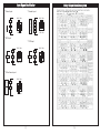
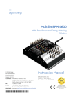
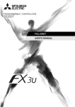
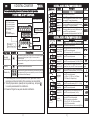
6 DIGITAL COUNTER
CR
MANUAL
D
Please understand key indicators & functions at the first operation.
GENERAL MODE OPERATING PROCEDURES
Block Charts
Mea suring Status Present value for measurement
Alarm 1
1. Press SET key, unit SV2 indicator is lighted.
Setpoint (AL1) 2. Press any number keys to modify alarm 1 setpoint,
then press SET to save the parameter.
1. Press SET key, unit SV1 indicator is lighted.
Alarm 2
Press any number keys to modify alarm 2 setpoint,
Setpoint (AL2) 2. then
press SET to save the parameter.
Press (SET)
Present Value Screen
Press (SET)
Press (SET)
Set-point Value Screen
Numbers Key
Enter Key &
Alarm Setting Key
Reset Key
Descriptions
Key Name Symbol
Enter Key &
Alarm Setting Key
1. In the measuring status, press this key can enter to alarm setting pages.
2. In the measuring status, press this key for 5 secs can enter to
parameters group.
3. In the parameter setting, press this key can save the value & go to
next parameter.
Reset Key
1. Press this key to ena ble the reset functi on.
Numbers Key
1. In the alarm setting, press each number key can increased up the digit.
2. In the parameter setting, press any number key can enter to the setting.
digit, the value will be increased up.
Initial Value
Setting (SV)
Press (SET)
1. Press SET key, unit SV indicator is lighted.
2. Press any number keys to modify initial value, then
press SET to save the parameter.
**This parameter will be appeared while “Mod” is SP-1
GENERAL MODE OPERATING PROCEDURES
Power ON
Display
Descriptions
Parameter Group Setting Procedures
Press (SET)
Press (SET)
Press (SET)
1. Press any number keys to select counting mode, then
Counting Mode press SET to save the parameter.
Setting (MOd) (SP-0: from reset value; SP-1: from initial value)
Decimal Point 1. Press any number keys to select decimal point, then
Setting (dPSV) press SET to save the parameter.
Scale Coefficient 1. Press any number keys to select scale coefficient
Decimal Point (dP-P) decimal point, then, press SET to save the parameter.
Scale Coefficient
Adjustment (P)
Press (SET)
Input Mode
Setting (OUt)
Press (SET)
Press (SET)
Press (SET)
Press (SET)
Custom ers
specify
Input Frequency 1. Press any number keys to select input frequency, then
press SET to save the parameter. (5K: 5KHz; 30:30Hz)
Setting (InCP)
1. Press any number keys to modify scale coefficient,
then pres s SET to save the param eter. (0.00 00~9.99999)
1. Press any number keys to select input mode, then
press SET to save the parameter.
(U_n: NPN up, U_P: PNP up, d_n: NPN down,
d_P: PNP down, Ud: AB phase input)
1. Press any number keys to select alarm mode , then
press SET to save the paramet er. (N, R, C, L, K, Q, A)
Alarm Mode
Setting (OUt)
Alarm Run Time 1. Press any number keys to modify alarm run time, then
Setting (tIm)
press SET to save the parameter.
Memory Hold 1. Press any number keys to select memory hold, then
press SET to save the parameter. (Yes, No)
Setting (HOd)
Press (SET)
P1
Default
Mea suring Status Present value for measurement
Press (SET) for 5sec
Press (SET)
**1. The following block charts are parameters codes, parameter codes &
parameters will alternate flashing if the parameters can be modified.
2. To modify the parameters, please press any number keys , and press
to save the parameter after the modification.
3. Please don't forget the new pass code after modification.
Default
Alarm Setpoint
FRONT PANEL & KEY FUNCTIONS
OUT1: Output 1 Indicator
OUT2: Output 2 Indicator
SV1: Set-point 1 Indicator
SV2: Set-point 2 Indicator
RUN: Working Indicator
SET: Enter Key
RST: Reset Key
1~6: Number Setting Key
Descriptions
Display
Power On
Key Lock
Setting (LCK)
1. Press any number keys to modify key lock function,
then press SET to save the parameter.
0000: all of parameters can be modified.
0001: Only LCK, SV1, SV2, SV can be modified.
0110: Only LCK can be modified.
1111: All of the functions are locked, including RST key.
P2
Custom ers
specify
Input Signal Modification
**Contact input:
Relay Output Mode Description
**Encoder Input:
NPN 5KHz
NPN 5KHz
24V
Pow
B Ph.
IN-B
A Ph.
GND
0V
24V
IN-A
IN-B
0V
PNP 30Hz
PNP 30Hz
**NPN Input:
**PNP Input:
NPN 5KHz
NPN 5KHz
24V
Sensor
24V
IN-B
Sensor
IN-B
0V
OV
PNP 30Hz
PNP 30Hz
**2 Wire Sensor Input:
NPN 5KHz
Pow
24V
IN-B
PNP 30Hz
P3
P4