1
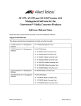
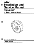
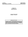
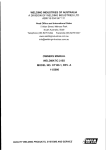
U
SER MANUAL
INSTALLATION, SERVICE and PARTS
9-N-1
Cable-Hose
Reel
ManualNumber211996
cascade”
Cascade is a RegisteredTrademarkof Cascade CorDoration
CONTENTS
1
INSTALLATION .....................................................................................................
SERVICE
SEAL AND SPRING ASSEMBLY REPLACEMENT.. ....................................
4
INNER CABLE REPLACEMENT ..................................................................
7
9
OUTER CABLE-HOSE REPLACEMENT .....................................................
TROUBLESHOOTING GUIDE ..............................................................................
11
ELECTRICAL TROUBLESHOOTING GUIDE .......................................................
12
CABLE-HOSE LENGTH CALCULATIONS ............................................................
13
PARTS LISTS.. .......................................................................................................
14-16
INTRODUCTION
This booklet contains the complete PARTS, INSTALLATION,
and SERVICE information for the 9-N-l Cable-Hose Reels. The
manual also includes TROUBLESHOOTING GUIDES located
on page 11 and 12. If you have additional questions, call the
nearest Cascade Service Department listed on the back cover.
To order replacement parts contact the Cascade Parts Sales
at:
Cascade Corporation
2201 NE 201 st
Troutdale, OR 97060-9799
Telephone: l-800-CAS-CADE
503-669-6300
Fax: 503-669-6338
211996
Rev.0
INSTALLATION
IMPORTANT: Do not allow the reel to rotate on its shaft at this
time. Doing so will prewind the spring. The wire attaching the
caution tag to the reel must stay in place until the reel is to be
prewound and cable-hose connected to the junction block.
2. Weld the mounting pad in place using a 3/16 inch fillet
weld (use E6OXX rod with no preheat or postheat) along
the vertical sides of the mounting pad only. See Figure 3.
Cover the mast hoist chains to shield from weld splatter.
1. Determine a location for the mounting pad keeping in mind
the following points:
3. Attach the reel mounting brackets to the mounting pad
using the mounting capscrews and lockwashers supplied
with the reel. See Figure 3.
a. Locate the mounting pad on the mast channel or truck
cowling. See Figure 1. The reel flanges must not
interfere with:
Figure 3
l The truck overhead guard when the mast is tilted all
the way back (if the reel is mounted on the mast).
, MOUNl ‘ING PAD
._..-.a
oThe truck carriage as it moves past the reel (if the
reel is mounted on the mast).
l The mast channel members when the mast is tilted
all the way back (if the reel is mounted on the truck
cowling).
Figure 1
CHECK CLEARANCES AT
THESE LOCATIONS WHEN
LOCATING THE REEL.
-GA
h
MOUNTING
BRACKETS
LOCKWASHER
MOUNTING CAPSCREW
Torque to 52-57 ft.-lbs.
4. Remove the fixed cover from the mounting block on the
backside of the reel. See Figure 4.
5. Join the cable connectors of the inner cable to the cable
connectors of the truck cable.
b. The inner reel flange should be no more than l/4 inch
from the side of the mast and should be placed
behind the mast channel rather than along side it. See
Figure 2.
6. Remove the clamp from the mounting block and fit it
around the truck cable. Reinstall the clamp on the reel
mounting block. See Figure 4.
c. The reel should not extend beyond the widest part of
the truck to prevent possible damage to the reel
during truck operation.
Figure 4
TRUCK CABLE
r.nNNFr-l-ARC
Figure 2
*INNER REEL
FLANGE
INNER
CABLE
CONTAINER<
INNER CABLE
CONNECTORS
/
/
*/-
/
-OUTER
REEL
FLANGE
c
. _-
-
-
t
4 7-8”
min.‘J
MOUNTING/
PAD
-MAST
CABLE TUNNEL
MAST
FRONT
*
REEL MOUNTING
BLOCKS
CHANNEL
7. Install the fixed cover on the mounting block. Tighten the
screws.
- ‘A”
J
d. If you are not using the Cascade Mounting Pad, make
sure that your pad has a thickness of at least 5/8 inch.
211996
Rev. 0
COVER
CAUTION: Overtightening
fixed cover.
the screws will damage the
8. Connect the truck valve hoses to the reel shaft.
1
9. Raise the carriage to a position approximately even with
the top of the reel. The junction block should be positioned so that it is centered between the reel flanges. See
Figure 5. Using the junction block as a guide, mark the
location of the junction block mounting holes on the back
side of the carriage. Make sure the junction block is positioned vertically.
17. Fit the cable clamps to the outer cable and secure them
as shown in Figure 7.
18. Install the rotating cover and hub nuts. The inner cable
must be laying flat in the flange depression and not
pinched. Tighten the hub nuts.
Figure 7
10. Lower the truck carriage to the floor.
11. Drill and tap both holes at the location marked on the
carriage. Figure 5 shows the diameter and drilling information for the two holes. The thread depth should be
drilled a minimum of l/2 inch.
REEL
Figure 5
HUB NUTS
Torque to 70-75
in.-lbs.
/HUB
HOSES.
FITTINGS
ROTATING
COVER
FLANGES
ZARRIAGE
JUNCTION
BLOCK
(CENTERED
BETWEEN
FEEL FLANGES)
4
Torque Capscrews
to 12-l 5 ft.-lbs.
^^.. :---A,
(if rcl”llJlJQ”,
OUTER CABLE
CONNECTORS
i
HR0003.ill
P
Flgure 8
CABLE-HOSE
REEL IDENTIFICATION
Viewed from the flange side of the reel.
12. Install the junction block on the carriage using the
capscrews and lockwashers supplied with the junction
block.
13. Determine the length of the cable-hoses required as
shown in the Cable-Hose Length Calculations, see
page 13.
NOTE: This step may be by-passed if you have been
supplied with a pre-assembled cable-hose of the correct
length.
14. Connect the hoses to the reel hub fittings. See Figure 6.
Put the end of the cable inside of the outer flange area.
RIGHT HAND REEL
LEFT HAND REEL
Hf?OOO4.ill
15. To install the outer cable-hose on the reel, remove the
two hub nuts securing the rotating cover to the outer
flange. Remove the rotating cover. See Figure 7.
16. Join the outer cable connectors to the inner cable connectors using the established connection pattern. See
Figure 7.
2
19. Wind the outer cable-hose completely onto the reel in the
direction indicated (viewed from the flange side):
Right Hand Reel: Wind cable-hose clockwise.
Left Hand Reel: Wind cable-hose counterclockwise.
A Right or Left hand reel is determined as viewed from
the flange side of the reel. See Figure 8.
211996
Rev. 0
20. Remove the caution tag and wire.
21. Prewind the reel spring by grasping the end of the outer
cable-hose and turning the reel a minimum of 3 turns in
the direction indicated (viewed from the flange side):
22. With the reel prewound, pull the hose ends down to the
junction block. Fasten the hoses with the clamp bar and
capscrew. See Figure 9.
A
Right Hand Reel: Wind reel clockwise.
Left Hand Reel: Wind reel counterclockwise.
CAUTION: Rotation in a wrong direction will damage the
inner cable and reel spring.
If more tension is required, the reel can be prewound
additional turns. The maximum turn capacities are 16
total turns.
Total turns = Prewind turns + Working turns.
CAUTION: Exceeding turn capacity of the reel will
damage the inner cable and reel spring.
WARNING: Do not let the reel unwind when
connecting the cable-hose to the junction
block.
23. Connect the cable from the cable-hose to the junction
block. Clamp the outer cable to the projection between
the hoses with a hose clamp. See Figure 9. Position the
hose clamp so it can be tightened through the hole in the
side of the junction block. Route the inner cable through
the junction block as shown. Fasten the male cable connector to the large projection with a hose clamp. Form
the hose clamp around the connectors. Do not overtighten
the clamp. The female cable connectors must fit in the
male connectors. Join the connectors.
24. Connect the attachment hoses to the junction block. Be
sure the hoses and their functions do not become interchanged. See Figure 10.
Figure 9
25. Operate the carriage up and down a few times to make
sure the cable-hose tracks smoothly and no interference
exists.
Figure 10
FUNC
Torque
to 12-l
Capscrews
5 ft.-lbs.
\
CLAMP
BAR
HR0005ill
FUNCTION A
/
HROOI O.ill
211996
Rev. 0
3
-
SEAL AND SPRING ASSEMBLY REPLACEMENT
DISCONNECTING THE REEL
Figure 12
ROTATING
COVER
1. Disconnect the cable connectors at the junction block.
INNER CABLE
HUB
WARNING: Hold hoses firmly while disconnecting cable-hose from the junction block.
Allow the reel spring to unwind slowly
while maintaining tension on the loose
-
STUD
h
. CoNNECToRS
OUTER CABLE
2. Remove the cable-hose from the junction block.
Figure 11
CABLE-HOSE
REEL
1 OUTER
f
INNER REEL
FLANGE
JWl
RIGHT HAND REEL SHOWN
STUD BRACKET
AND SPACER
LEFT HAND REEL (See Figure 8.)
LOOSE
CABLE-HOSE
END
a. Remove the hub outer snap ring. See Figure 12.
b. Pull the hub off the shaft.
HROOO6.ill
3. Remove the fixed cover from the mounting block. Disconnect the inner cable connectors from the truck cable
connectors. See Figure 4.
4. Disconnect the truck valve hoses from the shaft.
5. Remove the capscrews and lockwashers fastening the
reel to the mounting pad. Remove the reel from the mast.
REEL DISASSEMBLY
1. Remove the nuts from the hub studs and lift off the rotating cover. See Figure 12.
2. Disconnect the reel outer cable connectors from the inner cable connectors. See Figure 12.
c. Remove both flanges (with outer cable) and the stud
bracket.
7. Remove the seals from the hub. Avoid scratching grooves.
Clean the hub and shaft with solvent.
l The sealing surface on the shaft is nickel plated. If
minor surface imperfections are noted, use emery
cloth (320 Grit) to lightly smooth up. If sharp edges
or grooves are found, shaft replacement is necessary. See Figure 13.
l Hub grooves must be free of sharp nicks or projections to prevent cutting of the outside diameter of
the O-ring during installation. See Figure 13.
Figure 13
3. Disconnect the hoses from the reel hub fittings.
4. Remove the four nuts and washers attaching the inner
cable housing to the inner reel flange. See Figure 12.
5. Scribe a mark on the inner cable housing and the inner
reel flange to aid in alignment during reassembly. See
Figure 12.
6. RIGHT HAND REEL (See Figure 8.)
a. Pull both flanges (with outer cable) off the hub studs.
Rotate the flanges slightly to free the inner cable
connectors. See Figure 12.
b. Remove the hub outer snap ring.
c. Pull the hub off the shaft.
d. Leave the stud bracket and spacer on the hub.
NOTE: Since the O-rings in the hub produce friction, it
may be necessary to tap gently on the end of the shaft
with a rubber mallet or hammer handle while pulling on
the hub.
4
HR0006.ill
211996
Rev.0
SPRING ASSEMBLY REPLACEMENT
Figure 15
NOTE: If the spring assembly does not require replacement, delete this step and proceed to Reel Assembly.
1. Disengage the spring from the spring retainer on the shaft.
See Figure 14.
CAUTION: Do not allow the inner cable housing to rotate independently of its hub. Damage to the inner cable
will occur if they are rotated. Use tape or wire to hold
both from rotating. See Figure 14. If either has been rotated, refer to the Inner Cable Housing Timing instructions on page 8.
2. Hold the reel assembly, by the outside of the inner cable
housing, over a work bench with the shaft downward. Tap
the shaft end on the bench. Slide the spring assembly
out of the inner cable housing and off the shaft.
Back-up Ring
(Solid)
3. If the spring retainer has been damaged, remove the
spring retainer snap ring and install a new spring retainer.
See figure 14.
4. Slide the new spring assembly onto the shaft. Secure the
spring end on the spring retainer by turning the spring
on the shaft. Make sure the notch in the spring assembly
is aligned with the inner cable. See Figure 14.
3. RIGHT HAND REEL (See Figure 8, page 2.)
a. Rotate the hub slowly as you slide it onto the shaft.
b. Install the hub outer snap ring. See Figure 12, page 4.
REEL REASSEMBLY
1. Lubricate the shaft, seals and bore of the hub with
hydraulic oil.
2. Install the back-up rings into the hub grooves. Install the
split rings on each side of the center O-ring. Place a portion of ring in the groove, then bend as required to install.
See Figure 15. Install the O-ring seals.
NOTE: When servicing the inner cable housing or installing a new shaft seal kit, the cable harness (inside the
inner cable housing) should be lubricated with TRI-FLON
spray lube, Cascade Part No. 669779. See Inner Cable
Replacement for assembly instructions on page 7.
c. Place the reel flanges onto the hub, aligning the scribe
mark on the inner cable container to the scribe mark
on the inner reel flange.
LEFT HAND REEL (See Figure 8, page 2.)
a. With the stud bracket and spacer on the inside of the
reel flanges, slide the hub and reel flanges as one unit
onto the shaft.
b. Align the scribe mark on the inner cable housing to
the scribe mark on the reel flanges.
c. Install the hub outer snap ring. See Figure 12, page 4.
Figcwe 14
.SCRIBE
MARK
O-RINGS, SPLIT RINGS
ND BACK-UP RINGS
INNER CABLE
HOUSING
INNER
CABLE
SCRIBE
RIGHT HAND REEL SHOWN
211996
Rev. 0
MARK
(TEMPORARY)
4. Install the capscrews, lockwashers and nuts to fasten the
inner reel flange to the inner cable housing. See Figure 14,
page 5.
Figure 17
5. Reconnect inner and outer cable connectors. See Figure 16.
6. Connect the hoses to the reel hub fittings.
7. Install the rotating cover and hub nuts. The inner cable
must be laying flat in the flange depression and not
pinched. Tighten the nuts to a torque of 70-75 in.-lbs.
8. Remount the reel onto the truck.
a. Reconnect the inner cable connectors to the truck
cable at the mounting block. See Figure 4, page 1.
b. Attach the clamp to the truck cable and secure the
clamp to the mounting block. See Figure 4, page 1.
CABLE
CONNECTORS
c. Install the fixed cover.
CAUTION: Overtightening the capscrews will damage the
fixed cover.
Torque
to 12-l
9. Connect the truck valve hoses to the shaft.
\
Figure 16
HUB NUTS
Torque to 70-75
Capscrews
5 ft.-lbs.
‘CAPSCREW
CLAMP
BAR
in.-lbs.
HR0005.ill
HUB FITTINGS
ROTATING
COVER
INNER CABLE
CONNECTORS
CLAMPS
(if equipped)
-
-“--CABLE
vultn
CC-INNF
--....-CTORS
HROLXXill
10. Make sure cable-hose is tightly wound on the reel in the
direction indicated (viewed from the flange side):
13. Connect the cable from the cable-hose to the junction
block. Clamp the outer cable to the projection between
the hoses with a hose clamp. See Figure 17. Position the
hose clamp so it can be tightened through the hole in the
side of the junction block. Route the inner cable through
the junction block as shown. Fasten the male cable connectors to the large projection with a hose clamp. Form
the hose clamp around the connectors. Do not overtighten
the clamp. The female cable connectors must fit in the
male connectors. Join the connectors.
14. Connect the attachment hoses to the junction block. Be
sure the hoses and their functions do not become interchanged. See Figure 18.
15. Operate the carriage up and down a few times to make
sure the cable-hose tracks smoothly and no interference
exists.
Right Hand Reel: Cable-hose wound clockwise.
Left Hand Reel: Cable-hose wound counterclockwise.
11. Prewind the reel spring by grasping the end of the outer
cable-hose and turning the reel a minimum of 3 turns in
the direction indicated (viewed from the flange side).
Figure 16
FUNC
Right Hand Reel: Wind reel clockwise.
Left Hand Reel: Wind reel counterclockwise.
CAUTION: Rotation in a direction opposite than described
will damage the inner cable and reel spring.
If more tension is required, the reel can be prewound additional turns. The maximum turn capacities are 16 total
turns.
Total turns = Prewind turns + Working turns.
CAUTION: Exceeding turn capacity of the reel will damage the inner cable and reel spring.
12. With the reel prewound, pull the hose ends down to the
junction block. Fasten the hoses with the clamp bar and
capscrew. See Figure 16.
A
6
WARNING: Do not let the reel unwind when
connecting the cable-hose to the junction
block.
FUNCTION A ’
HROOlO.ill
211996
Rev. 0
INNER CABLE REPLACEMENT
3. Remove the fixed cover from the mounting block and disconnect the cable connectors. See Figure 4, page 1.
DISCONNECTING THE REEL
1. Disconnect the connectors at the junction block.
4. Disconnect the truck valve hoses from the shaft.
2. Remove the cable-hose from the junction block.
5. Remove the capscrews and lockwashers fastening the
reel to the mounting pad. Remove the reel from the mast.
WARNING: Hold hoses firmly while disconnecting cable-hose from the junction block.
REEL DISASSEMBLY
while maintaining tension on the loose
1, Remove the nuts from the hub studs and lift off the rotating cover. See Figure 20.
2. Disconnect the reel outer cable connectors from the
inner cable connectors. See Figure 20.
3. Disconnect the hoses from the reel hub fittings.
-HOSE
4. Remove the four nuts and washers attaching the inner
cable housing to the inner reel flange. See Figure 20.
5. Pull the reel flanges off the hub studs. Rotate the flanges
slightly to free the inner cable connectors.
6. Remove the mounting brackets and split the mounting
blocks from the shaft. See Figure 20.
7. Separate the spring assembly from the inner cable
housing. Slide the inner cable housing off the shaft. See
Figure 20.
CAUTION: Do not allow the inner cable housing to rotate independently of its hub. Damage to the inner cable
will occur if they are rotated. Use tape or wire to hold
both from rotating. If either has been rotated, refer to
the Inner Cable Housing Timing instruction on page 8.
HROO%.ill
TRUCK CABLE
CONNECTORS
rigure 20
INNER CABLE
CONNECTORS
IOTATING
COVER
OUTER CABLE
CONNECTORS
MOUNTING
SPLIT MOUNTING
INNER CABLE /
HOUSING
NUT
/
TRUCK CABLE
CLAMP
RIGHT HAND REEL SHOWN
211996
Rev. 0
I
I
7
INNER CABLE REPLACEMENT
NOTE: If a new Inner Cable Housing is being installed,
delete this step and proceed to Reel Reassembly.
1. Insert a small diameter Allen wrench under the lip of the
divider plate. Grip the Allen wrench with a pair of vise
grips. Pull outward to remove the divider plate. See
Figure 21.
5. Place the divider plate inside the housing. Push the plate
edge past the three housing indentations.
INNER CABLE HOUSING TIMING
1. Determine if the reel is a right hand or left hand model as
viewed from the flange side of the reel. See Figure 8, page
2.
2. Position the cable container with the hub cable harness
toward you. See Figure 24.
Figure 21
3. Hold the housing from rotating. Wind the hub until tight:
Right Hand Reel: Wind hub counterclockwise.
Left Hand Reel: Wind hub clockwise.
4. Rotate the hub back 1 revolution. This provides one safety
turn in the wiring to prevent internal damage.
5. Use tape or wire to secure the hub to the housing. This
will prevent either from rotating. The Inner Cable Housing is ready for further reel assembly.
Figure 24
INNER
CABLE
HOUSING
“ALLEN”
WRENCH
2. Remove the cable harness.
3. Place the new cable harness in the housing. Fit the cable
(at its 90” bend) under the spring plate and around the
pin. See Figure 22.
CLOCKWISE
ROTATION
SHOWN
Figure 22
REEL REASSEMBLY
1. Fit the new inner cable housing over the shaft (do not
rotate) and over the spring assembly. Be sure to fit the
inner cable into the notch in the spring assembly. See
Figure 20, page 7.
CAUTION: Do not allow the inner cable housing to rotate independently of its hub. Damage to the inner cable
will occur if they are rotated. Use tape or wire to hold
both from rotating. If either has been rotated, refer to
the Inner Cable Housing Timing instructions in the preceding section.
LEFT HAND REEL SHOWN
IMPORTANT: The spring assembly must be in its neutral
position when fitted into the inner cable housing.
4. Wind the cable around the hub in the direction shown in
Figure 23.
2. Install the split mounting blocks and mounting brackets.
See Figure 20, page 7.
A Right or Left hand reel is determined as viewed from
the flange side of the reel. See Figure 8, page 2.
3. Fit the reel flanges onto the hub studs. Install the
capscrews, washers, and nuts to fasten the reel flanges
to the inner cable housing.
Figure 23
HOUSING
4. Connect inner and outer cable connectors.
5. Install the rotating cover and hub nuts. The inner cable
must be laying flat in the flange depression and not
pinched. Tighten the nuts.
6. Remount the reel on the truck.
7. Reconnect the inner cable connectors to the truck cable
at the mounting block. See Figure 20, page 7.
8. Attach the clamp to the truck cable and secure the clamp
to the mounting block.
9. Install the fixed cover.
CAUTION: Overtightening
the fixed cover.
8
the capscrews will damage
211996
Rev. 0
10. Connect the truck valve hoses to the shaft.
11. Make sure the cable-hose is tightly wound on the reel in
the direction indicated (viewed from the flange side):
Right Hand Reel: Cable-hose wound clockwise.
Left Hand Reel: Cable-hose wound counterclockwise.
A right or left hand reel is determined as viewed from the
flange side of the reel. See Figure 8, page 2.
12. Prewind the reel spring by grasping the end of the outer
cable and turning the reel a minimum of 3 turns in the
direction indicated (viewed from the flange side):
Right Hand Reel: Wind reel clockwise.
Left Hand Reel: Wind reel counterclockwise.
CAUTION: Rotation in a direction opposite than described
will damage the inner cable and reel spring.
If more tension is required, the reel can be prewound additional turns. The maximum turn capacities are 16 total
turns.
Torque
to 12-l
Capscrews
5 ft.-lbs.
Total turns = Prewlnd turns + Working turns.
CAUTION: Exceeding turn capacity of the reel will damage the inner cable and reel spring.
CLAMP
BAR
13. With the reel prewound, pull the hose ends down to the
junction block. Fasten the hoses with the clamp bar and
capscrew. See Figure 25.
A
WARNING: Do not let the reel unwind when
connecting the cable-hose to the junction
block.
14. Connect the cable from the cable-hose to the junction
block. Clamp the outer cable to the projection between
the hoses with a hose clamp. See Figure 24, page 8.
Position the hose clamp so it can be tightened through
the hole in the side of the junction block. Route the inner
cable through the junction block as shown. Fasten the
male cable connectors to the large projection with a hose
clamp. Form the hose clamp around the connectors. Do
not overtighten the clamp. The female cable connectors
must fit in the male connectors. Join the connectors.
15. Connect the attachment hoses to the junction block. Be
sure the hoses and their functions do not become interchanged. See Figure 26.
16. Operate the carriage up and down a few times to make
sure the cable-hose tracks smoothly and no interference
exists.
OUTER CABLE-HOSE
1. Disconnect the old outer cable-hose from the attachment
cable at the junction block.
WARNING: Hold hoses firmly while disconnecting cable-hose from the junction block.
Allow the reel spring to unwind slowly
while maintaining tension on the loose
REPLACEMENT
Figure 27
ABLE-HOSE
EEL
LOOSE
CABLE-HOSE
END \
2. Disconnect the old cable-hose from the junction block.
3. Disconnect
Figure 27.
211996
the hoses from the reel hub fittings. See
Rev. 0
HR0007.ill
9
4. Remove the two hub nuts securing the rotating cover to
outer flange. Remove the rotating cover. See Figure 28.
Figure 29
5. Remove the cable clamps (if equipped). Discard the old
outer reel cable-hose. See Figure 28.
6. Connect the new hoses to the reel hub fittings.
Figure 29
HUB NUTS
Torque to 70-75
\
HOSES.
in.-lbs.
/HUB
v
FITTINGS
ROTATING
COVER
CONNECTORS
Torque
to 12-l
CABLE /
CLAMPS
(if equipped)
Capscrews
5 ft.-lbs.
CAPSCREW
L----l
OUTER CABLE
CONNECTORS
\
CLAMP
HR0003.ill
7. Join the new outer cable connectors to the inner cable
connectors.
8. Fit the cable clamps (if equipped) to the outer cable and
secure them on each side of the rotating cover. See Figure 28.
9. install rotating cover and hub nuts. The inner cable must
be laying flat in the flange depression and not pinched.
Tighten nuts to a torque of 70-75 in.-lbs. See Figure 28.
10. Wind the new cable-hose completely onto the reel in the
direction indicated (viewed from the flange side).
Right Hand Reel: Wind cable-hose clockwise.
Left Hand Reel: Wind cable-hose counterclockwsie.
A Right or Left hand reel is determined as viewed from
the flange side of the reel. See Figure 8, page 2.
BAR
HR0005.ill
L
13. Connect the cable from the cable-hose to the junction
block. Clamp the outer cable to the projection between
the hoses with a hose clamp. See Figure 29. Position the
hose clamp so it can be tightened through the hole in the
side of the junction block. Route the inner cable through
the junction block as shown. Fasten the male cable connectors to the large projection with a hose clamp. Form
the hose clamp around the connectors. Do not overtighten
the clamp. The female cable connectors must fit in the
male connectors. Join the connectors.
14. Connect the attachment hoses to the junction block. Be
sure the hoses and their functions do not become interchanged. See Figure 30.
15. Operate the carriage up and down a few times to make
sure the cable-hose tracks smoothly and no interference
exists.
11. Prewind reel spring by grasping the end of the outer
cable-hose and turning the reel a minimum of 3 turns in
the direction indicated (viewed from the flange side).
Right Hand Reel: Wind reel clockwise.
Left Hand Reel: Wind reel counterclockwise.
CAUTION: Rotation in a direction opposite than described
will damage the inner cable and reel spring.
If more tension is required, the reel can be prewound additional turns. The maximum turn capacities are 16 total
turns.
Total Turns = Prewind turns + Working turns
CAUTION: Exceeding turn capacity of the reel will damage the inner cable and reel spring.
A
WARNING: Do not let the reel unwind when
connecting the cable-hose to the junction
block.
12. With the reel prewound, pull the hose ends down to the
junction block. Fasten the hoses with the clamp bar and
capscrew. See Figure 29.
10
FUNCTION
A
/
HRWlO.ill
211996
Rev. 0
TROUBLESHOOTING
PROBLEM
Excessive wear on cable-hose.
Cable-Hose jumps off reel during
operation.
Cable-Hose binds during operation.
Electrical malfunction.
Cable-Hose Reel leaks at hub.
Inner Cable Housing wire
breaks inside housing.
211996
Rev.0
PROBLEM
CAUSE
GUIDE
SOLUTION
Cable-Hose reel and junction block are
not in proper alignment.
Align the junction block and cable-hose reel
properly. They must be on the same center
line and mounted squarely to each other.
See Figure 5, page 2.
Cable-Hose reel flanges damaged.
Repair or replace damaged parts.
Incorrect prewind of spring.
Prewind spring, see page 3, steps 21
through 24.
Cable-Hose not aligned with junction
block.
Align junction block with cable-hose reel.
See Figure 5, page 2.
Cable-Hose reel spring is broken.
Replace the spring.
Back-up ring in hub working
between shaft and hub.
Replace the back-up rings.
Scored seal areas.
Replace the damaged hub and/or use an
emery cloth to remove the nicks from the shaft.
The same pattern for cable connections
has not been used at all locations.
Make sure pin and cable connectors use
the same pattern at all locations.
Electrical short in the reel cable, truck
or attachment cable.
See Electrical Troubleshooting Guide, page 12.
Damaged O-ring seals in the rotating
hub.
Replace all seals. When a cable-hose reel
requires replacement of any one of the O-rings
or back-up rings, it is important that all the
seals be replaced. If all the O-rings and
back-up rings are not replaced at the same
time, the reel will only have to be disassembled again in a short period of time to
replace the older seals. The seal kit offered by
Cascade includes all of the O-rings and
back-up rings necessary to rebuild one
hose reel. Order appropriate Seal Kit.
Loose or damaged fittings.
Tighten or replace damaged fittings.
Scored seal areas.
Replace the damaged shaft and/or use
emery cloth to remove the nicks from the
shaft.
Excessive mast height.
Cable-Hose reel cannot be used in this
application. The maximum turn capacity
is being exceeded.
Cable-Hose reel wound backwards.
Replace inner Cable Housing. Wind
reel in direction indicated in Inner Cable
Housing Replacement Instructions.
Service life of wire has been exceeded.
Replace Inner Cable Housing.
11
ELECTRICAL
TROUBLESHOOTING
INNER ’
CABLE
GUIDE -
’ OUTER
CABLE
ATTACHMENT
Use the accompanying electrical diagram and the following
instructions to locate an electrical short. When using an ohmmeter to check for continuity, follow the instructions with your
meter. Make sure the electrical power is disconnected when
checking continuity.
1. Connect cable connectors A to cable connectors F (to
isolate the entire cable reel). Operate the attachment.
NOTE: Do not operate the mast.
a. If none of the attachment functions operate:
*Disconnect cable connectors
connectors F.
A from cable
@Use an ohmmeter to check the continuity of
the attachment cable (between connectors F
and G). If the cable checks OK, the truck cable
is faulty and should be replaced. Refer to your
truck Service Manual.
b. If some attachment functions respond and others do
not, the pins and/or sockets in the connectors are at
fault and should be replaced. Recheck attachment
operation after repair.
c. If all attachment functions operate correctly, reconnect
the cables as shown in the diagram and proceed to
Step 2.
12
2. Connect cable connectors A to cable connectors D (to
isolate the reel inner cable). Operate the attachment.
NOTE: Do not operate the mast.
a. If none of the attachment functions operate, the reel
outer cable is faulty and should be replaced. For replacement instructions, refer to page 9.
b. If some attachment functions respond and others do
not, the pins and/or sockets in the connectors are at
fault and should be replaced. Recheck attachment
operation after repair.
c. If all attachment functions operate correctly, reconnect
the cables as shown in the diagram and proceed to
Step 3.
3. Connect cable connectors C to cable connectors F (to
isolate the reel outer cable). Operate the attachment.
NOTE: Do not operate the mast.
a. If none of the attachment functions operate, the reel
inner cable is faulty and should be replaced. For replacement instructions, refer to page 7.
b. If some attachment functions respond and others do
not, the pins and/or sockets in the connectors are at
fault and should be replaced. Recheck attachment
operation after repair.
211996
Rev.0
CABLE-HOSE
LENGTH CALCULATIONS
-
H = Total lift height
D = Distance from centerline of
reel to junction block.
1. When H is equal to, or greater
than 2 x D, the correct cablehose length is: H - D + 38
inches
2. When H is less than 2 x D, the
correct cable length is:
D + 38 inches
Example
H = 286”
D = 96”
286” - 96” = 190” + 38” = 228”
Correct cable-hose length
HRCOl 1 .ill
CABLE-HOSE
PREPARATION
DETAIL
LENGTH (From Calculations)
REEL
JUNCTION
END
BLOCK
END
WORKSHEET
1. H = (enter mast’s lift height here)
If line 1. is equal to or larger than
line 3., the cable-hose length
should be:
H (line 1.)
2. D = (enter distance between
junction block and center of
reel with carriage completely
lowered)
- D (line 2.)
3. Multiply D by 2
+ 38 inches
4. If line 1. is less than line 3., the
cable-hose length should be:
38”
Cable-Hose Length =
D (line 2.)
+ 38 inches
38”
Cable-Hose Length =
211996
Rev. 0
13
ft.lbs.
70-75
Tighten just snug to all
hose guide to rotate.
32
B
Torque to
70-75
ft.-lbs.
LEFT HAND REEL
to
Torqu;
REELS
RIGHT HAND REEL SHOWN
CABLE-HOSE
52-57
ft.-lbs.
kLiiij+
IJu
\ ,\,il&f+
Torque to
35-40
ft.-lbs.
645990
1
1
4
28
645979
2
1
1
17
18
19
t
*
n
I
I
659890
659885
659888
3667
211569
211477
211570
659880
1 677860
659876
1 645986
65989E I
I
I
I
I
1
Bracket
l/2 NC x 5.00
Clip
Upper Mounting Bracket
Mounting
Capscrew,
Cable Service Kit - Left Hand
Connector Kit
Cable Service Kit - Right Hand
Spacer
Hub
Rotating Cover - Right Hand
Rotatina Cover - Left Hand
1
,
1
Locking Nut. l/4 NC
1
I
211475
645988
646067
211469
Left Hand
211490
646071
646070
211487
Right Hand
211476
646070
646071
211470
Left Hand
16.5” Diameter
REELS
341
36
1
1
1
1
1
1
I
I
659886
I
I
I
I
I
Reel Assembly
Caoscrew.
Kit
Riaht Hand
Service Tool Kit
Caution Tag
Divider Plate
Cable Housing Assembly - Lei Hand
Cable Housina Assemblv-
Cable Harness
Mounting
Washer, l/4 ID
Fixed Cover
Machine Screw, l/4 NC x 1.50
114 NC x .50
l/4 ID
DESCRIPTION
Lockwasher,
1 Tube
I
1
I
Nameplate
Flange
Flange
Cable-Hose
DESCRIPTION
Sockets, and Wire Seals.
211498
667898
659882
669848
669647
210294
661031
6228
659887
I
1
663886
3551
6286
2
1
1
1
I
Receptacles,
*
38
I
23 I
22 1 2
t36
n
1
21 1 4
+m37
I
I
20 1
t= 35
I
1
1
1
I
1 REF 1QTY 1 PART NO. 1
Connector Kit 211477 (Ref. No. 15) includes 3 and 6 Pos. Connectors,
Included in Cable Service Kit 211570 (Ref. No. 14).
Included in Cable Service Kit 211569 (Ref. No. 14).
Includes (1) crimping tool and (1) die set.
2
16
l
1
1
1
1
1
5
14
015
1
2
14
1 11
1
1
2
I
1 REF 1QTY 1PART NO. 1
211489
646067
645988
211486
Right Hand
14.5” Diameter
DESCRIPTION
211474
Items common to all models
211488
645990
211468
645979
211485
1
3
Left Hand
Right Hand
QTY
REF
11.5” Diameter
Items that vary according to model
CABLE-HOSE
I
I
I
I
I
HROCO2.ill
Junction Block Group
REF
1
2
3
4
5
6
7
QTY
1
1
1
1
1
1
1
NO. 6 HOSE
PART NO.
211560
659828
662139
211538
6372
4472
4468
662138
NO. 6 HOSE
PART NO.
211540
211539
662139
211538
6372
4472
4468
662138
DESCRIPTION
Junction Block Assembly
Junction Block
Clamp
Bar
Lockwasher, ,375 ID
Capscrew, .375UNCx1.50 Lg GR8
Capscrew, .375x.750 Lg
Clamp
LENGTH (From Calculations)
1
JUNCTION
REEL END
Hose-Cable Assembly
BLOCK
END
Fitting Group
HC2R, HC2L, HC6R, HC6L, HC8R, HC8L Models
646062
211564
211565
211471
211472
211473
16
646061
I
No. 8
This group includes four straight O-Ring fittings and two swivel
90” fitings. These provide hose connections into and out of the
reel. All necessary electrical connectors are included with the
reel.
211996
Rev. 0
DATE
PURCHASE
ORDER
SERIAL
NUMBER
PAGE
REF
NO
CITY
CASCADE
PART NO
CUSTOMER
PART NO
PARTS ORDERING
LOG
DESCRIPTION
PRICE
AMERICAS
Cascade Corporation
U.S. Headquarters
2201 NE 201st
Fairview, OR 97024-9718
Tel: 800-CASCADE (227-2233)
Fax: 888-329-8207
Cascade Canada Inc.
5570 Timberlea Blvd.
Mississauga, Ontario
Canada L4W-4M6
Tel: 905-629-7777
Fax: 905-629-7785
Cascade do Brasil
Rua João Guerra, 134
Macuco, Santos - SP
Brasil 11015-130
Tel: 55-13-2105-8800
Fax: 55-13-2105-8899
EUROPE-AFRICA
Cascade Italia S.R.L.
European Headquarters
Via Dell’Artigianato 1
37030 Vago di Lavagno (VR)
Italy
Tel: 39-045-8989111
Fax: 39-045-8989160
Cascade (Africa) Pty. Ltd.
PO Box 625, Isando 1600
60A Steel Road
Sparton, Kempton Park
South Africa
Tel: 27-11-975-9240
Fax: 27-11-394-1147
ASIA-PACIFIC
Cascade Japan Ltd.
2-23, 2-Chome,
Kukuchi Nishimachi
Amagasaki, Hyogo
Japan, 661-0978
Tel: 81-6-6420-9771
Fax: 81-6-6420-9777
Cascade Korea
121B 9L Namdong Ind.
Complex, 691-8 Gojan-Dong
Namdong-Ku
Inchon, Korea
Tel: +82-32-821-2051
Fax: +82-32-821-2055
Cascade-Xiamen
No. 668 Yangguang Rd.
Xinyang Industrial Zone
Haicang, Xiamen City
Fujian Province
P.R. China 361026
Tel: 86-592-651-2500
Fax: 86-592-651-2571
Cascade Australia Pty. Ltd.
1445 Ipswich Road
Rocklea, QLD 4107
Australia
Tel: 1-800-227-223
Fax: +61 7 3373-7333
Cascade New Zealand
15 Ra Ora Drive
East Tamaki, Auckland
New Zealand
Tel: +64-9-273-9136
Fax: +64-9-273-9137
Sunstream Industries
Pte. Ltd.
18 Tuas South Street 5
Singapore 637796
Tel: +65-6795-7555
Fax: +65-6863-1368
Cascade India Material
Handling Private Limited
No 34, Global Trade Centre
1/1 Rambaugh Colony
Lal Bahadur Shastri Road,
Navi Peth, Pune 411 030
(Maharashtra) India
Phone: +91 020 2432 5490
Fax: +91 020 2433 0881