1
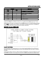
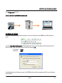
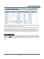
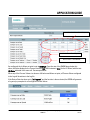
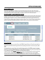
APPLICATION GUIDE AG082311 SITRANS RD500 Remote Data Management for Weighing Applications Objective: To explain the features, benefits and use of the RD500 as a remote interface, accessible from virtually anywhere an Ethernet or land Internet connection exists. Also to provide examples of configurations that allow operators the functionality of remote Zero calibrations, resetting of Totalizer(s), and the downloading of both Event and Data Log files. Equipment Description MLFB Part Number • SITRANS RD500 7ML5750-xxA000 • RJ45 Ethernet Crossover cable 7ML1930-1FM • Siemens BW500 Integrator 7MH7152-1BA0-xxxA • RS485, Shielded Twisted Pair, min 24 AWG • Industrial Compact Flash Card 1GB Communication Grade Cabling 7ML1930-1FC • 24 Volt 4 Amp DC Power Supply 6EP1332-1SH51 – Not included! • Industrial Compact Flash Card 2 GB 7ML1930-1FB • USB Cable Type A to B 7ML1930-1FN While every effort was made to verify the following information, no warranty of accuracy or usability is expressed or implied. Overview This application guide is an addition to the operating instructions. It focuses on the setup and configuration of the RD500 with a BW500 Integrator, using the Modbus communication protocol and a RS485 network connection. Please refer to both the RD500 User Manual and the BW500 User Manual for additional information. The RD500 is an easy-to-use information display and logging device that includes a configurable internal web page and flexible I/O options; it can be navigated to via an Ethernet connection or other remote means such as a GSM GPRS Hayes-compatible modem or wireless networks. In this application guide, a tag name or identifier “Conveyor xxx-xx” is referenced. In a real world application, the naming would likely be a conveyor tag number or other conveyor descriptor. There are several ways to address the RD500, depending upon your application requirements: the details of Siemens Canada Limited Siemens Milltronics Process Instruments 1954 Technology Drive, P.O. Box 4225 Peterborough, Ontario K9J 7B1 / Canada Tel.: (705) 745-2431 Fax: (705) 741-0466 www.siemens.com/sensorsystems APPLICATION GUIDE these connections are described in the RD500 technical documentation. The BW500 / RD500 connection uses the standard Modbus port; no other auxiliary equipment or options are required unless you require a wireless link. Once the BW500 and RD500 are configured, the four features that will most commonly be used for a belt scale application are: the Overview Screen, the Zero Initiate, Totalizer Reset, and the logging feature. This Application Guide defines the following procedures to effectively configure the RD500 with a BW500 Integrator: Establishing the Ethernet Link RD500 RS485 Default Settings BW500 RS485 Communication Parameters, Port #2 RS485 2-Wire Termination, BW500 to RD500 User Name and Password - Default settings Configuring the Data Logging Functions Overview Screen – Configuring the Modbus Memory Map o Process Variables o Device State o Device Control. Retrieving the Data Log files Preliminary Setup Complete and check the following actions: Review the RD500 User Manual for correct setup and operation. Set up and test the IP Address and network configuration for the RD500. Install and commission the BW500 Integrator, Belt Scale and Speed Sensor. Ensure the system is reporting accurate totalization. Establishing the Ethernet Link The Ethernet communication link to the RD500 should already be established. If the RD500 is accessed via a network, you will require the IP address assigned to the device for communication access. The following is an example of a RD500 setup on a network. The setup was performed manually using the Ethernet crossover cable and the default IP address as defined in the RD500 Manual. SITRANS RD500 Remote Data Management for Weighing Applications AG082211 2 of 17 APPLICATION GUIDE Important: Once the IP address is re-configured via the default address, communications access will only be available via the NEW IP address and network settings. If the new IP settings fail to work and communication access cannot be achieved, the RD500 can be reset via the USB utility. The “USB Type A to B” (7ML1930-1FN) cable will be required to execute the RD500 utility functions. RD500 RS485 Default Settings The RD500 RS485 port settings may not require any changes, but this is dependent on additional devices or peripherals that may be connected to the network that may require alternate settings. From the Overview Screen, follow the identified selections to navigate to the Modbus configuration table. 1. 2. 3. SITRANS RD500 Remote Data Management for Weighing Applications AG082211 3 of 17 APPLICATION GUIDE BW500 RS485 Communication Parameters, Port #2 The communication parameters for the BW500 must be set accordingly to reflect those of the RD500 settings. The BW500 is equipped with 3 communication ports, all capable of using Modbus ASCII, Modbus RTU, Dolphin Plus, & Print. We will be using the RS485, port #2 on the BW500. All parameter settings or changes must be made in Index (2) of the communication parameters. The following table reflects the parameters required to set up the BW500. Please refer to the BW500 User Manual for the correct selection for each parameter. SITRANS RD500 Remote Data Management for Weighing Applications AG082211 4 of 17 APPLICATION GUIDE Parameter Index P799 P770(2) P771(2) P772(2) P773(2) P774(2) P775(2) P778(2) Description Value 1 3 3 2 0 8 1 0 Communications Control. Modbus = 1 Modbus RTU selected Address 3 used in this example Baud Rate 9600 No Parity Data Bits 1 Stop Bit No modem attached (2) Refers to index 2 for each parameter. Configure the BW500 Port and Address settings to be compatible with the RD500 configuration. Set the Modbus address, P771 that is not already in use on the RD500: default is #1. The Modbus address is labeled as the “Node” in the Modbus device definition on the RD500. See settings display above. The BW500 will require a Power cycle for the communications port changes to take effect! RS485 2-Wire Termination, BW500 to RD500 Termination resistor: 120 ohms. If the communication link between the units is active and working, both the Red and Green LED indicator lights will be flashing. Using the RJ45 Ethernet crossover cable (7ML1930-1FM), connect the PC directly to the RD500. Configure the IP address of the PC to a Static IP address of 192.168.2.101, as long as this address is not used by the RD500. Information on the Settings can be found in the RD500 Operating Instructions Manual under SITRANS RD500 Remote Data Management for Weighing Applications AG082211 5 of 17 APPLICATION GUIDE the “Configuration” section. Default address for the RD500 is 192.168.2.100. User Name and Password To log into the RD500 through Internet Explorer, enter the IP address of the RD500 in the URL and press enter. A prompt Enter Network Password will be displayed. As long as the User Name and Password have not been changed, enter the following and continue by selecting OK. User Name: Password: admin rd500 As detailed below, the Overview screen of the RD500 interface will be unpopulated. No Process Variables will be visible. SITRANS RD500 Remote Data Management for Weighing Applications AG082211 6 of 17 APPLICATION GUIDE Configuring the Data Logging Functions To minimize additional steps throughout the setup process, a Data Log file should first be set up. This will allow immediate selection and set up of the Data Logging while configuring the Modbus Memory Map. The logging function is very useful for recording High or Low alarms for Process Variables, changes in Device State(s), or to simply log when the device has been calibrated or the Totalizers have been reset. The following screen illustrates how to effectively set up a Data Logging file. 1. From the Overview Screen, first select Configure then the Logs menu. 2. Activate the Check Box with a √ to ensure the logging file is active. 3. Enter an appropriate name for the file. This name will then be available as a selection within the Log drop-down menu when configuring Process Variables or Device States. 4. Set the interval to an appropriate selectable setting: 1 Second, 1 Minute, 15 Minute, 30 Minute, 1 Hour, 12 Hour, or 24 Hour. The interval setting will depend on the application and how often the data needs to be logged. 5. Confirm settings and configuration of the Log file by selecting Apply. 6. Refer to the RD500 Manual to determine file size and maximum number of files. The interval setting will have a direct impact on the file size and the memory capacity of the Compact Flash Card used. 7. The Data Logging function will now be available for individual selection during the configuration of the Modbus registers. 8. Then navigate back to the Overview screen to continue with the setup of the application. 9. In the example shown below, a new log file will be created every 37.5 days based on a data log every 15 minutes. SITRANS RD500 Remote Data Management for Weighing Applications AG082211 7 of 17 APPLICATION GUIDE Overview Screen – Configuring the Modbus Memory Map At this point, the Application Process Values, Status Bits, and Control Bits will have been determined. Otherwise, you can follow through with the examples provided. The following tables, also found in the BW500 User Manual, can be reviewed to determine what will be monitored and or controlled from the RD500. Please refer to the Modbus RTU/ASCII section of the BW500 User Manual for additional information regarding the Modbus Memory Map. Process Values Device State Command Control Description Process Values Device State Command Control Description 41,010 41,020 41,022 Long Word 16 Bit 16 Bit BW500 Register Type 32 Bit Long Word Bit Mapped 16 Bit Bit Mapped 16 Bit Access Read Only Access Read Only Access Read & Write Access RD500 Type LONG BIT BIT In this example, the Process Variables, Device State, and Device Control data will be programmed in the RD500 for data monitoring and logging. Identified in the following table are the Modbus registers and the required format of the registers. For each of the defined data, Process Value, Device State, and Device Control, an individual configuration is required as the register format is different for each. SITRANS RD500 Remote Data Management for Weighing Applications AG082211 8 of 17 APPLICATION GUIDE Process Value Device State Device Control Description Rate Load Speed Total 1 Total 2 Modbus Map 41,010 41,012 41,014 41,016 41,018 Format Long – 32 Bit Long – 32 Bit Long – 32 Bit Long – 32 Bit Long – 32 Bit RD500 401010 401012 401014 401016 401018 Zero Span Bit # 7 8 Bit Bit 401020 Zero Span Reset Totalizer 1 Reset Totalizer 2 7 8 9 10 Bit Bit Bit Bit 401022 To configure the Modbus mapping within the RD500, it is necessary to add an additional “0” within the register map as shown in the above table. This remains true for all configurations. The following illustrates the configured registers as required for the BW500 in this example. Configuring the Process Variables The starting Modbus register for the Process Values starting with Rate is 401010, followed by, Load, Speed, Totalizer 1 and Totalizer 2. Each of these process values is 32 bits in length (Long Word) and require two registers i.e.: Rate = 41010 & 41011. These are programmed as Type - Long, and will be configured for a length of “5” Elements, up to and including Totalizer 2, therefore the Modbus register will end at 401019. When configuring the Memory Map, enter the name (Tag ID), the Node or address of the BW500 and acknowledge by clicking on Apply. This will automatically create a new entry for the next configurable Device on the Modbus network. All configurations for Device 1 (On Node 1) will be configured via the SITRANS RD500 Remote Data Management for Weighing Applications AG082211 9 of 17 APPLICATION GUIDE Configure icon from Device 1 as shown below. Ensure the Checkbox is highlighted under Device 1 to enable the configuration in the RD500. Clicking on Configure will advance to the next screen. Enter the starting register (401010) for the Process Variables(s) to be monitored. As defined, we will be configuring the system for 5 process variables: Rate, Load, Speed, Totalizer 1 and Totalizer 2. Listed below are the appropriate settings required to configure this address for displaying the Process Variables. Please note the Elements (5), Type of Register (Long) and Access (Read Only). Once complete, acknowledge the settings by clicking on Apply. This will automatically create a new entry for the next configurable Modbus register. The following screen illustrates the settings for each Modbus register and lists them in sequential order for the specified number of Elements. For each, a Tag name is required and should reflect the appropriate address of the Modbus register, i.e: Rate, Load, etc. The View for each can be set to Yes or No; this sets what registers are displayed on the Overview Screen. For the Rate, Load and Speed registers, set the Sign to Soft Sign for correct displaying of the Process Variables. As the BW500 may realize a negative value in these registers, setting to Soft Sign will display a negative Process Value rather than an erroneous value as output from the Memory bit set. Before DP / After DP: this refers to the number of decimal places displayed for each of the Process Values SITRANS RD500 Remote Data Management for Weighing Applications AG082211 10 of 17 APPLICATION GUIDE on the RD500. The DP settings are also dependant on the configuration of the BW500. The Units field is user-configurable and should reflect the application settings of the BW500, i.e. Metric or Imperial settings. This example is set for Metric engineering units. Log: previously defined in this Application Guide, we set the Logging function active with a file name “xxxxx”. Once this has been done, the selection is available in the pull-down menu. Each of the Process Values will be logged in this example! Configuring the Device State Only 1 Modbus register is required to display the Status or Device State of the BW500. This is a Bit Mapped register. This register contains 16 bits, and each is linked to a unique function of the BW500. For this example only 2 bits will be used: Zero and Span. Note: For the Device Status and Device Control, be sure to confirm the starting bit for each. The BW500 manual lists these with a starting bit of 1, whereas the RD500 begins with a starting bit of 0. Configuring the incorrect bit may cause problems or errors within the belt scale system! SITRANS RD500 Remote Data Management for Weighing Applications AG082211 11 of 17 APPLICATION GUIDE In the far right column, the Log selection pull down menu indicates that for each of these functions, a Data Log will be generated by exception based on alarm setup. For example, the Data Log file has been configured to generate a Data Log every 15 minutes on the minute. At any given time either of these control functions can be initiated. Upon the execution of the control function, the RD500 will generate a Data Log of the configured process variables! This data log can easily be found within the file as the time stamp will most likely not take place on the pre-determined interval. Configuring the Device Control. Again, only 1 Modbus register is required for configuration of the Device Control functions. This register is designated as 401022 and again contains 16 bits, each linked to a unique control function for the BW500. For this example, 3 Device Control functions will be configured: Initiate Zero, Totalizer 1 Reset, and Totalizer 2 Reset. SITRANS RD500 Remote Data Management for Weighing Applications AG082211 12 of 17 APPLICATION GUIDE Overview Screen - Process Variables and Status Display As defined in the Modbus configuration, the Overview screen will display the pre-selected Process Variables and indicate the status of each based on the configured Alarm Set Points or Mode of Operation for the Device State. During an Alarm state, the status column will indicate a colored cell as well as a Hi-Hi, Hi, Low, or Low-Low alarm when the process variables rise above or fall below the configured set points. SITRANS RD500 Remote Data Management for Weighing Applications AG082211 13 of 17 APPLICATION GUIDE Configuring Alarm Set Points and Device Status Under the Alarms configuration screen, the High and Low Set Points can be configured according to the application requirements. In addition to the set points, a Hysteresis value can be entered to eliminate or prevent unnecessary duplication of alarm outputs or notifications should the Process Value fluctuate at or around a defined alarm set point. In addition to the Data Logging functions for the Device State and Device Control, SMS messaging and Email notifications can be configured to Send notifications based on the defined status for each from the drop-down menus. Please refer to the RD500 User Manual for configuration of SMS and email notifications. The cells or pull-down menus are used to either set a Hi or Low alarm set point, or select whether a Data log is generated based on the Status of the Device state or Device Control state. For example, if an Alarm condition or either the Zero State or Span State Status change from “Run Mode” to “In Progress”, the RD500 will generate a Data log entry for the defined Process Variables at that time. SITRANS RD500 Remote Data Management for Weighing Applications AG082211 14 of 17 APPLICATION GUIDE Alarm Set Points – Read Only Device State – Read Only Device Control – Read & Write As configured, the Lo Alarm set point is set at 30.000 tph. Once the rate of the BW500 drops below this value, the Status display for the Process Variable, rate, will illuminate in Blue (for the LO Alarm) with the text LO Alarm indicated in the same cell. See example below. When any of the Process Values rise above or fall below and Alarm set point, all Process Values configured in the Log will be written to the Log file. If the Device State has been set to “In Progress”, and the function is then activated, the RD500 will generate a log entry by exception for all configured Process Values. SITRANS RD500 Remote Data Management for Weighing Applications AG082211 15 of 17 APPLICATION GUIDE Retrieving the Data Log files The log files of the RD500 are created in comma separated variable format, CSV, which allows simple viewing using Microsoft Excel. The Data log files can be downloaded via the PC interface connection or by removing the Compact Flash card and using a card reader to view the file in Windows Explorer. Downloading the Data Log file via the Network connection From the Overview screen, select the Logs menu: this will navigate to the Logs Screen where both the Event and Data Logs can be viewed. The following screen will appear and will first list the Event Logs followed by the Data Logs. Scroll down to access or view the available data logs. By selecting the Download icon, a Standard Windows dialogue box will display the options to Open, Save or Cancel. Follow standard windows protocol to open the file with Microsoft Excel or select the Save icon to save the file to the hard drive. Compact Flash Card A data log stores its data in a series of files on the RD500's CompactFlash card. These files are placed in a subdirectory named after the data log, with this directory being stored under a root directory entry called LOGS. It is required that the compact flash card is installed during operation of the RD500 to support the logging function. To retrieve the logging files from the Compact Flash Card, simply remove the card and insert it into a Card reader and navigate to the LOGS directory within Windows Explorer. A separate Folder, named “xxx-xx” has been created and all corresponding log files can be found by date code in this folder. The date code is: YYMMDDhh.csv, where YY represents the year of the file, MM represents the month, DD represents the day and hh represents the hour. This particular logging function SITRANS RD500 Remote Data Management for Weighing Applications AG082211 16 of 17 APPLICATION GUIDE has been configured so a new file will be created at the beginning of each day starting at 12:00:00 am (0 hours). SITRANS RD500 Remote Data Management for Weighing Applications AG082211 17 of 17