1
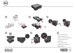
WPT
Incremental Wheel Pulse Transducer
for
acquisition of wheel rotation data
USER MANUAL
User Manual
Wheel Pulse Transducer
Notes:
© 2008 CORRSYS-DATRON Sensorsysteme GmbH, Wetzlar
WPT_m-006-e-rev001 10/08
2
User Manual
Wheel Pulse Transducer
Contents
General Information . . . . . . . . . . . . . . . . . . . . . . . . . . . . . . . . . . . . . . . . . . . . . . . . . . . . . .4
Safety Instructions . . . . . . . . . . . . . . . . . . . . . . . . . . . . . . . . . . . . . . . . . . . . . . . . . . . . . . .5
1.
Overview . . . . . . . . . . . . . . . . . . . . . . . . . . . . . . . . . . . . . . . . . . . . . . . . . . . . . . . . . . .6
2.
Extent of Delivery . . . . . . . . . . . . . . . . . . . . . . . . . . . . . . . . . . . . . . . . . . . . . . . . . . .8
3.
Technical Data . . . . . . . . . . . . . . . . . . . . . . . . . . . . . . . . . . . . . . . . . . . . . . . . . . . . . .9
3.1
Specifications . . . . . . . . . . . . . . . . . . . . . . . . . . . . . . . . . . . . . . . . . . . . . . . . . . . .9
3.2
Pin Assignments . . . . . . . . . . . . . . . . . . . . . . . . . . . . . . . . . . . . . . . . . . . . . . . . .10
3.2.1 Pin assignment: 12-pin M23 flange plug . . . . . . . . . . . . . . . . . . . . . . . . . . 10
3.2.2 Pin assignment: 8 pin M12 plug . . . . . . . . . . . . . . . . . . . . . . . . . . . . . . . . . 10
3.2.3 Pin assignment: 9-pin D-Sub socket . . . . . . . . . . . . . . . . . . . . . . . . . . . . . 11
3.2.4 Pin assignment: 3-pin Lemo . . . . . . . . . . . . . . . . . . . . . . . . . . . . . . . . . . . 11
4.
5.
Mounting and Connection . . . . . . . . . . . . . . . . . . . . . . . . . . . . . . . . . . . . . . . . . . .12
4.1
Mounting Options . . . . . . . . . . . . . . . . . . . . . . . . . . . . . . . . . . . . . . . . . . . . . . .12
4.2
Mounting Instructions . . . . . . . . . . . . . . . . . . . . . . . . . . . . . . . . . . . . . . . . . . . . .12
4.3
Connecting the sensor . . . . . . . . . . . . . . . . . . . . . . . . . . . . . . . . . . . . . . . . . . . .17
Troubleshooting . . . . . . . . . . . . . . . . . . . . . . . . . . . . . . . . . . . . . . . . . . . . . . . . . . . .18
In a continuous effort to improve our products CORRSYS-DATRON reserves the right to change specifications without prior
notice.
© 2008 CORRSYS-DATRON Sensorsysteme GmbH, Wetzlar
WPT_m-006-e-rev001 10/08
3
User Manual
Wheel Pulse Transducer
General Information
Legal Notice
Information furnished is believed to be accurate and reliable. However, CORRSYS-DATRON assumes
no responsibility for the consequences of use of such information nor for any infringement of patents or
other rights of third parties which may result from its use. No license is granted by implication or
otherwise under any patent or patent rights of CORRSYS-DATRON. Specifications mentioned in this
publication are subject to change without notice and do not represent a commitment on the part of
CORRSYS-DATRON. This publication supersedes and replaces all information previously supplied.
All brand names are trademarks of their respective holders.
Copyright Notice
©Copyright 2008, CORRSYS-DATRON
Revision
WPT_m-006-e-rev001
10/08
Contact
International Headquarters:
CORRSYS-DATRON Sensorsysteme GmbH
Charlotte-Bamberg-Str. 12
35523 Wetzlar / Germany
Phone ++49 (6441) 9282-0
Hotline ++49 (6441) 9282-82
Fax
++49 (6441) 9282-17
E-mail [email protected]
URL
www.corrsys-datron.com
North American Headquarters:
CORRSYS-DATRON Sensorsystems, Inc.
40000 Grand River, Suite 503
Novi, MI 48375 / USA
Phone ++1 (248) 615-2035
Toll-free++1 (800) 832-0732
Fax
++1 (248) 615-2184
E-mail [email protected]
URL
www.corrsys-datron.com
China Headquarters:
CORRSYS-DATRON Sensorsysteme GmbH, China Office
Room 708, JinTianDi International Mansion,
No. 998 RenMin Road, Shanghai (200021), P.R.China
Tel.: ++86-21-63114144
Fax: ++86-21-63114154
E-mail: [email protected]
URL: www.corrsys-datron.com.cn
© 2008 CORRSYS-DATRON Sensorsysteme GmbH, Wetzlar
WPT_m-006-e-rev001 10/08
4
User Manual
Wheel Pulse Transducer
Safety Instructions
Please read carefully before operating the equipment.
CORRSYS-DATRON is not responsible for damage that may occur when this system is used in
any way other than that for which it is intended.
To assure safe and proper operation, all supplied equipment, components and/or accessories must be
carefully transported and stored, as well as professionally installed and operated. Careful maintenance
and usage in full accordance with operating instructions is imperative.
CORRSYS-DATRON equipment should be installed and operated only by qualified persons who are
familiar with devices of this type.
Local regulations may not permit the operation of motor vehicles on public highways while the
equipment is mounted on the exterior of the vehicle.
• Use the equipment only for intended applications. Improper application is not advised.
• Do not modify or change the equipment or its accessories in any way.
• Improper use or mounting of the equipment may affect the safety of the vehicle and/or occupants.
• The equipment must not be mounted and/or operated in any way that may compromise vehicle
and/or occupant safety.
• Equipment must be mounted firmly and securely.
• Use only original equipment, components and/or accessories included in the scope of delivery.
• Do not use defective or damaged equipment, components and/or accessories .
• Always note correct pin assignments and operating voltages when connecting equipment to
power supplies, data acquisition/evaluation systems, and/or any other applicable system or
component. Equipment may be damaged if not properly connected and/or operated.
• For additional information, please call the CORRSYS-DATRON Hotline: ++49 (6441) 9282-82
or: [email protected]
• The sensor must be mounted with the care and accuracy that precision
testing equipment requires.
Warning
• Due to design, axial load exceeding 20 N will damage the sensor!
• Due to design radial load exceeding 40 N will damage the sensor!
• DO NOT clean any sensor component with steam!
© 2008 CORRSYS-DATRON Sensorsysteme GmbH, Wetzlar
WPT_m-006-e-rev001 10/08
5
User Manual
Wheel Pulse Transducer
1. Overview
WPT
Incremental Wheel
Pulse Transducer
for
Acquisition of Wheel
Rotation and Calculation of:
• Wheel Speed
• Distance Travelled
• Vehicle Speed
Art.no.
Wheel Incremental Transducer
11355
The CORRSYS-DATRON Wheel Pulse Transducer is a universally adaptable measuring unit for the
acquisition data derived from vehicle wheel rotation. The WPT delivers 1000 pulses per rotation (standard,
other values are possible*).
Available signals with cable version “open end”: A, A inverted, B, B inverted, Z, Z inverted (0 impulse).
Available signals with cable version “D-Sub 9”: A.
The WPT Wheel Pulse Transducer is ultra-compact and extremely light in weight. For maximum flexibility, the
incremental transducer unit of the WPT can be exchanged quickly and easily.
Output signals generated by the WPT provide the basis from which wheel rotation speed, acceleration, distance
and speed are calculated.
* on request
© 2008 CORRSYS-DATRON Sensorsysteme GmbH, Wetzlar
WPT_m-006-e-rev001 10/08
6
User Manual
Wheel Pulse Transducer
Application
The CORRSYS-DATRON Wheel Pulse Transducer is a universally adaptable measuring unit for the
acquisition of wheel rotation on vehicles and is applicable to these and other measurement applications:
• Acquisition of wheel rotation speed, distance and wheel speed
• Wheel slip measurement on passenger cars
• Acceleration and braking tests (pay attention to wheel slip)
• ABS testing
• Measurement of the difference between wheel speeds (e.g. testing of all-wheel drive vehicles)
• Special configurations available for trucks and busses
© 2008 CORRSYS-DATRON Sensorsysteme GmbH, Wetzlar
WPT_m-006-e-rev001 10/08
7
User Manual
Wheel Pulse Transducer
2. Extent of Delivery
7
8
5
1
6
4
3
2
Standard Delivery: 11355 Wheel Incremental Transducer without
mounting collets
Pos.
1.
2.
3.
4.
5.
6.
7.
8.
Art. no.
14865
14921
11968
11281
11291
15176
15178
15181
Description
Transducer, 5-30V, 1000P IP67, 8 pin.
Signal cable, 5m 8P for WPT 5-30V 9P SUB-D
Mounting hardware
Open-ended wrench 10-13
Nut driver, hexagon
Transport case, 545x405x120mm
Foam insert for transport case
Foam insert for WPT transport case
Options / Accessories
• 10070
• 10071
• 10072
Mounting collets, 17 mm (standard)
Mounting collets, 19 mm (standard)
Mounting collets, 21 mm (standard)
Other sizes available upon request.
•
•
•
•
11296
11297
11298
10036
Centering stars, 5-lug
Centering stars, 4-lug
Centering stars, 3 lug
Suction cup for fixing the safety line
•
•
•
•
14897
14898
14915
15083
Signal
Signal
Signal
Signal
cable
cable
cable
cable
5m 8P WPT IP67 open end
10m 8P WPT IP67 open end
5m 8P WPT 3P Lemo
10m 8P WPT 5-30V 9P SUB-D
© 2008 CORRSYS-DATRON Sensorsysteme GmbH, Wetzlar
WPT_m-006-e-rev001 10/08
8
User Manual
3.
Technical Data
3.1
Specifications
Wheel Pulse Transducer
Characteristic Mechanical Values
Max. permissible rotational speed
6000 min-1 (continuous operation 3000 min-1)
Available pulse values
Standard: 1000 pulses/rotation,
10 to 3600 pulses/rotation on request
System protection
IP 67
Operating temperature range
-40° C ... +85° C
Shock resistance
2500 m/s2, 6 ms
Vibration resistance
100 m/s2, 10 ... 2000 Hz
Characteristic Electrical Values
Output circuit
RS-422
(TTL compatible)
Push-pull circuit
Power supply, UB
5 ... 30 V DC
10 ... 30 V DC
Power consumption,
signals inverted, without load
type 40 mA /
max. 90 mA
type 50 mA /
max. 100 mA
Permissible weight/channel
max. ±20 mA
max. ±20 mA
Pulse frequency
max. 300 kHz
max. 300 kHz
Signal level, high
min. 2.5 V
min. UB - 1V
Signal level, low
max. 0.5 V
max. 0.5 V
Rising and falling time
max. 200 ns
max. 1 μs
Reverse polarity protection
of the power supply
yes
yes
Short circuit-proof outputs
max. 1 channel
could be short-circuited
yes
Output signal
2 channels, A and B, 90° shifted,
1 zero impulse per rotation, all signals
with inversion
Plugs
12 pin M23 or 8 pin M12 plug
radial flange connector on the housing,
pins separately sealed, IP 67 in unplugged condition
© 2008 CORRSYS-DATRON Sensorsysteme GmbH, Wetzlar
WPT_m-006-e-rev001 10/08
9
User Manual
3.1
Wheel Pulse Transducer
Pin Assignments
3.2.1 Pin assignment: 12-pin M23 flange male plug - sensor connector
WPT Art.no. 14375
Pin
Pin
Pin
Pin
Pin
Pin
Pin
Pin
1
2
3
4
5
6
7
Signal
Pin
Signal
Signal B inverted
+UB Sensor *
Zero pulse
Zero pulse inverted
Signal A
Signal A inverted
n.c.
Pin 8
Pin 9
Pin 10
Pin 11
Pin 12
Shield
Signal B
n.c.
0 V (GND)
0 V Sensor *
+UB
on the housing
* Sensor leads are internally connected to the power supply and can be used with extension
cables for power adjustment or regulation of the transducer.
If sensor leads are not used, they must either be isolated or connected 0 V Sensor with 0V and UB
Sensor with UB.
On type RS 422 the lead end must be covered with a corresponding shaft resistor when extension cables are used.
Unused outputs must be isolated prior initial operation.
Cables:
A. Signal Cable K-006-130-20-5m female
B. Signal Cable K-006-130-10-5m female
9 pin D-Sub
Part.no. 10465
A. Power supply UB = 5 VDC
9 pin D-Sub
Part.no. 10464
B. Power supply UB = 10 ... 30 VDC
Pin
Signal
Pin
Signal
Pin 1
Pin 2
Pin 3
Pin 4
Pin 5
Pin 6
Pin 7
Pin 8
Pin 9
Shield
1 kΩ against Pin 5 and Pin 7 each
Signal A
n.c.
n.c.
0V (GND), 1 kΩ against Pin 1
n.c.
+UB (5 VDC), 1 kΩ against Pin1
n.c.
n.c.
on housing
Pin 1
Pin 2
Pin 3
Pin 4
Pin 5
Pin 6
Pin 7
Pin 8
Pin 9
Shield
Bridge to Pin 7
Signal A
n.c.
+UB (10 ... 30 VDC),
0V (GND)
n.c.
Bridge to Pin 1
n.c.
n.c.
on housing
3
2
3 pin Lemo
Part.no. 10466
1
© 2008 CORRSYS-DATRON Sensorsysteme GmbH, Wetzlar
C. Signal Cable K006.52.51
Pin
Signal
Pin 1
Pin 2
Pin 3
Signal A
GND
+12V
WPT_m-006-e-rev001 10/08
10
User Manual
Wheel Pulse Transducer
3.2.2 Pin assignment: 8 pin M12 male plug - sensor connector
WPT Art.no. 14865
Pin
Pin
Pin
Pin
Pin
Pin
Pin
Pin
Pin
Signal
1
2
3
4
5
6
7
8
GND
+UB
Signal A
Signal A inverted
Signal B
Signal B inverted
0 imp
0 imp inverted
Cables:
A. Signal Cable K-006-181-20-5m female
9 pin D-Sub
Part.no. 14921
A. Power supply UB = 5 ... 30 VDC
Pin
Signal
Pin 1
Pin 2
Pin 3
Pin 4
Pin 5
Pin 6
Pin 7
Pin 8
Pin 9
Shield
Bridge to Pin 7
Signal A
n.c.
+UB (5 ... 30 VDC),
0V (GND)
n.c.
Bridge to Pin 1
n.c.
n.c.
on housing
3
2
B. Signal Cable K-006-181-30-5m
3 pin Lemo
Part.no. 14915
1
Pin
Signal
Pin 1
Pin 2
Pin 3
Signal A
GND
+12V
© 2008 CORRSYS-DATRON Sensorsysteme GmbH, Wetzlar
WPT_m-006-e-rev001 10/08
11
User Manual
Wheel Pulse Transducer
4. Mounting and Connection
4.1 Mounting Options
The Wheel Pulse Transducer mounts to the wheel lug nuts via adjustable mounting collets. The torsional
protection rod (which maintains rotation around the wheel axis) is affixed to the vehicle body with suction
holders.
• Mounting disk:
Fits 3-, 4- and 5-lug rims
• Mounting collets:
Standard: 17, 19, 21 mm (other sizes available upon request)
• Centering stars:
3-, 4- and 5-fold star, optional
• Torsional mounting:
Joints, guide rod, suction holder, gaiter seals
4.2 Mounting Instructions
1. Select the following parts:
Mounting collets
Retainer screws with washers
Nut driver, hexagon
Mounting disk
Fig. 1
2. Remove hubcap or any covering over wheel nuts and
clean dirt/debris from wheel nuts.
Remove the retainer screws from the top of each collet,
then place the mounting collets firmly on the wheel nuts.
Mounting collets
Fig. 2
© 2008 CORRSYS-DATRON Sensorsysteme GmbH, Wetzlar
WPT_m-006-e-rev001 10/08
12
User Manual
Wheel Pulse Transducer
3. Align the mounting disk with the collets and affix it with
retainer bolts and washers. Do NOT fully tighten the
bolts at this step!
NOTE: Each mounting slot on
the disk is marked to ensure
proper alignment with 3-, 4-,
and 5-lug configurations.
ATTENTION: The lobe of
the washers (Fig.3b) must
show towards the collets!
Fig. 3b
Fig. 3a
4. A rough centering of the mounting plate can be achieved by
slight rotation in clockwise direction.
Fig. 4
5. If you use centering stars for mounting, select the centering
star
that
corresponds
to
the
lug
configuration (3x, 4x, or 5x) of the wheel on which the
sensor will be mounted. (Fig. 5 shows 5-fold star)
NOTE: Each centering star is fitted with nylon knobs,
which facilitate positioning and serve as leverage points.
Positioning
knobs
Fig. 5
6. Slide the centering star onto the mounting disk hub
and rotate the centering star so that its edges press firmly
against the collet retainer washers. Then, apply
pressure to the positioning knobs on the centering star,
as shown, and tighten one of the bolts using a 5 mm hex
nut driver. This will ensure that the mounting disk is
properly centered on the wheel.
Fig. 6
© 2008 CORRSYS-DATRON Sensorsysteme GmbH, Wetzlar
WPT_m-006-e-rev001 10/08
13
User Manual
Wheel Pulse Transducer
7. Continue to hold the centering star tightly against the
mounting washers, then tighten the mounting bolts in a
cross pattern. The deviation of concentricity should be
within 0.2 mm (see page 18, Signal errors due
to incorrect mounting).
Fig. 7
8. Select the following parts:
A. Transducer with mounting plate
B. Transducer mounting bolt
C. Suction mount
D. Torsion mounting assembly
E. Extension rod
Fig. 8
9. If the transducer mounting plate is not already
mounted to the transducer, slide the plate onto the
back of the transducer as shown in Fig. 9 and
secure it by tightening the set screw.
A
A. Transducer mounting plate
B. Transducer
B
C
C. Set screw
Fig. 9
© 2008 CORRSYS-DATRON Sensorsysteme GmbH, Wetzlar
WPT_m-006-e-rev001 10/08
14
User Manual
Wheel Pulse Transducer
10. Slide the transducer mounting bolt through the
hole at the center of the transducer, then thread the
bolt into the hole at the center of the mounting hub.
Tighten the bolt securely using the knob.
Transducer
Knob on short mounting bolt
Fig. 10
11. Some vehicle body configurations may require the use
of the spacer shown in Figure 11a/11b in order to
mount the torsion assembly parallel to the vehicle. The
spacer is placed between the mounting disk and the
transducer. When using the spacer, it is necessary to
use the long transducer mounting bolt.
Axial load exceeding 20 N / radial load
exceeding 40 N will damage the sensor!
Danger
Long mounting bolt
Spacer
Fig. 11a
ATTENTION: The slot of the spacer must be
directed towards the Sensor!
spacer slot
Fig. 11b
12. Measure or visually estimate the distance from the top
of the transducer mounting clamp to an area of the
vehicle body onto which the suction holders can be
attached.
Next, select either or both of the two extension rod
sections and configure the assembly to the required
length. Each rod has a threaded female end and a
threaded male end. This allows the rods to be fitted
together, as well as into the main section of the torsion
assembly.
If multiple sections are required, tighten them together by
hand, then slide a small screwdriver (or similar tool of
appropriate diameter) into the small holes near the the
ends of the extension rods. Using the screwdrivers for
leverage, tighten the sections together firmly (use
caution to avoid stripping the threads).
Then, screw the extension rod(s) into the threaded
female receptacle at the top of the mounting plate as
shown in Figure 12 and tighten.
© 2008 CORRSYS-DATRON Sensorsysteme GmbH, Wetzlar
Fig. 12
Extension rod(s)
Top of mounting plate
WPT_m-006-e-rev001 10/08
15
User Manual
Wheel Pulse Transducer
13. Loosen the cap at the bottom end of the gaiter that
protects the mounting assembly. Then, slide the gaiter
back to enable access to the threaded end of the rod.
Protective gaiter
Gaiter cap
Fig. 13
14. Screw the main section of the torsion assembly into the
top of the extension rod(s) and tighten.
Slide the protective gaiter back over the threaded joint
and re-thread the cap, but do not fully tighten it at
this step (see step 17, page 17).
Press the suction holders firmly against the vehicle body
and latch the suction holder lock handles as shown in
Figure 14 (latched position is approximately parallel to
vehicle body surface).
When the suction holders produce an effective
vacuum, you will feel a distinct resistance.
Fig. 14
ATTENTION: To assure proper function of the suction
holders, the mounting area must be free of grease, oil,
dust and other contaminants. For this reason it its
necessary to clean the painted surface in the mounting
area before attaching the suction holders. Do not use
cleaning products that leave residue of any kind on the
surface.
15. Plug the signal cable into the transducer and tighten
the connector.
Fig. 15
© 2008 CORRSYS-DATRON Sensorsysteme GmbH, Wetzlar
WPT_m-006-e-rev001 10/08
16
User Manual
Wheel Pulse Transducer
16. Wind the signal cable loosely around the torsion rod
and secure with a cable tie.
WARNING: Be sure to leave enough slack
in the cable to allow for suspension travel,
but use caution to assure that the cable is
Danger not wound too loosely around the torsion
bar. Under no circumstances should the
cable be loose enough to touch the tire or to
be pulled under the fender during testing.
Either circumstance would inevitably result
in damage to the equipment and could also
cause an accident.
Fig. 16
17. Slide the protective gaiters over the lower and upper
sections of the torsion rod assembly and tighten the
caps. Then, secure the safety line to the vehicle.
In Figure 17, the safety line is tied to an optional
suction cup.
Danger
B
E
D
C
The safety line should always be used to
avoid damage or injury in the event that a
suction holder separates from the vehicle
body during the test drive.
A
A. Suction cup
B. Cap
C
C. Gaiter
D. Safety line
E. Optional suction cup
B
Fig. 17
4.3 Connecting the Sensor
Finally, connect the signal cable to data acquisition. When using other than CORRSYS-DATRON data
acquisition systems, make sure that the polarity of the sensor supply is correct and the data acquisition
supplies the sensor-specific current and signal conditions.
© 2007 CORRSYS-DATRON Sensorsysteme GmbH, Wetzlar
D006-50-02-04E
06/07
17
User Manual
Wheel Pulse Transducer
5. Troubleshooting
When troubleshooting the CORRSYS-DATRON Incremental Wheel
Pulse Transducer, begin by checking the following:
Cables and power supply
• Check all connections to determine that each is complete and that the system is connected to
a power supply that provides voltage output within the specified range.
• Check to determine that the correct cables have been used for all connections.
• The following problems can be caused by incorrect or incomplete cable connections and/or
connection to incorrect power supply voltage:
- A sensor will not show any signal with vehicle motion.
Signal errors due to incorrect mounting
• Make sure that the sensor is mounted parallel to the wheel.
• The deviation of concentricity should be within 0.2 mm (see Step 7 on page 14).
• Please see that the torsion mounting assembly is adapted to the vehicle type (suspension travel).
• Do not exceed the maximum rotational speed of 3000 RPM or 250 kph.
If none of the above recommendations provides a solution, please contact us.
CORRSYS-DATRON Hotlines:
CORRSYS-DATRON Hotline: ++49 (6441) 9282-82 or: [email protected]
CORRSYS-DATRON Servie-Hotline: ++49 (6441) 9282-29 or: [email protected]
© 2008 CORRSYS-DATRON Sensorsysteme GmbH, Wetzlar
WPT_m-006-e-rev001 10/08
18