1
RE-Series
Diode-Pumped Nd:YAG Rod Laser Modules
Models RE-50, RE-63, & RE-70
User Manual
i
RE-Sereis Diode-Pumped
Nd:YAG Rod Laser Module
Instruction Manual
Cutting Edge Optronics
20 Point West Boulevard
Saint Charles, MO, 63301
CEO-UMAN-0006
Rev. Q
October 2007
ii
Preface
This manual describes the installation, operation, and service of the RE-Series module.
The RE-Series module emits laser radiation that can permanently damage eyes and skin, ignite fires, and
vaporize substances. The Laser Safety section (Chapter 2) contains information and guidance about these
hazards. To minimize the risk of injury or expensive repairs, carefully follow these instructions.
The Service and Repair section is intended to help guide you to the source of problems. Do not attempt
repairs while the unit is under warranty; instead, report all problems to Northrop Grumman Space
Technology Cutting Edge Optronics (NGST CEO) for warranty repair.
We welcome your comments on the content and style of this manual. The last page is a form to aid in
bringing your thoughts to our attention. Thank you for your purchase of NGST Cutting Edge Optronics
components.
Do not open the factory packaging before carefully reading this complete operation and
maintenance manual. If you have any questions on the product which have not been discussed sufficiently
within the manual, contact the manufacturer for complete instructions. Failure to heed this warning may
result in the destruction or serious damage to the device, and will void the product warranty.
iii
Table of Contents
Preface...................................................................................... iii
Table of Contents......................................................................iv
SI Units......................................................................................vi
Acronyms ................................................................................. vii
Chapter 1
Introduction.......................................................... 1
Theory of Operation........................................................................................................................................................1
Temperature Tuning of Laser Diodes...........................................................................................................................2
RE-Series Description .....................................................................................................................................................3
Closed Loop Re-circulating Chiller................................................................................................................................4
Specifications1 ...................................................................................................................................................................4
Chapter 2
Laser Safety .................................................. 6
Caution & Warning Statements......................................................................................................................................6
Precautions for Safe Operation of Class IV Lasers .................................................................................................7
Center for Devices and Radiological Health (CDRH) OEM Product.....................................................................8
Key to Radiation Control Drawing................................................................................................................................9
Safety Device Checklist ...................................................................................................................................................9
Chapter 3
Operation.................................................... 10
Unpacking your Module................................................................................................................................................10
RE-Series Module...........................................................................................................................................................10
Closed Loop Chiller .......................................................................................................................................................14
Chapter 4
Installation and Operation................................ 19
RE-Series Laser Module Assembly and Connections...............................................................................................19
Closed Loop Water Chiller Assembly .........................................................................................................................21
Starting the Laser System ..............................................................................................................................................22
Pre-start Conditions .......................................................................................................................................................22
Turning On The Laser System .....................................................................................................................................22
Powering the RE-Series Module ..................................................................................................................................23
Standby Condition..........................................................................................................................................................23
Turning Off the System.................................................................................................................................................24
Chapter 5
Maintenance ................................................... 25
Rod Cleaning...................................................................................................................................................................25
Adjusting the Operating Current .................................................................................................................................25
Cleaning the Chiller........................................................................................................................................................26
Chapter 6
Service............................................................... 27
Rod Cleaning...................................................................................................................................................................27
Rod Removal and Replacement ...................................................................................................................................27
Leak Test Procedure ......................................................................................................................................................29
Chapter 7
Return for Repair ............................................... 30
Return of the Instrument for Repair ...........................................................................................................................30
Warranty...........................................................................................................................................................................30
Disposal ...........................................................................................................................................................................30
ROC ROHS Declaration...............................................................................................................................................31
iv
v
SI Units
The following System International (SI) units, abbreviations, and prefixes are in Cutting Edge Optronics
(CEO) manuals:
Quantity
Mass
Length
Time
Frequency
Force
Energy
Power
Electric Current
Electric Charge
Electric Potential
Resistance
Inductance
Magnetic Flux
Magnetic Flux Density
Luminous Intensity
Temperature
vi
Unit
gram
meter
second
Hertz
Newton
Joule
Watt
Ampere
Coulomb
Volt
Ohm
Henry
Weber
Tesla
candela
Kelvin
Abbr.
g
m
s
Hz
N
J
W
A
C
V
W
H
Wb
T
cd
K
tera
giga
mega
kilo
deci
centi
milli
micro
nano
pico
femto
atto
Prefixes
(1012)
(109)
(106)
(103)
(10-1)
(10-2)
(10-3)
(10-6)
(10-9)
(10-12)
(10-15)
(10-18)
T
G
M
k
d
c
m
µ
n
p
f
a
Acronyms
The following acronyms are used in this manual:
ACGIH
ANSI
AR
AO
CDRH
CEO
CFR
CW
DC
EO
ESD
FET
FDA
FWHM
GaAlAs
GPM
HR
HV
IR
KTP
LBO
MCC
Nd:YAG
NGST
NIR
OSHA
PRF
PSI
SHG
TTL
VAC
vii
American Council of Government Industrial Hygienists
American National Standards Institute
Anti-Reflective
Acusto-Optical (type of Q-switch)
Center for Devices and Radiological Health - U.S. Food and Drug Administration
Cutting Edge Optronics, Incorporated
Code of Federal Regulations
Continuous Wave
Direct Current
Electro-Optical (type of Q-switch)
Electro-Static Discharge
Field Effect Transistor
U.S. Food and Drug Administration
Full Width - Half Max
Gallium Aluminum Arsenide
Gallons Per Minute
High Reflector
High Voltage
Infrared
Potassium Titanyl Phosphate
Lithium Triborate
Meters Concave
Neodymium-doped Yttrium Aluminum Garnet
Northrop Grumman Space Technology
Near Infrared
Occupational Safety and Health Administration
Pulse Repetition Frequency
Pounds per Square Inch
Second Harmonic Generator
Transistor - Transistor Logic
Volts, Alternating Current
Chapter 1
Introduction
The RE-Series module was designed for use as a building block “engine” in the development or production
of medium power rod laser systems or as a drop-in replacement for arc lamp pump chambers in industrial
lasers. It is well suited for medium power applications such as laser marking, and can provide high stability
and beam quality for more precise micro-machining and scientific applications.
Theory of Operation
Northrop Grumman Space Technology Cutting Edge Optronics (NGST
CEO) diode pumped, solid-state lasers and pump modules use temperaturetuned GaAlAs laser diodes. These diodes replace arc lamps or incandescent
light sources as the optical pump source. The principal advantages of this
approach include:
• Longer lifetime
• More compact size
• More efficient operation
The RE-Series module uses arrays of solid-state laser diodes to optically pump
a neodymium-doped yttrium aluminum garnet (Nd:YAG) lasing medium. The
diode optical output power is radially coupled into the laser rod. The Nd:YAG
laser rod has an anti-reflection coating chosen for the highest gain wavelength
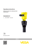
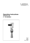
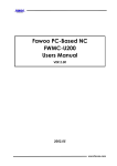
of this material, 1064 nm. The RE-Series module is constructed within a
durable and rigid structure. Exterior components and connections are shown
in Figure 1.
Coolant Port
Rod
Electrical Contact
Hour Counter
Figure 1 Exterior Components and Connections
1
Temperature Tuning of Laser Diodes
The laser diodes are located within the RE-Series module and tuned,
wavelength matched, via the closed loop chiller. For maximum efficiency, the
diode output wavelength must match the laser medium absorption
characteristics (see Figure 2). The output spectrum of a conventional pump
source for Nd:YAG operation, the xenon arc lamp, and 808 nm diode array is
also shown.
Figure 2 Nd:YAG Absorption Characteristics
A single GaAlAs laser diode bar has a 2 nm FWHM distribution of output
wavelengths. However, the process used in the manufacture of GaAlAs laser
diodes results in a peak output wavelength for each diode that fits within a 10
nm distribution of wavelengths from 800-810 nm. To match the diode output
to an absorption peak of the laser medium, diodes are selected with similar
peak output wavelengths within the manufacturing range. Temperature tuning
is possible because GaAlAs diode characteristics are such that 0.25 nm of
wavelength shift occurs for every 1oC change in temperature of the diode
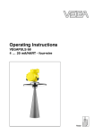
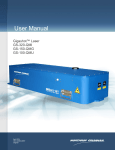
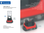
junction. Cooling shortens the wavelength, and heating lengthens it. Figure 3
shows the percentage of pump light of different wavelengths absorbed by two
passes through a 6.35 mm thick rod of 0.6% doped Nd:YAG. In CEO
modules, the laser diode center wavelength, under normal operating
conditions, is near the absorption peak of the laser medium. The operating
temperature of closed loop chiller is carefully chosen to shift the diode
temperature, so that the wavelength matches the absorption peak. The final
test report, included with each module, indicates the optimum operation
temperature for that module.
2
Figure 3 Pump Light Absorption vs. Pump Array Center Wavelength
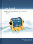
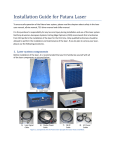
RE-Series Description The RE-Series module utilizes a radial transverse pump geometry to excite the
solid-state laser medium (see Figure 4). This pump geometry results in excellent
gain uniformity and lensing performance. The reflector directs the divergent
diode light back to the laser medium, which is kept in a flow tube for coolant
circulation. The laser medium is a rod of neodymium-doped yttrium aluminum
garnet (Nd:YAG). Both ends of the rod are optically polished and include anti
reflection coatings at the lasing wavelength. The ends of the Nd:YAG rod may
be curved to compensate for thermal lensing, depending on module
configuration.
Figure 4 Radial Pump Geometry
The five diode arrays that radially pump the rod can each have one or two
parallel lines of diode bars. The single line version is called the 1C2 in CEO
literature, while the double bar version is called the 2C2. Naturally, the double
3
bar (2C2) version requires twice the diode bias voltage and twice the input
power of the single bar version of the pumphead.
The laser medium is a 146 mm long rod of neodymium-doped yttrium
aluminum garnet (Nd:YAG). The rod is 5 mm diameter for RE-50, 6.35 mm
for RE-63, and 7 mm in RE-70. Both ends of the rod are optically polished
and include anti reflection coatings at the lasing wavelength. The Nd:YAG rod
ends are curved to compensate for thermal lensing, unless otherwise requested.
Closed Loop Re-circulating Chiller
Coolant flow direction is polarized on the RE-Series pump module. Inlet and
Outlet hose barbs are marked on the pumphead. Be sure to connect the
coolant filter for the selected chiller on the Inlet connection, so only clean
coolant from the filter flows through the pumphead. Dirty coolant deposits
dirt on the Nd:YAG rod, which results in low output power.
The module coolant loop is designed for an operating pressure of 50 psi.
Chillers which deliver the required flow rate at lesser pressure do not provide
adequate cooling. The selected chiller must have a heat capacity of greater than
the power consumption for the specific model of RE-Series module.
CEO recommends different model of chiller depending on the number of
diode bars in a module and the local electricity which will power the chiller.
The following table (figure 5) gives the CEO recommendations.
60 Hz Electrical Outlets
EOL
Model
Current
REXX-1C2
32 A
REXX-2C2
32 A
Waste
Heat
2304 W
4608 W
Polyscience
Chiller No.
6160T11CE30D
6860T56CE70D
Chiller
Capacity
2900 W
5200 W
50 Hz Electrical Outlets
EOL
Waste Polyscience
Model
Current
Heat
Chiller No.
REXX-1C2
32 A
2304 W 6150T21CE30E
REXX-2C2
30 A
4320 W DCA206D1FF
Figure 5 CEO Recommended Chiller Table
Chiller
Capacity
2407 W
5810 W
Specifications1
RE-Series modules are tested to exceed the following specifications. The
standard production test configuration consists of a 280 ± 5 mm cavity
utilizing a flat high reflector and a flat 70% reflective output coupler.
4
Model
Output Power (W)
Rod Diameter (mm)
Diode Bias Voltage @ 27
A (VAC)
Power Consumption (W)
RE501C2
200
5
RE631C2
2C2
200
450
6.35
6.35
RE701C2
2C2
200
450
7
7
72
72
144
72
144
2810
2810
5600
2810
5600
All RE-Series Models
Type
CW Diode Pumped Nd:YAG Rod4
Standard Dopant
0.6%
Output Wavelength
1064 nm
Polarization
Random
Cooling
Closed Loop Recycling Coolant5
Coolant Flow
> 2.0 GPM
6
Coolant Pressure
50 PSI
Operating Temperature
20-30 oC non-condensing
Optical Center from Base
1.50 inches
Module Dimensions (inches)
2.81 H x 2.62 W x 6.75 L
Nominal Weight
4.4 lbs.
eDrive Dimensions (inches)
3.48 H x 19 W x 17.65 D inches
Figure 6 RE-Series Specifications Tables
1. Specifications subject to change without notice
2. Output power from the production test cavity (280 mm ± 5 mm cavity utilizing a flat HR
and flat 70% reflective output coupler)
3. At end of life [(Operating current x Diode voltage) x 130%]
4. The Continuous Wave (CW) diode arrays are sensitive to excessive thermal cycling. Current
should not be turned off completely and then restored to full operating current more than 6
times per day. Current should be gradually (~1A/s) ramped up when operating current
restored. See chapter 3 for more details.
5. CEO recommends Purelase 180 coolant.
6. CEO modules are leak tested to 60 psi with Nitrogen gas. CEO recommends 50 psi of
chiller water for actual operation.
5
Chapter 2
Laser Safety
Please read this section carefully before installing or operating your RE-Series module. We recommend that all
service and repair operations be performed by a NGST Cutting Edge Optronics service engineer. If you do
plan to service your laser module, please follow the procedures in the Service section of this manual.
Caution & Warning Statements
WARNING
The NGST Cutting Edge Optronics RE-Series component when used as a
laser oscillator is a Class IV-High Power Laser whose beam is, by definition, a
safety hazard. Avoid eye or skin exposure to direct or scattered laser radiation.
Avoid direct viewing of the beam or its specular reflection. When energized, a
large amount of high power invisible laser radiation is emitted from the laser
module.
Follow instructions contained in this manual for proper installation and safe
operation of your laser. We recommend the use of protective eyewear at all
times; selection depends on the energy and wavelength of the laser beam as
well as operating conditions. Consult ANSI, ACGIH, or OSHA standards for
guidance.
WARNING
Use of controls, adjustments or performance of procedures other than those
specified herein may result in hazardous radiation exposure.
WARNING
At all times during installation, operation, maintenance, or service of your
laser, avoid exposure to laser or collateral radiation exceeding the accessible
emission limits listed in “Performance Standards for Laser Products,” United
States Code of Federal Regulations, 21 CFR 1040 10(d).
ESD CAUTION
The laser diodes in the RE-Series are sensitive to Electro-Static Discharge
(ESD). Never handle the RE-Series module without being properly grounded
through the use of properly installed and maintained grounding wrist straps or
other ESD control devices. Subjecting the RE-Series to static shock can
seriously damage or destroy the diode bars, and will void the product
warranty.
ELECTRICAL WARNING
The voltages in this system can be harmful or even lethal. Whenever handling
or servicing the laser, always disconnect the power cord to the power supplies
and drivers. Allow at least five (5) minutes for all electronics to discharge
before touching or grounding of electrical connections.
6
Precautions for Safe Operation of Class IV Lasers
• Never look directly into the laser beam or at specular reflection, even with
protective eye-wear on.
• Always wear laser safety eye-wear that is appropriate for the output power at
the wavelengths of operation (808 nm pump light and 1064 nm fundamental).
• Set aside a controlled-access area for laser operation; limit access to those
trained in the principles of laser safety.
• Post readily readable warning signs in prominent locations near the laser
operation area.
• Use safety interlocks on all entryways. All NGST CEO laser system control
electronics are provided with interlock inputs to preclude operation with an
open safety door. NOTE: when multiple interlocks are used, they must be
connected in SERIES for proper function.
• Restrict access to laser areas to those who have been instructed in the
necessary safety precautions.
• Enclose beam paths wherever possible.
• Set up experiments so the laser beam is below eye level.
• Work in an area that is well lit to avoid dilation of pupils.
• Set up a target for the beam.
• Set up shields to prevent reflected beams from escaping the laser operation
area.
• The Q-switched output power of the laser emits extremely high peak optical
powers, powers that can severely damage a wide array of optical components
and detectors. Know the limits of your components before exposing them to
the Q-switched beam.
• View an infrared laser beam with a protected image converter at an oblique
angle reflecting from a diffuse surface. Do not use phosphorus cards in the Qswitched beam.
• Insure that all electrical connections are made in a safe manner.
• Where possible, position equipment so that electrical connections are
shielded from accidental touch.
• No smoking, eating, or drinking should be allowed in laser areas.
• Never leave an operating laser unattended.
808 nm
1064 nm
50 W
750 W
Figure 7 Standard Safety Warning Sign
7
Center for Devices and Radiological Health (CDRH) OEM Product
The RE-Series module is considered a component according to the Food and
Drug Administration, Code of Federal Regulations Title 21, Section 1002.1(b)
for use in an end system, and therefore does not fully comply with all the
requirements of the Code of Federal Regulations for laser-based systems. The
RE-Series module is capable of emitting Class IV radiation, and extreme care
must be exercised in its installation and operation. Only persons familiar with
the safety precautions and practices in this manual should operate the laser
product.
Figure 8 Radiation Control Drawing
Figure 9 Warning Labels
8
Key to Radiation Control Drawing
Safety Device Checklist
1. Verify that all labels are securely affixed.
2. Verify that the safety interlock system is working properly.
3. Locate the module so that operation of laser and/or adjustment of control
electronics do not require exposure to laser radiation.
9
Chapter 3
Operation
Unpacking your Module
Your NGST Cutting Edge Optronics Model RE-Series module was carefully
packed for shipment. If the carton appears to have been damaged in transit,
have the shipper’s agent present when you unpack.
CAUTION
The module is susceptible to damage due to electro-static discharge (ESD).
Always use proper ESD control devices when handling the module.
CAUTION
Do not open sealed package until package has normalized to room
temperature. Condensation can seriously damage the diode arrays in the laser
module and may void warranty.
Inspect the unit as you unpack it, looking for dents, scratches, or other
evidence of damage. If you discover any damage, immediately file a claim
against the carrier and notify your NGST Cutting Edge Optronics
representative. NGST CEO will arrange for repair without waiting for
settlement of your claim.
Keep the shipping container. If you file a damage claim, you may need it to
demonstrate that the damage occurred as a result of shipping. If you need to
return the unit for service, the specially designed carton assures adequate
protection. A manual and a final test report should accompany each unit
shipped.
A manual and a final test report should accompany each unit shipped.
RE-Series Module
Proper storage of the RE-Series module involves three steps:
1) Remove all water from module by blowing dry air through it for 20 minutes.
2) Place a shorting connector across the module electrical contacts.
3) Store module in a clean, dry atmosphere (relative humidity less than 30%). If
necessary, place module in a sealed bag with some form of desiccant.
The approximate diode bias voltage for the different models of RE-Series
module can be found in the Specifications table at the end of chapter one. The
electrical system should deliver approximately 10 more volts, depending on the
FET used. The final test report shipped with the RE-Series module indicates
the beginning of life current required to obtain the module’s rated output
power in a short cavity test. NGST CEO recommends users not exceed the
listed current, as overdriving the module reduces diode lifetime.
10
The RE-Series module connects to a diode driver in one of three ways: a D-sub
connector (Positronics 7W2, see Figure 12) on the base of the pumphead
module (Figure 10), a D-sub connector on wire from the base of the module
(Figure 11), or Anderson connectors on wire from the base of the module (see
Figure 13).
Figure 10 RE-Series with Pin D-Sub Connector
Figure 11 RE-Series with Socket D-Sub Connector
11
Figure 12 D-Sub Connector Pin Out
Figure 13 RE-Series with Pin D-Sub Connector
Some users have experienced a problem with modules with Anderson
connectors. The wire to the Anderson connector is designed to bend, but the
connector itself should be kept straight. When the connectors are stressed (e.
g. twisted, pulled, pinched) the electrical connection can be weakened. The
inefficient connection causes resistance, which causes waste heat to be dumped
into the plastic connector. The connector then melts, and must be replaced.
RE-Series module output is a result of the optical pump power from the
continuous wave laser diodes. These continuous wave diodes are sensitive to
thermal shock from repeatedly applying and removing drive current. Diodes
should not be cycled on/off more than 6 times a day. When initially applying
power to the module, the current should be gradually increased (~3 A/s) until
the normal operating current is achieved (see final test report for initial
recommended operating current). This “ramping” process reduces thermal
shock and helps prolong diode lifetime. If the RE module is going to be
installed in a system where quick transitions between lasing and non-lasing are
repeatedly required, then drive current to the diodes should be maintained at ~
3 A below normal operating current when the system is not lasing. This
“simmer” current will keep the diodes at close to the operating (lasing)
temperature and thereby reduce thermal shock.
12
The diode arrays within the RE-Series module are aligned and sealed at the
factory. Other than the laser rod, there are no user serviceable parts within the
module. Contact a NGST CEO field service engineer for repairs. Before lasing,
the operator should verify that rod faces are clean. If necessary, the rod faces
can be cleaned by using lens tissue, wetted with acetone or methanol, to wipe
the rod face.
Reverse Bias Protection: Diodes are polarized with respect to electrical flow.
A forward biased diode readily conducts; while a reverse biased diode blocks
conduction. If sufficient voltage is applied in the reverse direction, the diode is
permanently damaged. Laser diodes are the single most expensive component
of a RE-Series module, so customer should be careful to connect diode drive
current correctly.
In order to provide the RE-Series modules with some protection against
reverse biasing, all RE-Series modules are equipped with a reverse protection
diode. This is another diode, usually located in the module, which forms a
circuit across the laser diode arrays in the opposite flow direction (Figure 14).
In the event of the laser diode drive current being reversed, the reverse bias
protection diode will act like a short circuit, allowing the electricity to flow for
a brief time with no resistance. However, the reverse bias protection diode is
not able to withstand the high currents that laser diodes require. The
protection diode will burn out after a brief time, and the drive current will be
sent through the laser diodes in reverse.
Figure 14 Reverse Bias Protection Diode Circuit
13
NGST CEO drive electronics are designed to detect the shorted reverse
protection diode, and suspend drive current before damaging the laser diodes.
Customers who use third party manufactured drive electronics must configure
them for use with NGST CEOs reverse bias protection diodes. The driver
should be able to detect the shorted condition because with a short across the
array, the full power supply voltage will suddenly be impressed across the driver
control FETs. For drivers which have a fixed power supply voltage, a much
larger voltage across the drive FETs will increase the heat load and cause a
dramatic rise in their temperature. For third-party drivers which have the
capability to servo the voltage to produce the necessary current, a sudden
decrease in output voltage should cause a corresponding large decrease in the
voltage required internally within the driver, which could be detected and
reported. If any of the conditions are detected, the driver should suspend diode
drive current and send the operator an error message.
Closed Loop Chiller
CAUTION
Do not operate module without cooling. Inadequate heat
dissipation will seriously damage the laser diodes and will void
warranty.
The single most common cause of laser module return for repair
involves customer damage. More than one third of all customer
damaged laser modules involve cooling problems. Coolant
problems almost always require the replacement of the diode arrays
- the single most expensive component in NGST CEO laser
modules. Read the following section carefully to avoid damaging
arrays.
Chiller requirements:
•
•
•
•
•
•
Purelase 180 coolant1, 2
Coolant circulated at 50 psi.
Filter (connected between chiller and inlet on module)3, 4
Module first in coolant loop5
Heat Capacity > Power Consumption (Fig. 5)
Flow sensor (connected to coolant interlock on drive
electronics6)
1. Clean coolant is important to keeping coolant lines from clogging. Untreated
tap water is not an acceptable coolant and may cause damage. Purelase 180 is
the recommended coolant. It is made from DI water with additives to control
the pH. By using DI water in the solution, scale will not form in the cooling
14
loop. It contains biocide to prevent algae growth and corrosion inhibitors to
protect yellow metals and aluminum. Purelase 180 is available through
NG CEO.
2. If Purelase 180 is not available, CEO recommends distilled water and the
combined algaecide and corrosion inhibitor Optishield Plus from Opti Temp,
Inc (Traverse City, MI, phone number 231-946-2931).
3. The filter should be capable of removing particles 5 µm or larger. The filter
should be changed at a minimum of every six months. The filter should be
changed more frequently if the chiller manufacturer recommends a shorter
interval.
4. Every six months, or when ever the filter is changed, the coolant should be
drained. The chiller should then be cleaned. Finally clean coolant should be
circulated.
5. This ensures the cleanest, coolest coolant passes through the diodes (the
most expensive component of most lasers).
6. When not using CEO drive electronics, verify that flow sensor interrupts
current to diodes less than 500 milliseconds after a low flow condition occurs.
Avoid with chillers:
• Untreated De-ionized water1
• Iron or Aluminum parts in plumbing loop
• Operation below air condensation temperature
1. CEO recommends chiller water have a resistivity of less than 1.0 MΩ.
Deionized water can be used if the resistivity is closely monitored and the
coolant loop does not have iron or aluminum parts.
If you ever notice water in the immediate vicinity of the module,
shut the laser down immediately. Check to see if the water is coming
from the module. If so, then return the module for repair. If not,
repair leak and allow the module to dry thoroughly before resuming
lasing.
The RE-Series module has a coolant loop to prevent thermal
damage to the laser diodes. The diodes should be kept at
approximately 20-35 °C. See the final test report for optimum
temperature and flow rate settings. Operating the laser diodes for
even a short period of time (less than 1 second) without coolant will
cause permanent damage. To help prevent this, all NGST CEO
drive electronics are equipped with a coolant interlock. This
interlock interrupts drive current to the diodes when coolant flow
rate drops below set point. For this to function properly, a flow
sensor must be used in the coolant loop. It is a good idea to test the
function of the flow sensor before firing when first setting up the
15
laser system. This can be accomplished by setting the drive current
to a very low level (~ 1 A) then attempting to fire the laser with the
chiller off. In case interlock does not function correctly, be prepared
to manually turn off laser. By testing the interlock with a minimal
current, the risk to the laser diodes is minimized.
CAUTION
Do not operate coolant system below air condensation
temperature (dew point) at laser head. Condensation on the diode
arrays can seriously damage the laser head and may void warranty.
Consult a CEO field service engineer if you have any questions.
The air condensation temperature (dew point) is the highest
temperature a surface can be at to cause water to form on the
surface from the ambient air vapor. The air condensation
temperature is dependent on the surrounding air temperature and
relative humidity. If a surface such as a laser diode is cooled at or
below the condensation temperature, water may collect on that
surface. A formula for calculating dew point is given below, along
with a calculated table. All temperatures are given in Celsius.
T is the ambient air temperature in Celsius {0 < T < 60},
RH is the relative humidity {0.01 < RH < 1.0} and
Td is the air condensation temperature.
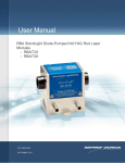
For example, if the chiller is running at 22 °C then look at the curve
labeled 22 °C. Suppose the ambient air near the laser is at 28 °C (82
°F), look where the grid-line for air temperature of 28 °C intersects
the curve for diode temperature of 22 °C. At a relative humidity of
70% or greater, condensation will form on the laser diodes.
16
Figure 15 Constant Dew Point Lines for Ambient Temperature and
Relative Humidity
17
Figure 16 Table of Air Condensation Temperature at Given Ambient Air
Temperature (C) and Relative Humidity (%)
If required to operate a laser system in conditions near to the
condensation temperature, take precautions to keep the RB module
dry. The module should be operated inside an area that is purged
with gaseous N2 or encased in a sealed enclosure with a desiccant.
18
Chapter 4
Installation and Operation
When NGST CEO sells diode drive electronics with the RE-Series module, we sell our eDrive diode
driver. When NGST CEO sells a closed loop water chiller with the RE-Series module, we provide a
Polyscience chiller (see Chapter 1 for chiller capacities). The following chapter contains step by step
procedures detailing the installation and operation of the RE-Series module with these peripherals.
CAUTION
The module is susceptible to damage due to electro-static discharge (ESD).
Always use proper ESD control devices when handling the module.
RE-Series Laser Module Assembly and Connections
1. Check to make sure the AC power switch located on the rear panel of the
eDrive Laser Diode Controller is in the OFF position.
2. Connect D-sub on the base of the RE-Series to the Laser Drive Output
located on the rear of the eDrive.
3. Connect the lab door interlock switch (or other interlock used) to the
Interlock connector on the rear of the eDrive. If multiple interlocks are
needed, be sure all interlocks are connected in SERIES to this port. If no
remote interlocks are used, short the connection to allow for normal laser
operation.
4. If an external power supply is used, check to make sure the AC power
switch located on the front of the external power supply is in the OFF (O)
position. Then, connect the output of the supply to the input power lugs of the
eDrive located at the upper left of the rear panel.
5. Verify the eDrive has clear space in rear and on each side of unit to allow
proper air flow.
6. Plug the eDrive and external power supply (if used) cords into the
appropriate facility power. The eDrive diode driver is equipped with universal
power circuitry accepting voltages ranging from 100-260 VAC and a frequency
range of 47-63 Hz.
Figure 17 eDrive Rear Panel
19
Figure 18 System Connections
Figure 19 Chiller Assembly Drawing
20
Closed Loop Water Chiller Assembly
1. Place the chiller on the floor near the RE-Series laser module. Refer to the
chiller instruction manual for power requirements, settings and instructions on
how to set up the chiller.
2. Attach the cooling lines (included with the plumbing accessory kit) to the
hose barb fittings on the chiller and on the RE-Series laser module. Remember
to attach the water filter between the chiller and the laser head. The filter may
be attached to the back of the chiller or to some other stable mounting point
(i.e. wall).
The standard plumbing arrangement for a typical closed loop chiller (including
hose diameters) is shown in Figure 19. The input/output water connections on
the RE-Series are not polarized. Either hose barb on the RE-Series laser
module can be arbitrarily chosen as the coolant inlet. Water flow direction is
not important, as long as the water passes through the filter before entering the
RE-Series laser module.
CAUTION
Do not use de-ionized (DI) water in the closed loop chiller based system. If
you must use DI water, monitor the resistivity (less than 1.0 MΩ) closely and
avoid iron or aluminum parts in the coolant loop.
3. Fill the chiller reservoir and filter housing manually with Purelase 180
coolant (part number 460-Purelase180). Purelase 180 is made from DI water
with additives to control the PH. By using Purelase 180, scale will not form in
the cooling loop. Purelase 180 contains biocide to prevent algae growth and
corrosion inhibitors to protect yellow metals and aluminum.
CAUTION
Do not allow chiller to fill the filter housing, as air can become trapped within
the system.
4. Turn ON the chiller
5. Make sure no air remains trapped in the lines resulting in a positive back
pressure when chiller is turned off. Positive back pressure can hold the flow
switch closed even though flow is not being supplied to the laser module. Air is
trapped in the lines if water level drops when chiller is turned on and then rises
when turned off. Failure to heed this warning may result in the destruction or
serious damage to the device, and will void the product warranty.
6. Verify the pressure gauge located on the front panel of the chiller reads
approximately 50 psi. If it does not, adjust the bypass valve on the rear of the
chiller. Minimum water flow is one gallon per minute. See final test report for
optimum flow rate, which should be ~2 gallons per minute.
21
7. Verify the temperature located on the front panel of the chiller reads
appropriately. Optimum temperature is listed on the final test report but will be
between 20-35 °C.
CAUTION
Do not allow chiller to fill the filter housing, as air can become trapped within
the system.
8. Connect water flow switch to coolant interlock on rear of eDrive diode
driver. When connecting the water flow switch, make sure that it is connected
to the return line of the chiller and the arrow located on the top of the switch
is pointing in the direction of water flow.
Starting the Laser System
Pre-start Conditions
1. Wear laser safety goggles which protect user from1064 nm (fundamental)
and 808 nm radiation.
2. Position the RE-Series module in a laser cavity such the output will be
directed toward a safe target.
3. Verify that the system is correctly assembled.
4. Verify that the rod faces are clean and not capped or covered.
5. Verify that the filter on the closed loop chiller is connected to the inlet hose
barb.
6. Switch the Closed Loop Chiller to the ON position. Verify water flow from
chiller.
CAUTION
Do not operate coolant system below air condensation temperature (dew
point) at laser head. Condensation on the diode arrays can seriously damage
the laser head and may void warranty. Consult a CEO field service engineer if
you have any questions.
Turning On The Laser System
1. Switch the Closed Loop Chiller to the ON position. Verify water flow from
chiller.
2. Verify coolant temperature and flow rate are correct.
3. Turn power switch on external power supply to ON position.
4. Turn the AC power switch on rear of the eDrive to the ON position.
5. Turn the Key switch to the ON position.
6. Before applying current to diodes, shut off chiller to verify that the Coolant
Fault interlock comes on.
7. Restart the chiller. Press clear and verify the error display is no longer
present.
22
WARNING
The output beam and fluorescence of the RE-Series module is a safety
hazard. Avoid direct viewing of the beam or its specular reflection.
Powering the RE-Series Module
1. Form main menu, select Channel Setup Channel 1 Set Current Limit.
Use the selection knob to set your maximum current amplitude to a value
considered safe for the intended module. The eDrive will not allow the current
amplitude to be set higher than the limit. RE-Series modules should never be
run with more than 32 Amps, however to prevent premature diode
degradation, you may wish to set this limit at the beginning of module life to 5
Amps greater than the recommended operating current.
2. From the main menu, select Channel Setup Channel 1 Set Current. Use
the selector knob to select a low current level of approximately 10A.
3. Press EMISSION. After a few warning beeps (approximately 4 second
delay), the eDrive begins to drive the array.
4. Slowly begin to adjust the current amplitude setting until the desired current
level is achieved. Rate f increase in current should not exceed 3A/s. (For initial
operation, see final test report for current.)
5. Using an infra-red viewer or phosphor card continue increasing the current
checking for output at the laser threshold current indicated on the final test
report.
6. Continue increasing the current until the desired output is obtained or until
the current reaches approximately 5 A greater than the current used that last
time an acceptable laser output was achieved. (For beginning of life operation,
see final test report for current.)
7. If you cannot achieve desired output within 5 A, contact CEO for assistance.
Standby Condition
If you are finished using the module but want to use it again within the next
hour, it is best to go to “standby”. To go to standby from a lasing condition,
press the EMISSION button on the eDrive Laser Controller. In this condition,
the drive current to the laser diode shuts off but the closed loop chiller
maintains the optimum diode temperature.
To resume lasing, press the EMISSION button on the eDrive laser controller.
Again an audible warning will sound for approximately 4 seconds prior to
firing the laser.
23
Turning Off the System
1. Press the EMISSION button to turn off drive current.
2. Close shutter (if installed).
3. Switch the main AC power switch on the external power supply, located on
the front panel, to the OFF position.
4. Press the main AC power switch of the eDrive, located on the front panel.
Hold down for approximately 5 seconds until the eDrive shuts down.
5. Allow chiller to run for a couple of minutes (1-2 minutes).
6. Switch the closed loop chiller to the OFF position.
7. Turn off the key switch.
8. Remove the key. Do not leave the laser accessible to people who are
untrained in laser safety or operation.
WARNING
Hazardous voltages are present in this system during normal operation.
Before removing the cover, always disconnect the power cord to the power
supplies and drivers. Allow at least five (5) minutes for all electronics to
discharge before touching or grounding of electrical connections.
24
Chapter 5
Maintenance
Rod Cleaning
CAUTION
Ensure gloves or finger cots are worn during this procedure and that it is
carried out in a clean environment, preferably under a laminar flow hood.
First, blow optical surface with dry nitrogen. Then, use either hemostats and
lens tissue or a tight-wrapped cotton tipped applicator, lightly wetted with
acetone or methanol to wipe the rod face. The wipe pattern should be in a
circular motion from center towards edge. Inspect the rod for cleanliness.
Repeat if necessary.
Adjusting the Operating Current
The specification for laser module optical output is provided in the final test
report delivered with the system. During its early lifetime, the laser diodes will
deliver this specified power at or below 25 A of current. Due to the high
average powers of the diode bars used in your NGST Cutting Edge Optronics
laser module, it is reasonable to expect the diode array to gradually degrade
with use.
Determining when the current limit requires adjustment:
Make sure the temperature is at the correct set point. If the temperature is
incorrect low output power can result, leading to unnecessary current increases.
Check to make sure the rod faces are clean. If the rod faces are dirty low
output power will result, leading to unnecessary current increases. Check to
make sure the coolant and filter are clean. If the coolant is dirty, deposits
accumulate on the Nd:YAG rod, which prevents absorption of diode light.
This results in low output power, leading to unnecessary current increases. If
the temperature is correct and the rod faces and coolant are clean, yet the
output power is still low, the operating current may need to be slightly raised.
Contact your NGST Cutting Edge Optronics field service engineer if you have
any doubts.
CAUTION
Raising the current limit before it becomes necessary can severely shorten
diode lifetime.
Adjusting the Temperature Set Point for the Re-circulating Water
Chiller: The temperature set point for the water chiller was determined at
NGST CEO and indicated on the Final Test Report. Normally the temperature
will not need adjustment. It is possible however, that this adjustment may be
recommended by your Cutting Edge Optronics field service engineer during
the later part of the laser diodes’ lifetime and after several current increases.
25
Increasing the diode drive current increases the heat load on the diode,
resulting in a shift in diode wavelength. In order to compensate for this shift a
slight adjustment, most likely colder, of the temperature set point on the
recirculation water chiller may be required. Changing the temperature set point
will change the output wavelength of the laser diode; this adjustment should be
done in one degree Celsius increments. Look for an increase in optical output
power on an external power meter. Wait a few minutes between each
adjustment allowing the chiller to stabilize. Continue until you obtain the
maximum possible power.
CAUTION
Do not operate coolant system below air condensation temperature (dew
point) at laser head. Condensation on the diode arrays can seriously damage
the laser head.
Cleaning the Chiller
Every six months, the chiller should be drained and cleaned. The filter should
be replaced, and new clean coolant should be used in the chiller. The
recommended procedure for cleaning a chiller is detailed below.
1. Drain chiller completely.
2. Remove filter from housing.
3. Add the 460-CCL2567 cleaning solution to the cooling system till full.
4. Circulate the cleaner for a minimum of 30 minutes.
5. Drain system completely.
6. Refill system with cleanest water available (preferably distilled,
demineralized, or reverse-osmosis)
7. Circulate rinse water for 20 minutes.
8. Drain system completely.
9. Refill system with cleanest water available (preferably distilled,
demineralized, or reverse-osmosis)
10. Circulate second rinse water for 10 minutes.
11. Drain system completely.
12. Install new 5 micron filter into housing.
13. Record cleaning date on sticker with a six-month reminder to drain & clean
the system. Affix sticker to chiller (or cabinet).
14. Refill chiller coolant reservoir with Purelase 180 coolant.
15. Chiller ready to use.
26
Chapter 6
Service
The only user serviceable part in the RE-Series module is the Nd:YAG rod, which can be replaced by the
user. YAG rods rarely break, frequent replacement may be a sign of another problem in the RE-Series
module. Contact Cutting Edge Optronics if you have any further questions.
Rod Cleaning
CAUTION
Ensure gloves or finger cots are worn during this procedure and that it is
carried out in a clean environment, preferably under a laminar flow hood.
1. Remove four fasteners releasing Macor shields.
2. Using hemostats and lens tissue, wetted with acetone or methanol, wipe the
rod face in a circular motion from the center of the rod to the edges.
3. Inspect the rod for cleanliness.
4. Reinstall Macor shields. Ensure that the gap is minimal between Macor
shield and laser rod. The Macor shields protect the retainer nut and O-rings
from stray laser radiation.
Rod Removal and Replacement
CAUTION
The module is susceptible to damage due to electro-static discharge (ESD).
Always use proper ESD control devices when handling the module.
CAUTION
Ensure gloves or finger cots are worn during this procedure and that it is
carried out in a clean environment, preferably under a laminar flow hood.
1. Remove four fasteners releasing Macor shields.
2. Remove the two retainer nuts from the ends of the module using the CEO
spanner wrench#60-590-1.
CAUTION
Use extreme caution during the remaining steps of this procedure to insure
that the rod faces and/or coatings are not damaged. Never use a tool that can
scratch the rod on the O-rings.
3. Extract one of the O-rings that hold the rod in place using a dental pick or
other similar tool. Stick the sharp end of the dental pick into the O-ring and
pull away from the pump module. New O-rings will be used during the
installation of the new rod. Be very careful not to damage the rod ends, or
barrel, with the extraction tool.
4. Remove the rod by applying slight pressure in order to break the O-ring seal
on the opposite end. Partial extraction of the O-ring on the opposite end may
27
be needed. If necessary, loosen the O-ring with the dental pick. Once again,
be careful not to damage the rod ends, or barrel.
Figure 20 Rod Replacement Drawing
5. Clean threads on endcaps and retainer nuts with a Q-tip . This should
ensure that the parts are free of debris.
6. Unwrap the new rod and inspect the end faces.
7. Obtain two #010 white Viton O-rings when using a 6.35mm diameter rod.
8. Place one of the corresponding O-rings over one end of the rod. Position
the O-ring approximately 10mm from the end of the rod.
9. Insert the opposite end of the rod into the corresponding hole in one end of
the module until it protrudes from the hole in the opposite end. The rod is
very fragile. Be careful not to chip or scratch the rod while inserting it.
10. Inspect the rod end (with o-ring) for cleanliness. If needed, clean the end
of the rod with methanol and cotton swabs.
11. Place one of the retainer nuts over the end of the rod with the O-ring.
Thread the retainer nut in until it is finger-tight.
12. Place the second white O-ring over the opposite end of the rod.
13. Inspect this rod end for cleanliness. If needed, clean the end of the rod
with methanol and cotton swabs
14. Thread the second retainer nut into the pump module.
15. Using the retainer nut, carefully push the o-ring into the groove. Seat Oring into groove.
16. Position the rod equidistant from each end of the pump module using the
soft end of a cotton swab.
28
17. Tighten the retainer nuts with the spanner wrench just enough to compress
the O-rings. Do not over-tighten. Over-tightening may cause unwanted strain,
or possibly damage the rod. Tighten the retainer nuts approximately a quarter
turn past finger-tight.
18. Reinstall Macor shields. Ensure that the gap is minimal between Macor
shield and laser rod. The Macor shields protect the retainer nut and O-rings
from stray laser radiation.
19. Inspect both rod ends for cleanliness. Due to the abrasive nature of
threading two metal parts together metallic dust particles may have found there
way onto the rod ends. If necessary, clean the ends of the rod with a puff of
dry nitrogen or moisture-free canned air.
20. Leak test according to the following procedure. Alternately, turn on the
chiller and allow coolant to flow for approximately 20 minutes. Examine pump
module for leaks.
21. If pumphead leaked: first fix the leak, then test again for leaks, finally allow
module to dry thoroughly before lasing. Firing wet diodes will permanently
damage them.
Leak Test Procedure
Laser diodes are very sensitive to water damage. If you have access to
pressurized nitrogen and a pressure gage, you can test for leaks without
exposing the diodes to water.
Figure 21 Nitrogen Leak Test Layout
1. Attach a nitrogen source to one of the water ports on the module being
tested (test article) and attach the termination valve to the other water port on
the test article.
2. Close the termination valve.
3. Open the inlet valve and adjust the regulator to obtain 80 psi on the pressure
gauge.
4. Close the inlet valve. Wait.
5. Return after 30 minutes and record pressure on the gauge. Subtract this
pressure from starting pressure of 80 psi to get the pressure drop over 30
minutes.
6. Pass/Fail requirements: if the pressure drop is greater than 3 psi FAIL, if the
pressure drop is less than 3 psi PASS.
29
Chapter 7
Return for Repair
At NGST Cutting Edge Optronics, we are proud of the durability of our products. Our manufacturing and
quality control processes emphasize consistency, ruggedness, and high performance; nevertheless, even the
finest instruments break down occasionally. We believe that the reliability record of our instruments
compares favorably with that of our competition, and we hope to demonstrate that we provide superior
service by providing dependable instruments and, if the need arises, service facilities that can restore your
instrument to peak performance without delay.
When calling for service inside the United States, dial 636.916.4900. To phone for service in other countries,
contact your sales agent.
Return of the Instrument for Repair
Contact NGST Cutting Edge Optronics or your local distributor for shipping
instructions, and forward the instrument prepaid to the destination indicated.
WARNING
Failure to obtain proper shipping instructions may result in damage to the
instrument.
Remove all water from module by blowing dry air through it for 20 minutes,
prior to packaging for shipment. Place a shorting connector across the
electrical connector. Place module in a sealed bag inside shipping container.
Place some form of desiccant in bag with module.
Special NGST Cutting Edge Optronics packing boxes designed to securely
hold instruments during shipment should be used. If shipping boxes have been
lost or destroyed, we recommend that you obtain a new one, for a nominal
charge, from NGST CEO.
WARNING
Residual water damage, due to condensation or expansion when tightly sealed,
can catastrophically damage the diode arrays or laser rod. Such damage is
excluded from warranty coverage.
Warranty
NGST CEO sends the applicable warranty to the prospective purchaser with
each quote. Contact NGST CEO Sales and Marketing personnel for additional
copies or to answer any warranty questions.
Disposal
In accordance with WEEE (Directive 2002/96/EC of the European
Parliament and of the Council of 27 January 2003 on waste electrical and
electronic equipment), Cutting Edge Optronics accepts the return of our
products for disposal. Please package the products as directed for a return for
repair. Contact NGST CEO or your local distributor for shipping instructions
and indicate inform them of a return for disposal. Forward the instrument
prepaid to the destination indicated.
ROC ROHS Declaration
In accordance with the Clause 6.2 of Marking for Control of Pollution
Caused by Electronic Information Products (SJ/T11364:2006) for Measures
for the Administration on Pollution Control of Electronic Information
Products No. 39, Order of the Ministry of Information Industry of the
Peoples Republic of China, NGST CEO includes the following information
about our laser modules.
The translation document below is according to clause 6.2 of SJ/T 11364:2006
Figure 22 ROHS Declaration Table
31
Northrop Grumman Space Technology
Cutting Edge Optronics
20 Point West Boulevard
Saint Charles, MO 63301 USA
636.916.4900 phone • 636.916.4994 fax
32