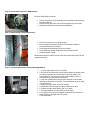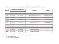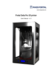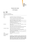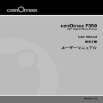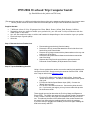
1
1999-2004 Overhead Trip Computer Install
(by Harold Morris aka jetskier on TDS.com)
(This procedure was done on a 2000 truck without the factory wiring at the passenger side kick panel. If you have a newer
vehicle, please consult the service manual for that model year to verify the wire locations and functions)
Supplies Needed:
•
•
•
•
•
7 different colors of 18 or 20 gauge wire: Blue, Black, Green, Yellow, Red, Orange, & White.
Depending how you prefer to attach your ground wire, you will need 2 crimp connectors with the
metal loops on the ends.
You will also need wire taps or solder and heatshrink depending on the connection type you prefer.
Electrical tape of good quality.
Wire ties
Step 1: Remove the Inner Fender Liner
•
•
•
•
•
Disconnecting ground wire(s) from the battery.
Remove the four (4) screws that attach the driver's side front inner
fender lining to the outer fender.
Remove the (4) larger screws with the plate washers on the top, rear
and front (2) of the lining.
Remove the two plastic button fasteners at the bottom toward the
rear of the lining.
Separate the lining from the outer fender to gain access to the
Powertrain Control Module (PCM) located on the firewall.
Step 2: Tap the PCM Wiring Harness
Using a 10-mm socket with a ratchet, remove the retaining bolt attaching the
connector to the PCM. Gently remove the connector from the PCM. Install
wire T-taps on wires in the Reference Table.
•
•
•
Pin 43 (or Pin 9 Gas) is the signal for the fuel flow. Connect the
"Green" wire to this pin. This data is calculated based on the injector
duty cycle.
Pin 58 is the Vehicle Speed Sensor input (VSS). Connect the
"Black" wire to this pin.
Pin 100 is the fuel tank level sensor. Connect the yellow wire this
pin. If you have a gas engine, you may have to make this tap near
the instrument cluster.
These signals are used to determine the Fuel Avg Usage and Distance to
Empty (DTE). The VSS is also required if you want the Outside Temperature
to rise. If there is a fault in this signal, the temperature will drop, but never
rise. This reduces the effect of the radiant heat of the coolers located near
the sensor from influencing the readings while the vehicle is stationary.
If you have a chip or programmer installed, you will have higher readings for
both fuel economy and DTE.
Step 3: Connect the wires to the PCM harness
The three PCM wires connected.
•
•
•
Tape or heat shrink (if you soldered) the connections to protect them
from the elements.
Reconnect the connector to the PCM and tighten the 10-mm bolt.
Reinstall the fender liner and associated hardware..
Step 4: Install Outside Temperature sensor
•
•
•
•
•
Remove left side front turn signal housing.
Mount outside temperature sensor to core support behind the
honeycombed portion of the grill.
Route harness behind battery and up to firewall.
Route PCM and outside temperature wires through firewall.
Reinstall signal housing.
Please note that some vehicle may have the harness already in place for the
temperature sensor.
Step 5: Tap Dash Illumination Circuit at Headlight Switch
•
•
•
•
•
•
•
•
•
1. Turn the light switch to the "on" position.
2. Pull out on the switch knob until it stops and then pull slightly more
to reveal an access hole on the bottom of the knob (about 7:00
o'clock position). This hole may not be totally visible but can be
accessed using a small pocket screwdriver.
3. Push the screwdriver through the hole and push on the release
tab while gently pulling on the knob. The knob should come off easily
- Do Not Force It.
4. Position the light switch to the "off" position.
5. Rotate the knob 180 degrees and put it back on the post.
6. Position the light switch back to the "on" position.
7. The light panel can now be pulled out of the dash.
8. The gauge wire can now be tapped into the blue wire with a red
tracer located on the right side of the panel.
9. Reinstall switch
Step 6: Tap 12V Switched Ignition Circuit
•
•
•
•
Remove the panel under the steering column.
Locate the red wire with the yellow tracer (1999-2001) or light blue w/
pink tracer (2002-2004).
Using a multimeter, verify that it is only hot (12V) when the ignition is
in the "RUN" position only.
Install T-tap and connect to "red" power wire.
Step 7: Tap the Data Link Connector
There are two Light Blue/White wires on the Data Link Connector. The one
located at Pin 16 has 12V from the cigarette lighter. Test to verify - DO NOT
USE this wire.
•
•
Use the wire in DLC Pin 7. It is on the wide face of the connector.
Install the T-tap and connect to the "white" wire.
Step 8: Route the Wires through the Dash
Route all the wires from the PCM, Dash Illumination, DLC, switched power
and the temperature sensor across the dash to the passenger side kick panel
over the glove box
Step 9: Install all wires in the Passenger Kick Panel
Go to your local dealer and ask for some solder leads with the pins. You
may have to talk to the electrical guy in the service department. They will
have them in their bins for harness repair.
•
•
•
•
•
•
Solder and heat shrink each wire and plug the pin in to the
associated slot in the connector. If you cannot get the pins, solder
directly and bypass the connector.
Connect the short "black" wire to the ground screw (green in photo).
Remove the grab handle on the A-pillar and the pillar cover.
Remove the two visors and clips.
Remove the rear view to allow easier access into the headliner.
Route the OEM wiring harness up the A-pillar and snap it into place
into the factory holes. If you have cab lights, you must remove the
existing harness first and use the new one in its place.
Step 10: Cut Headliner for Console Housing
•
•
no picture of cut out
•
•
•
Roughly locate the black console housing in the center of the roof.
Trace the outline and trim the headliner with a utility knife. Be sure
to be conservative around the edges. Remember, check fit and cut
once. The cover will hide a lot of the cut lines. Be especially careful
at the rear of the housing where the tab is on the housing. The
cover-to-housing clearance is tight. If you over trim the headliner,
you will see it here. It is an expensive replacement.
Install the rear tab of the housing into the roof.
Install the harness into the overhead trip computer prior to pushing
the housing into the front pins. There is not enough harness to do it
any other way.
Align the cover over the grooves and push to lock into place.
Step 11: Finalize Installation
Prior to closing up all the panels and trim pieces, this is a good time to check
operation of the OTC.
•
•
•
•
•
Double check all connections.
Reconnect the battery grounds.
Start the engine.
Run through each setting to make sure it is getting a signal. You
should see the temperature sensor reading. The Distance to Empty
should register a number, but it may be inaccurate for you tank size.
Reprogram the tank size with a NGS or WDS scan tool . The
Procedure is here. Print this and take it to your dealer. It should
only take 10-15 minutes max. If you have a 2002 or newer, the
procedure may be slightly different.
Wire Color Reference for Overhead Trip Computer (OTC) Functionality (1999-2004 F-Super Duties)
Connector at Passenger Kick Panel
Wire Color3
Connect to:
Function
Pin 9 (LB/RD)
Light Blue/Red at Main Light Switch
Illumination Feed
Pin 2 (OG/LG)
Pin 10 (OG/LG)
Orange/Light Green at PCM5 (Pin 43)
Injector Duty Cycle Input
(factory with
cab lights)
Pin 3 (BN)
Pin 4 (BN)
no connection to OTC
Cab Light 12V with
parking/headlamps on
(factory with
cab lights)
Pin 4 (BK)
Pin 5 (BK)
no connection to OTC
Cab Light Ground
White
Pin 5 (LB/WH)
Pin 13 (LB/WH)
Data Link Connector2 (Pin 7)
Allow programming tank
size for DTE4
Yellow
Pin 6 (YE/WH)
Pin 14 (YE/WH)
PCM (7.3L Pin 100)1
Fuel Tank level sender
Red
Pin 7 (RD/YE)
Pin 1 (LB/PK)
Ignition switch
12V in Start or Run
Black (short)
Pin 8 (PK/OG)
Pin 2 (PK/OG)
Ground at Kick panel
Vehicle Ground
Orange
Pin 9 (LB/OG)
Pin 3 (LB/OG)
Outside temp sensor at grill
Outside Temperature
Sensor Input
Black
Pin 10 (GY/BK)
Pin 12 (GY/BK)
Grey/Black at PCM (Pin 58)
Vehicle Speed Sensor
Input
C222 (10-pin)
1999-2001
C264 (14-pin)
2002-2004
Blue
Pin 1 (LB/RD)
Green
1.
2.
3.
4.
5.
Some gas engines don't have the YE/WH wire at the PCM. Locate this wire near the instrument cluster).
There are two Light Blue/white tracer wires on the Data Link Connector. Use the wire in DLC Pin 7
The colors shown are just suggestions. Colored wire can be purchased at any auto parts store.
DTE = Distance To Empty
PCM = Powertrain Control Module
Reprogramming the Overhead Trip Computer
When replacing the OEM tank with a larger replacement tank, it may be desirable
to reprogram the overhead console trip computer so that the distance to empty is more
accurate. The following procedure explains how this can be accomplished on any Ford
truck that has the OTC (Overhead Trip Computer).
1. Install the NGS Service Card (green writing) into the NGST (New Generation
Star Tester)
2. Start the vehicle.
3. Plug in the NGST into the diagnostic connector, which is mounted to the bottom
of the dash. The NGST will automatically power up once it is plugged in.
4. Select (press the TRIGGER button) SERVICE BAY FUNCTIONS.
5. Scroll down and then select OTC.
6. Select FUEL TANK SIZE (this is the only option).
7. Select 99-01 F-SERIES S-DUTY.
Note: There are three other options, which all accomplished the same this:
• • 00-01 EXCURSION
• • 99 F250/F350/F4000 (S. AMERICAN)
• • 00 F250/F350/F4000 (S. AMERICAN)
8. Select FUEL TANK SIZE.
9. Scroll down until you see “----.- GALLONS” and then select this option. This
will highlight the “----.-” and allow a custom volume to be entered.
10. Enter the new volume of the tank (in gallons) using the numbered buttons and
press the trigger button. Be sure to include any leading zeroes. For example the
57.0 gallon tank would be entered as “0057.0”
11. Scroll down and select the VEHICLE.
12. Scroll through the different vehicles and then select the desired value.
13. Select DONE using Button #8 from the row of numbers.
14. The display should read:
MODULE CONFIGURATION COMPLETE
PRESS TRIGGER TO CONTINUE
15. The reprogramming of the OTC is complete. At this point you can press the
trigger to continue with other options or shut off the vehicle.
16. On the next startup you should see the MILES TO EMPTY change on the trip
computer because it is now calculating this value based on the fuel tank size.