1
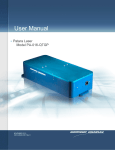
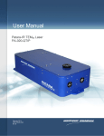
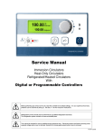
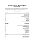
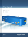
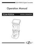
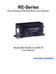
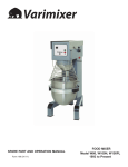
Installation Guide for Patara Laser To ensure safe operation of the Patara laser system, please read the chapters about safety in the laser user manual, eDrive manual, TEC driver manual and chiller manual. It is the purchaser’s responsibility for any loss and injury during installation and use of the laser system. Northrop Grumman Aerospace Systems Cutting Edge Optronics (CEO) recommends that a technician from CEO perform the installation of the laser for the first time. Only qualified technicians should be allowed to perform the installation and maintenance of the laser. If you do plan to service your laser, please use the following procedures. 1. Laser system components Before installation of the laser, it is recommended that you first familiarize yourself with all of the laser components as pictured below. 5) Laser Signal Cable 1) Laser head 2) Chiller 3) eDrive 4) TEC driver 6) Diodes Power Cable 7) QS RF Cable 8) AC Power Cables Figure 1, Components for the Patara laser (except the water hoses and filter). The components for the Patara laser are listed in figure 1. The water hose and filter will be shown below. 2. Unpacking Your CEO Patara laser was carefully packed for shipment. If its carton appears to have been damaged in transit, have the shipper’s agent present when you unpack. Inspect the unit as you unpack it, looking for dents, scratches, or other evidence of damage. If you discover any damage, immediately file a claim against the carrier and notify your CEO representative. CEO will arrange for repair without waiting for settlement of your claim. Keep the shipping container. If you file a damage claim, you may need it to demonstrate that the damage occurred as a result of shipping. If you need to return the unit for service, the specially designed carton assures adequate protection. A Patara laser system consists of: 1) 2) 3) 4) 5) 6) 7) 8) 9) Laser head P/N PA-016-QTGP eDrive P/N ED4C-AXA-2440N TEC driver Laser signal cable Diode power cable Hoses and filter for chiller US power Cord for Chiller US power Cords for eDrive and TEC Controller Chiller. Please check the contents against the packing list and the sales order. 3. Laser head setup Figure 2, Basic setup for the laser power test. The laser head should be mounted on an optical table or equivalent strong flat surface. There are three mounting holes provided to secure the laser. The laser should be installed in a clean environment. In the direction of the laser output beam, place a power meter with the power scale up to 30W approximately 1.5 feet away from the laser. In order to protect the power meter, a negative lens (f=100mm) with AR coating at 532nm should be installed in front of the power meter as shown in figure 2. If a negative lens is not available, the power meter should be at least 2m away from the laser so that the beam size is larger and the power density is below the damage threshold of the power meter. 4. eDrive setup 4.1. Input Power Use only power cords suitable for your driver. Use a power source that is in the range of 90 to 250 VAC-RMS, 47 to 63 Hz. Power switching is done automatically; there are no configuration switches to set for high or low voltage ranging. Observe recommended fuse selection for each voltage range. AC Input Frequency Fuse Ratings (F1, F2) 120V 15A 47-63 Hz 15A 240V 7A 47-63 Hz 8A 4.2. Mounting There are four holes on the front panel of the eDrive designed for the mounting into an EIA-310Dcompliant rack. If the eDrive is to be used on a desktop or table top, it is recommended that the eDrive be equipped with feet to prevent the driver from marring the surface when it is moved. The eDrive must be secured. 4.3. Clearance Adequate clearance should be allowed on the front, sides, and rear of the eDrive for access to connections and components. The front and rear vents of the eDrive must be a minimum of 24 inches (61 cm) away from walls or vertical surfaces so air flow is not restricted. 5. Chiller setup 5.1. Ambient Temperature and Relative Humidity The Chiller is designed for indoor installation in ambient temperatures between 5° and 30°C (41° and 86°F; relative humidity should not exceed 80% (non-condensing). 5.2. Location The Chiller should be installed on a strong, level surface. It should be located as close to possible to the laser. It should not be installed closer than 4 feet (1.4 meters) to a heat generating source, such as heating pipes, boilers, etc. If possible, the Chiller should be located near a suitable drain to prevent flooding in the event of leaks. Do not place it where corrosive fumes, excessive moisture, excessive dust, or high room temperatures are present. For ease of positioning and maneuverability, the Chiller is supplied with casters. The front wheels can be locked to keep the Chiller in place while in use. To help prevent voltage drops, position the Chiller as close as possible to the power distribution panel. Avoid voltage drops by using a properly grounded power outlet wired with 14 gauge or larger diameter wire. The use of an extension cord is not recommended (Note: The Chiller may be located at a level below that of the equipment being cooled. As long as the process remains closed, overflow will not occur when adding cooling fluid to the Chiller reservoir.) 5.3. Clearance Adequate clearance should be allowed on the front, sides, and rear of the Chiller for access to connections and components. The front and rear vents of the Chiller must be a minimum of 24 inches (61 cm) away from walls or vertical surfaces so air flow is not restricted. 5.4. Electrical Power An IEC power cord is provided with the Chiller. It should be attached to the receptacle on the rear of the enclosure. Make sure that the power outlet used for the Chiller is properly grounded and matches the voltage and frequency indicated on the identification label on the back of the Chiller. The use of an extension cord is not recommended. However, if one is necessary, it must be properly grounded and capable of handling the total wattage of the unit. The extension cord must not cause more than a 10% drop in voltage to the Chiller. WARNING DO NOT PLUG THE CHILLER INTO THE ELECTRICAL OUTLET UNTIL THE UNIT IS READY FOR STARTUP. 6. Cables and water hose connection Figure 3, Diagram of water hoses and filter connections Figure 4, Picture of assembled water hoses, filter with the chiller. 6.1. Water hoses and filter connections The water hoses and filters are provided by CEO. They should be connected as illustrated in figure 3. The correct water flow path starts with the SUPPLY port of the chiller->filter-> COOLANT IN port of laser head->laser head->COOLANT OUT port of laser head->RETURN port of the chiller. Please be aware of the flow direction of the filter. Figure 4 is the picture of the chiller with water hoses. Please notice that the positions of SUPPLY and RETURN ports of the chiller are different from the diagram of figure 3. 6.2. Connections on the laser head Figure 5, Connectors on the back panel of the Patara laser. Figure 5 shows all of the connectors on the back panel of the Patara laser. All of the connectors are clearly labeled. The steps for the installation follow. 6.2.1.Plumbing Connection: Push the barb fittings of water hoses connectors gently into the COOLANT IN and COOLANT OUT ports by following the flow patch direction. Wetting the o-rings of the quick disconnect fittings and receptors can prevent the o-ring from being cut by the mating piece during insertion. Make sure that the quick disconnect fittings are locked. A click is heard once it is locked. 6.2.2.Signal Connection: Align the female connector of the laser signal cable to the J1 connector on the laser head. Once it is aligned, the connector can be pushed in. Turn the locking ring of the connector in the clockwise direction until it is locked. 6.2.3.Diode Power Connection: Connect the female connector of the diode power cable to the J2 connector on the laser head. Follow the same procedure of 6.2.2. 6.2.4.RF Connection: Connect the Q-switch RF cable to the BNC connector on the laser head. The connector should be locked as well by turning it clockwise until it stops. 6.3. Connections on the eDrive and TEC controller Figure 6, 7 are the picture of the back panels of eDrive and TEC controller. Figure 6, Picture of the back panel of eDrive. Figure 7, Picture of the back panel of TEC controller. 6.3.1.Signal Connection: Connect the male connector of laser signal cable to the receptacle labeled LASER INTERFACE on the back of eDrive. Follow the same procedure of step 6.2.2. 6.3.2.TEC Connection: Connect the split branch wires of the laser signal cable to TEC controller. Snap the 3 pin connector into the CONTROL connector on the TEC controller. Use a screwdriver to connect TEC power cables (labeled as 1 and 2) as shown below. 6.3.3.Diode Power Connection: Connect the diodes power cable to the receptacle labeled ARRAY POWER by following the same procedure of step 6.2.2. 6.3.4.RF Connection: Connect the QS RF cable to the RF OUT 1 connector as shown below. 6.3.5.Connect the power cords for eDrive and TEC driver. 6.3.6.Make sure everything is connected properly and locked. Check that all of the interlocks (three BNC: “TRIGGER/GATE IN”, “QWS THERM INTLK”, “INTERLOCK”; one black “CHILLER”; and one white “INTERLOCK” shorting connectors) are in place on the back of the eDrive (see figure 6). The black and white connectors are not in place during shipment and will need to be connected by the user. 6.3.7.Layout all of the cables and water hoses and mount the water filter securely. 7. First-time chiller turn-on procedure for PolyScience 6000 Series The first-time turn-on procedure should be similar for use with other chillers. The following steps are for chillers of PolyScience 6000 series. 7.1. Filling the Reservoir Remove the filler cap from the reservoir and, using a funnel, add Purelase 180 until it reaches the MAX line on the reservoir’s fluid level gauge. When full, remove the funnel, but do not replace the cap at this time. 7.2. Electrical Power Plug the Chiller’s power cord into an appropriate electrical outlet. Place the Circuit Breaker/Power Switch on the rear of the instrument enclosure to the “On” position. Three decimal points will appear on the Temperature display; two decimal points will appear on the pressure/flow rate display. 7.3. Starting Process Fluid Flow Press the Power Button on the front panel. The system startup sequence will begin and proceed as follows: The pump will turn on and fluid will begin circulating through the system. The set point temperature will appear briefly on the Temperature display; after a few seconds, it will be replaced by the actual fluid temperature. Fifteen to 20 seconds after power up, the compressor will begin operating. 7.4. Check for leaks ONCE THE PUMP IS TURNED ON, CHECK ALL OF THE CONNECTORS TO SEE IF THERE IS ANY LEAKAGE. IF A LEAK IS OBSERVED, TURN OFF THE PUMP IMMEDIATELY AND FIX THE LEAK. The reservoir’s fluid level will drop as the process and/or process cooling lines fill with fluid. Add fluid as follows: Closed Systems: Slowly add fluid to the reservoir until the liquid level remains stable. Open Bath Systems: Adjust the restriction (pinch) valve until the liquid level in both the bath and the reservoir remain stable. Add fluid as needed to bring liquid levels in the bath and reservoir up to the desired level. Make sure the fluid level in the bath is above the opening on the Chiller’s inlet hose. 7.5. Replace the reservoir cap 8. First time laser turn-on procedure 8.1. Remove the cap that protects laser output window and make sure the window is clean 8.2. Turn on and verify the settings of the chiller 8.2.1.Turn on the chiller. 8.2.2.Check the temperature setting of the chiller. There is a test report attached for each Patara laser. The operational temperature of coolant is written on the report. The temperature setting of the chiller should be the same as in the report. If it is set to a different temperature, change it to match the setting on the report. 8.2.3.The minimum flow rate for Patara laser is 1.5GPM. Check the flow rate to make sure it meets the requirement. If it does not, open the valve inside the chiller until it matches the flow rate recorded in the test report. 8.2.4.Run the chiller for a period of time and wait for the chiller to stabilize at the set temperature. 8.3. Turn on and verify the settings of the TEC controller 8.3.1.Turn on the power with the switch on the back panel of the TEC controller. 8.3.2.By pressing the “DISPLAY SELECT” button; check if the temperature is set correctly according to the test report. The power, pulse width and stability of the laser are strongly dependent on the actual temperature of the TEC driver. If the TEC temperature does not match the test report, change the temperature setting though increase/decrease button. 8.3.3. Wait for several minutes to see if the actual temperature is stabilized at the set temperature. If so, then go to the next step. 8.4. Turn on and check the settings of the eDrive 8.4.1.Flip the power switch on the back panel of the eDrive to the ON or “—“position. 8.4.2.Make sure that the red EMERGENCY button is released. Turn on the eDrive by turning the key to ON position and pressing the POWER button to power up the eDrive. 8.4.3.Check all the laser parameters in the eDrive. Here are the correct settings for the Patara laser Channel: enabled Standby current: 0 A Slew control: Enabled Slew Rate: 5A/sec Current limit: 30A Q switch: enabled QS Frequency: 9 KHz QS window width: 5 µs Q-switch power: 100% FPS: Enabled FPS mode: standard FPS delay: see report Starting power: see report FPS widow length: see report Modulation type: linear PPK open offset: 0 PPK closed offset: 0 Internal trigger: enabled 8.4.4.Make sure that there is no objects in the laser beam path except for the negative lens and power meter. MAKE SURE PROPER LASER SAFETY EYEWEAR IS WORN TO PROTECT YOUR EYES! 8.4.5. Once all the parameters are set correctly, and temperatures of TEC driver and chiller are stabilized, set the current at 10A and press the “EMISSION” button. 8.4.6.Press the “SHUTTER” button to open the laser shutter. Gradually increase the current until the laser is firing at very low power. Move the negative lens and power meter so that the beam is going through the center of the lens and hitting the center of the power meter. 8.4.7.Gradually increase the current set point to the operating current specified in the test report. Don’t touch any part of the laser and wait for the laser to stabilize for 1 hour (usually the laser takes around 20 minutes to reach 95% of the maximum power). Then check if the power is close to the result on the test report. Usually the laser needs optimization for the first installation due to the slight differences of environments, chiller settings and vibration of the transportion. 9. Laser performance optimization At this time, there should be green light coming out of the laser. If not, contact CEO for help. To reach the best performance, the laser may need very slight adjustments to optimize the alignment. Here are the procedures one should follow: 9.1. Wait for the laser to reach thermal stabilization Both the laser bench temperature and environmental temperature significantly impact the laser power. Wait for the laser to be thermally stabilized before attempting any adjustment. 9.2. Check the settings of the eDrive and chiller During installation, it is advised that the performance of the laser be checked according to the factory’s default settings. Check that all of the eDrive settings are correct. The water flow rate and coolant temperature have a significant impact on the laser performance. Make sure that the flow rate is above 1.5GPM and the temperature of the chiller is right according to the test report. 9.3. Peak up the laser power by tuning the temperature of the TEC controller The phase matching of the second harmonic generation (SHG) crystal is crucial for the Patara laser. The phase matching is controlled by setting the proper temperature on the SHG crystal. The temperature is controlled by the TEC controller. Figure 8, Example of dependence of power and pulse-to-pulse instability on the temperature of SHG crystal Figure 8 shows an example of the dependences of the power and pulse-to-pulse instability on the temperature of SHG crystal. As shown in the example, one should choose the middle point of the temperature band, which is around 28.5 oC according the above figure. The laser may have the best power at 29.3 oC in this example, but a small temperature change on the SHG could result in power fluctuation. 9.4. Peak the laser power by tuning the current Figure 9, Example of dependence of laser performance on the pumping current. Figure 9 shows an example of the dependence of the output power and pulse-to-pulse instability of Patara laser. As one can see, the laser power increases as the pumping current is increased. The laser had the peak power around 23A in this case. One should search for the peak power by changing the current in steps of 0.1A around the operating current. Once the peak power is found, one should lower the current to have 99.5% of the peak power. Set it as the operating current. In this example, the operating current would be 22.9A according to figure 9. The slight difference between the actual operating current and the one on the test report may be due to the performance difference of the chillers. An increase of in the pumping current can compensate for the aging of the laser diodes inside the Patara laser. 9.5. Peak up the laser with adjustment of the cavity mirrors Figure 10, Illustration of accessible holes for HR and HM cavity mirror adjustment WARNING MAKING MIRROR ADJUSTMENTS CAN BE NON-REVERSIBLE. IT CAN BE DIFFICULT TO RETURN THE LASER TO THE INITIAL STATE. DO THIS STEP ONLY WHEN THE ALL ABOVE STEPS ARE FINISHED AND LASER DOESN’T MEET THE SPECIFICATIONS WITH THE CORRECT SETTINGS. 9.5.1.Identify the locations of access holes for HR and HM mirrors. Please pay attention to the positions of HR and HM mirrors with respect to the direction of the laser output. 9.5.2.Remove screws from access holes only in a dust free environment. 9.5.3.Use a 1/8” ball driver to make adjustments. A final adjustment is 1° or less rotation. A small adjustment is about 2° of rotation. A coarse adjustment is 15 or 20° of rotation. If coarse adjustments are needed to obtain performance, reduce operating current by 2A. Return to normal operating current when making small and final adjustments. 9.5.4.The screws for the adjustments of the vertical tilt angle and the horizontal tilt angle are illustrated in figure 10 above. 9.5.5.Adjustment procedure for the power optimization 10. Make small adjustments to the horizontal angle of HM mirror and observe the output power. Once a maximum is found, try adjusting the vertical control of HM mirror to maximize power. Make small adjustments to the horizontal angle of HR mirror and observe the output power. Once a maximum is found, try adjusting the vertical control of HR mirror to maximize power. Go back to steps 9.3 and repeat the optimization steps until there are no significant performance improvement. If the laser power cannot be restored to the specification, or the laser is not stable, then the laser the procedure of “Walking the Cavity” can be tried. o ”Walking the cavity” is sometimes required to optimize the laser and involves combining mirror mount and SHG crystal temperature adjustments. o Reduce current by 2A while making coarse adjustments. Return current to normal when making fine adjustments. o Make a horizontal adjustment to the HM mount. Recover the laser power by making a similar adjustment to the horizontal control of the HR mount. Check and adjust the temperature of SHG crystal. o Continue if improvement is noted. If no improvement - try the opposite directions. o Perform the same procedure with the vertical adjustments of the HM and HR mount. o Typically, SHG temperature adjustment is not needed when doing vertical adjustments. Periodically check for hold off when making these adjustments (see the steps in chapter 5 of the user manual to check for hold-off). If the laser reaches within +/-5% of nominal power (typical power meter accuracy), and it has good beam shape and stability, one should stop and replace the access screws in the cover. Laser turn off procedure 10.1. Press SHUTTER to stop the lasing. 10.2. Press EMISSION key on eDrive. Pump light will cease. 10.3. Press POWER key on eDrive and hold for 5 seconds until display turns dark. 10.4. Turn the key of eDrive power switch to OFF. 10.5. Let chiller run for 1-2 minutes. 10.6. Turn off the TEC controller 10.7. Turn off chiller.