1
System Configuration Guide
© 2015 Powerit Solutions
© 2015 Powerit Solutions, LLC. All rights reserved.
This document, as well as the software described in it, is furnished under
license and may be used or copied only in accordance with the terms of
such license.
Products that are referred to in this document may be either trademarks
and/or registered trademarks of the respective owners. The publisher and
the author make no claim to these trademarks.
Powerit Solutions, LLC assumes no responsibility or liability for any errors
or inaccuracies that may appear in this documentation.
Except as permitted by such license, no part of this publication may be
reproduced, stored in a retrieval system, or transmitted, in any form or by
any means, electronic, mechanical, recording, or otherwise, without the
prior written permission of Powerit Solutions, LLC.
Powerit Solutions, LLC
307 3rd Ave South, Suite 400
Seattle, WA 98104
phone: 866-499-3030
fax: 206-340-9201
Contents
3
Table of Contents
1
Introduction
4
2
Set up the Appliance
6
3
Verify Spara Hub
Connection
8
4
Configure Display Settings
10
5
About Modbus Integration
13
6
Connect to Meters
15
6-1 Testing and Verification
7
Connect to Loads
7-1 Testing and Verification
8
9
10
15
19
19
Configure Demand
Management Settings for
Loads
26
Configure Demand
Management Settings for
Account
29
Troubleshooting
31
© 2015 Powerit Solutions
4
1
Spara Go System Configuration Guide
Introduction
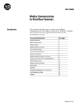
This guide provides detailed procedures for setting up a Spara
GoTM system used to manage your facility's electrical energy
usage. Perform the setup steps by following the sections in this
guide in order.
Definitions
Spara Go application: The software application that collects
meter and load data, controls the Spara Go appliance, manages
the demand, and communicates with the Spara Hub platform or the
Spara View user interface.
Spara Go appliance: The hardware platform that the Spara Go
application runs on. The Advantech ARK 1122 is the current Spara
Go appliance. Note: The Spara Go appliance may be referred to as
the Spara DM appliance in the Spara Hub and Spara View user
documentation.
Spara Hub® : The cloud-based, full-featured interface to the Spara
Go application and appliance.
Spara View ® : The local user interface to the Spara Go application
and appliance.
System Architecture
© 2015 Powerit Solutions
Introduction
5
See Also
The Spara Hub documentation link
(https://
www.sparahub.com/docs/Spara Docs Index.html) provides access
to the following documents:
Spara Go Configuration Reference provides the following
sections:
"Using Simulated Data"
"Setting Pulse Rate"
"Connecting to the Terminal Interface"
"Changing Time Settings"
"Changing Network Communication Settings"
"Terminal Interface Command Reference"
"Modbus Map Subset"
"Spara Go PLC Sample"
Spara Hub User Manual provides information on using the Spara
Hub Demand Manager user interface to the plant.
Spara View for Spara Go User Guide provides information on
using Spara View web user interface to the plant.
Spara Go Modbus Map provides the complete Modbus map for
the Spara Go system.
© 2015 Powerit Solutions
6
2
Spara Go System Configuration Guide
Set up the Appliance
Set up power and internet connection
1. Connect the Spara Go appliance to the provided power supply in
a safe location for operation. Most installations will require a
protective enclosure rated for the environment.
Note: A DIN-rail is installed on the appliance for easy
mounting. You can remove the rail by removing four screws if
you need to install the appliance another way. Optional wallmounting hardware (bracket, screws, allen wrench) is included
with the Spara Go system.
2. Turn on power to the appliance by plugging the power supply
into a 115VAC receptacle and verify the appliance is powered on
by observing the green power on status light.
3. Connect an Ethernet cable between your network (LAN) that has
internet access and Eth Port 0 on the appliance. Note: For
Spara Go to be fully functional it needs to be connected to
Spara Hub via the internet. There are two Ethernet ports on the
appliance, but only Port 0 is configured to connect to Spara
Hub.
© 2015 Powerit Solutions
Set up the Appliance
7
Notes:
The default network configuration setting for Eth Port 0 is DHCP. If
your network is not set up for DHCP, see "Connecting to the
Terminal Interface" in the Spara Go Configuration Reference to
configure a static IP address for Eth Port 0.
Your network must support the following: Secure and encrypted
data and management channel initiated by the Spara appliance to
the Spara Hub user interface via SSL/TLS VPN - Port 1194.
© 2015 Powerit Solutions
8
3
Spara Go System Configuration Guide
Verify Spara Hub Connection
Spara Hub is the primary, cloud-based user interface for the Spara
Go system. In this section you will start the Spara Hub interface
and verify the connections and that the Spara Go system is
registered with Spara Hub.
Connect to Spara Hub
1. In a browser, navigate to www.sparahub.com and log in using
the credentials provided with your Spara Go appliance.
2. You will be prompted to change your password before you use
Spara Hub.
3. Log in using the new password.
© 2015 Powerit Solutions
Verify Spara Hub Connection
9
Confirm the Connection
1. The main page will look similar to the following. Note: Click the
help link
for more information on this feature.
2. Confirm the connection between Spara Hub and the Spara Go
appliance by checking the status indicators. Note: It may take
up to 5 minutes for the connection status to update. The
indicator on the left should be a checkmark
screenshot.
, as shown in the
3. If the status indicator is as shown, the connection between
Spara Hub and the Spara Go appliance is working properly.
Continue with the configuration steps. If the status indicator is
not as shown, the connection is not working properly; see
Troubleshooting.
© 2015 Powerit Solutions
10
4
Spara Go System Configuration Guide
Configure Display Settings
In this section, you can customize some basic settings for your
system:
Change the names of any of the labels to names that are
meaningful at your facility.
Enable and disable Spara Go management for individual loads,
so that the Loads displays are filtered to show only enabled
loads.
Simulation
You can set the system to produce simulated data if you want to
familiarize yourself with the interface before customizing the
display and before completing Modbus integration. To do so, you
must enable simulation mode in the Spara View interface. Spara
View is the interface local to the Spara Go appliance. It is typically
used to provide access to the data and settings when
circumstances (e.g., internet outage) prevent access to the
internet and the Spara Hub interface. It includes the optional
Simulation mode setting.
If you want to look at simulated data, follow the instructions in the
"Using Simulated Data" section in the Spara Go Configuration
Reference. Click the
document.
button in Spara Hub to find a link to the
Note: When you are ready to continue with this section, be sure to
disable simulation mode, and return here.
Node Hierarchy
The data supplied in the Spara Hub interface is organized in a
hierarchy of nodes from the company to the load as follows:
"Enterprise" is the company.
"Facility" is the building, location, branch, etc., where Spara Go
is installed.
"Utility Acct #" is the utility account for the loads that Spara Go
is managing. There can be only one utility account (and one
utility account bill) for each Spara Go appliance. Some facilities
may have multiple utility accounts.
© 2015 Powerit Solutions
Configure Display Settings
11
"Meter #" is the electrical meter for the loads. Spara Go
supports two meters. If the account has more than two meters,
they must be combined in another plant automation system
(e.g., PLC) before communicating with Spara Go.
"Load #" is the equipment that Spara Go is managing. Up to 10
digital and 10 analog loads are supported. E.g., fans, freezers,
heaters, furnaces, etc. Default names for the digital loads are
Load_D1, Load_D2, and so on. Default names for the analog
loads are Load_A1, Load_A2, and so on.
Customize Display
1. Click the Spara Hub Settings icon.
2. Expand the Node Configuration section.
3. To change the name of any node, click in the field and edit the
name. After making your changes, click Accept.
© 2015 Powerit Solutions
12
Spara Go System Configuration Guide
4. To enable or disable a load, and thus filter which loads are
shown in the other Spara Hub displays, click the appropriate
button.
indicates that the load is enabled.
indicates
that the load is disabled. After making your changes, click
Accept.
5. If the time shown in the display is incorrect, after completing
other setup steps, see the Spara Go Configuration Reference for
instructions.
© 2015 Powerit Solutions
Configure Display Settings
5
13
About Modbus Integration
You must have an understanding of the Modbus protocol to perform
Spara Go Modbus integration. If you do not, before proceeding,
please visit www.modbus.org to research the publicly available
documentation.
Spara Go functions as a Modbus/TCP server (e.g., slave). It allows
use of function code 03 to read from and function code 16 to write
to holding registers (4XXXXX). It allows use of function code 04 to
read from input registers (3XXXXX). Writing to input registers is not
allowed.
You must configure Modbus TCP communications with the Spara
Go appliance to provide feedback and control at your facility. See
the Spara Go Modbus Map (provided in the Spara Hub
documentation link
) for reference information for all register
descriptions and address locations. You must also configure your
PLC or other automation communication to interact with the
appropriate Modbus address locations.
Logical Structure
The Spara Go Modbus Map is logically structured into three major
groups as follows:
Utility account control parameters and operating values (Modbus
address range 15001-17000)
Individual utility meter control parameters and operating values
(Modbus address range 17001-20000)
o Spara Go supports input from either one or two utility meters
with similar data and parameter structures for each meter.
o The Modbus Map data structure is similar for each meter with
an address index of 50. (i.e., Meter 1 60 second average
power (kW) is found at address 17011, Meter 2 is found at
address 17061)
Individual load control parameters and operating values (Modbus
address range 1-15000)
o Spara Go supports up to 10 discretely (on/off) controlled loads
with similar data and parameter structures for each load.
© 2015 Powerit Solutions
14
Spara Go System Configuration Guide
o Loads identified as 1-10 correlate to the 10 discretely
controlled loads.
o Spara Go supports up to 10 analog controlled (0-100%) loads
with similar data and parameter structures for each load.
o Loads identified as 11-20 correspond to the 10 analog
controlled loads.
Modular Data Types
Boolean parameters have two values: 0 or 1 (i.e., False or True)
Short parameters are 16-bit integers.
Int parameters occupy two sequential register locations.
The first register contains the low (least significant) word.
The second register contains the high (most significant) word.
Float parameters occupy two sequential register locations and
must be correctly addressed using the IEEE standard.
The first register contains the low (least significant) word.
The second register contains the high (most significant) word.
See Also
On the Spara Hub Documentation page:
"Modbus Map Register Subset" in the Spara Go Configuration
Reference.
"Spara Go PLC" in the Spara Go Configuration Reference for a
sample PLC program for Spara Go systems.
© 2015 Powerit Solutions
About Modbus Integration
6
15
Connect to Meters
In order for Spara Go to be able to accurately control a facility’s
peak demand, Demand Response event participation, and reaction
to Dynamic Pricing, Spara Go must be connected via Modbus/TCP
to a real time kWh feed from the facility’s utility meter(s). This
provides Spara Go the visibility of the overall consumption of the
facility, which is what the facility’s utility bill is based upon. It also
allows Spara Hub to provide overall kWh and kW analytics. Spara
Go provides the capacity to connect up to two separate utility
meters which add up to the overall facility’s utility bill.
Modbus/TCP Integration
Spara Go uses Modbus/TCP to integrate the facility’s utility
meters. This is by done by writing an accumulating pulse count
into the Total Energy holding registers shown below for each
meter. Although two counts per meter are available (i.e.,
integration of a KYZ pulse from a utility meter), only one pulse
count is required. The kWh/pulse scaling multiplier must be written
into the Scaling Multiplier register defined below to ensure that
kWh values are being used by Spara Go and not just counts. If you
want to set this value in the Spara view user interface instead of
through Modbus, see "Setting the Pulse Rate" in the Spara Go
Configuration Reference. If an actual kWh count is being used,
then no change is required, and the Scaling Multiplier can remain
at the default value of 1.
Note: Total Energy count must count up to the full 32-bit integer
value and not roll over beforehand. If it rolls over before counting up
to the full count, an error will occur and some kWh counts will not
be calculated correctly.
Type
Address Type
Holding
17001
Int
Meter 1 Total Energy - kWh
Pulse Count 1
17003
Int
Meter 1 Total Energy - kWh
Counts
Pulse Count 2 (Optional)
17009
Float
Meter 1 Scaling Multiplier
R/W
Holding
R/W
Holding
© 2015 Powerit Solutions
Description
Unit
Counts
kWh/pulse
16
Spara Go System Configuration Guide
R/W
Holding
17051
Int
Meter 2 Total Energy - kWh
Pulse Count 1
17053
Int
Meter 2 Total Energy - kWh
Counts
Pulse Count 2 (Optional)
17059
Float
Meter 2 Scaling Multiplier
R/W
Holding
R/W
Holding
Counts
kWh/pulse
R/W
Examples
There are multiple ways in which a facility can integrate the utility
meter into Spara Go, shown as Examples A, B, and C below.
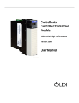
Example A
This configuration shows the connection of a PLC or similar
controller directly to a utility meter’s pulses. This would typically
be directly wired through dry contacts at the meter to a digital input
counter at the controller. These contacts are typically available by
contacting the facility’s local utility and requesting a “KYZ pulse
output” to be installed at the meter(s). During the installation
process, you will also need to acquire the pulse multiplier or pulse
weight (kWh/pulse) from the utility. This value used in the Spara
Go software as described in the "Modbus/TCP Integration" section
above.
© 2015 Powerit Solutions
Connect to Meters
17
Example B
This configuration shows the connection of a PLC or similar
controller to a meter with the capability of communicating over
Ethernet. In this case, a facility may choose to install a “shadow”
or parallel meter(s) with the utility meter. It is recommended that
this meter be a revenue meter to ensure accuracy in relation to the
utility meter that the facility is being billed from. The controller
would then communicate over Ethernet to the meter to acquire
kWh consumption data via any number of various protocols that
the controller may be capable of (Modbus/TCP, Ethernet IP, etc.).
In this scenario, a pulse multiplier is not necessary because the
values should be in actual kWh and not pulse counts.
Example C
This configuration shows the use of a radio transmitter and receiver
to communicate to the meter. This can be an inexpensive solution
for connecting the controller to the meter, considering that the
utility’s meters are often located in inconvenient locations. The
connection at either end of the radios may be a combination of
Option A or B.
6.1
Testing and Verification
Once the meter(s) have been integrated, confirm that meter data is
appearing in Spara Hub:
1. In a browser, navigate to www.sparahub.com and log in.
2. Open the Review - Demand tab. Observe the page and verify
that meter data appears.
© 2015 Powerit Solutions
18
Spara Go System Configuration Guide
© 2015 Powerit Solutions
Connect to Meters
7
19
Connect to Loads
In order for Spara Go to be able to accurately control a facility’s
peak demand, Demand Response event participation, and reaction
to Dynamic Pricing, Spara Go must be connected via Modbus/TCP
to the loads in the facility. Loads may include fans, pumps,
compressors, furnaces, battery chargers, etc.
Modbus/TCP Integration
Spara Go uses Modbus/TCP to integrate the facility's loads. This
is done by reading from / writing to the Modbus registers listed in
the table below. At a minimum, Spara Go requires integration of
Load Status Feedback and Load Reduction Signal for each load.
This gives Spara Go visibility into the energy use of the load as
well as the ability to automatically reduce the energy use.
Spara Go requires load status feedback via the Modbus map,
either by an on/off status for discrete loads or by kW feedback for
analog loads. The Spara Go logic automatically determines how to
use the discrete status or kW feedback.
Spara Go produces a Reduction Signal for each controlled load via
the Modbus map. This signal will be used to coordinate a safe
reduction (i.e., turning down or off) of the load through its existing
controller.
There are also additional features, such as constraint inputs,
which, when compared to a constraint setpoint, will restrict the
reduction of the loads based on process restrictions related to that
load. For example, connecting to an HVAC load, monitoring the
temperature of a room, and writing the current value to the Analog
Constraint.
Type
Addr*
Holding
R/W
© 2015 Powerit Solutions
Type
1 Float
101
Load
Description
D1 Status
Feedback
D2
...
...
901
D10
1001
A1
1101
A2
Notes
Discrete Controlled
Loads: The current
status of the Load.
0=Off, 1=On
Analog Controlled
Loads: The current
pow er
consumption of the
20
Spara Go System Configuration Guide
Holding
R/W
Holding
R/W
Holding
R/W
...
...
1901
A10
6 Float
106
D1 Analog
Constraint
D2
...
...
906
D10
1006
A1
1106
A2
...
...
1906
A10
8 Short
108
D1 Discrete
Constraint
D2
...
...
908
D10
1008
A1
1108
A2
...
...
1908
A10
5 Short
105
D1 Force
Reduction
D2
...
...
905
D10
1005
A1
1105
A2
...
...
1905
A10
load. E.g., 75 kW.
Analog constraint
w ill prevent the
load from entering
or continuing a
reduction w hen
the value is above
or below a
specified setpoint.
E.g., a temperature
setpoint.
The setpoint and
deadband can be
set for each load
on the Spara Hub
Manage - Loads
page.
Discrete constraint
w ill prevent the
load from entering
or continuing a
reduction w hen
the value is high.
E.g., a level
sw itch.
When high, forces
the load to reduce
regardless of
energy
consumption and
setpoint level.
© 2015 Powerit Solutions
Connect to Loads
Input
Read
only
1 Bool
101
D1 Reduction
Signal
D2
...
...
901
D10
1001
A1
1101
A2
...
...
1901
A10
Input
1002 Float
R/W
1102
...
1902
A1 Reduction
Percentage
A2
(%)
...
A10
21
Use this value to
trigger a load
reduction. When
the value is 1, the
load w ill be turned
off or put into a
low pow er
consumption mode.
Analog Controlled
Loads Only:
Use this value in
combination w ith
the Load Reduction
Signal bit. When
Load Reduction
Signal is 1, use this
percentage to set
the level of kW that
the load should be
reduced to.
* For every loads register, Discrete loads (e.g., D1 - D10) use the
first 1000 addresses (e.g., 1-1000); Analog loads (e.g., A1 - A10)
use the second 1000 addresses (e.g., 1001-2000). The addresses
for each load are separated by 100. Thus Load 1 Status Feedback
is address 1; Load 2 Status Feedback is address 101; Load 3
Status Feedback is address 201, etc.
© 2015 Powerit Solutions
22
Spara Go System Configuration Guide
Examples
Example A – Load currently wired/integrated to controller
Load Status Feedback (e.g., starter aux contact – On/Off): Load
status is already present in the controller. Pass this status to
Spara Go via Modbus/TCP.
Load Reduction Signal: Load status is already present in the
controller. Pass this status to Spara Go via Modbus/TCP.
Example B – Load currently wired/integrated to controller
with submeter and constraint
Load Status Feedback (e.g., submeter kW): Load status is
already present in the controller as a kW value. Pass this status to
Spara Go via Modbus/TCP.
Load Reduction Signal: Adapt existing controller logic to use load
reduction signal = 1 to safely reduce or turn off the load (e.g., fan).
Analog Constraint: Pass a monitored value (e.g., temperature) that
is associated with the load (e.g., fan) to Spara Go via Modbus/
TCP. Spara Go will use this to restrict the reduction of the load
based on the current value of that load with respect to a setpoint
configured in Spara.
Example C – Load not currently wired/integrated to
controller
Load Status Feedback (e.g., starter aux contact – On/Off): Wire
status signal directly from load (e.g., motor) to digital input on
controller. Pass this status to Spara Go via Modbus/TCP.
© 2015 Powerit Solutions
Connect to Loads
23
Load Reduction Signal: Wire normally closed contact relay in
series with start/stop circuit for the load starter coil. Turn on relay
based on load reduction signal from Spara Go.
7.1
Testing and Verification
Once the load(s) have been integrated, confirm that the loads can
be managed by Spara Hub:
1. In a browser, navigate to www.sparahub.com and log in.
2. Enable Energy Management.
a. Open the Manage - Demand tab.
b. In the General section, enable Overall Energy
Management, then click Accept.
Note: If you want to disable Spara Hub management and use
the Spara View user interface, which is local to the Spara Go
appliance, you can do so on this tab.
3. Expand the section for the current Time of Use period (e.g.,
Peak). If the Start value for the Demand Control Limit for the
current month is not set to a high enough value to prevent
automatic reductions, set it to a high value and then click
Accept.
© 2015 Powerit Solutions
24
Spara Go System Configuration Guide
4. Verify the Status Feedback signal.
a. Open the Manage - Loads tab.
b. Navigate to the utility account.
c. Expand each load and verify that the status listed ("Running"
or "Off") and its associated kW represent the actual status of
the load.
© 2015 Powerit Solutions
Connect to Loads
25
5. Verify the Reduction Signal value. For each load:
a. Open the Manage - Loads tab.
b. Navigate to the utility account.
c. Make sure that Spara Control is enabled. If it is not, enable it
and then click Accept.
d. Open the Review - Loads tab and observe the power
consumption (kW) values.
e. Set the Modbus Force Reduction signal to 1 for that load
(see Connect to Loads).
f. Verify that the Modbus reduction has occurred in Spara Hub..
g. Look at the value of the load Reduction Signal Modbus
register - the value should be 1.
h. (Analog loads only) Look at the value of the load Reduction
Percentage Modbus register - the value should be 0.
i. Verify that the load has been reduced.
j. IMPORTANT: Set the Modbus Force Reduction signal to 0.
6. Open the Manage - Demand tab. In the General section,
disable Overall Energy Management, then click Accept.
Note: After configuring the load and account settings, you will
re-enable Overall Energy Management.
© 2015 Powerit Solutions
26
8
Spara Go System Configuration Guide
Configure Demand Management
Settings for Loads
Basic and advanced settings are provided for managing the loads.
Advanced features are not discussed in this guide. Click the Spara
Hub help links
or
for more information on all features.
Configure Basic Load Settings
1. In a browser, navigate to www.sparahub.com and log in.
2. Open the Manage - Loads tab.
3. Navigate to the utility account.
4. Expand each load and view the settings.
© 2015 Powerit Solutions
Configure Demand Management Settings for Loads
27
5. For each load, enable or disable control for each Time of Use
(TOU) period.
6. For each load, click
power (kW).
and set the minimum and maximum
Analog loads (controlled by 0-100% reduction signal):
Max. Power is the power which the load is not expected to
exceed.
Min. Power is the minimum power below which the load
cannot be reduced.
Discrete loads (controlled by on/off reduction signal) with
analog power feedback:
Max. Power is the power level when the load is considered
to be ON.
Min. Power is the power level when the load is considered
to be OFF.
© 2015 Powerit Solutions
28
Spara Go System Configuration Guide
7. You can also:
Set time constraints.
Specify the reduction priority.
Specify the minimum and maximum power for the load.
Change analog constraint levels and status. Note: Ensure
that constraint values are being communicated correctly via
Modbus (see Connect to Loads).
Click the help link
for more information on these features.
8. Click Accept to save the settings.
© 2015 Powerit Solutions
Configure Demand Management Settings for Loads
9
29
Configure Demand Management
Settings for Account
A variety of settings are provided for managing all the loads in a
utility account. This section guides you in enabling energy
management and setting basic demand control limits. Advanced
features are not discussed in this guide. Click the Spara Hub help
links
or
for more information on all features.
Configure Settings for the Account
1. If Spara Hub is not open, navigate to www.sparahub.com and log
in.
2. Open the Manage - Demand tab.
3. Navigate to the utility account for your facility.
4. In the General section, the Energy Management and
Demand Limit settings control whether or not the loads in the
utility account are being managed by Spara Go and whether
Spara Hub or Spara View is managing the limits. Verify the
settings, as shown above.
© 2015 Powerit Solutions
30
Spara Go System Configuration Guide
5. Under Demand Control Limit, set the demand management
setpoints.
a. Demand Control: Set starting limits for each Time of Use
(TOU period (e.g., Peak). If you are unsure where to begin,
use these general guidelines:
10% below Peak Demand (kW) on the monthly bill.
– or –
Peak Demand (kW) on the monthly bill minus 25-50% of
total of the loads connected to Spara Go. The % value
depends on the availability of loads for reduction.
b. Demand Response: Set the limit based upon the facility's
specific baseline (calculated by the utility or aggregator)
minus the demand response bid level.
6. For each set of changes, click Accept to save the settings.
7. When you are ready to use the system to manage demand,
enable Overall Energy Management, and click Accept to
save the settings.
© 2015 Powerit Solutions
Configure Demand Management Settings for Account
10
31
Troubleshooting
Status indicator in Spara Hub is not green
The appliance power must be on.
The Ethernet cable must be connected to Eth Port 0.
Your network must be connected to the internet.
Your network must support DHCP or you must have set a static
route. (IP address, default gateway, and DNS server) for the
appliance Eth Port 0. See "Connecting to the Terminal Interface"
and "Changing Network Communication Settings" in the Spara Go
Configuration Reference.
If you set a static route, see if you can successfully ping the
appliance using the IP address that you set.
The time shown in Spara Hub is not right
You can change the time zone and the NTP server. See
"Connecting to the Terminal Interface" and "Changing Time
Settings" in the Spara Go Configuration Reference.
There isn't any power data in the Spara Hub
displays
The utility meter must have a connection to a PLC or similar
controller. That controller must be connected to your
network.
The Modbus/TCP integration for the meters must be
complete. See Connect to Meters.
Modbus is set up for meters and loads, but when I
set Force Reduction high, nothing changes.
Display the Spara Hub Manage/Demand page and verify
that Overall Energy Management is enabled.
Display the Spara Hub Manage/Loads page and verify that
Spara Control is enabled for the loads.
© 2015 Powerit Solutions
32
Spara Go System Configuration Guide
There is data in the displays, but the values don't
look quite right
The utility company pulse rate must be set correctly. Check
the Modbus register; see Connect to Meters.
The NTP server must be set correctly. See "Connecting to
the Terminal Interface" and "Changing Time Settings" in the
Spara Go Configuration Reference.
There aren't any loads displayed on the loads
pages
Display the Node Configuration section on the Spara Hub
Settings page and make sure the individual loads are
enabled.
It doesn't look like the loads are being managed
Display the Spara Hub Manage/Demand page and verify
that Overall Energy Management and Limit Managed by
Spara Hub are both enabled.
Display the Spara Hub Manage/Loads page and verify that
Spara Control is enabled for the loads.
Display the Spara Hub Manage/Loads page and click the
load settings button
power settings.
. Check the maximum and minimum
I don't know what a Spara Hub display is showing
me
Click the "Help on this page"
page.
link for information on the
I need help!
Your Spara Go system includes a defined amount of
technical support. Please submit a support request at:
http://www.poweritsolutions.com/service/service_request/
© 2015 Powerit Solutions
Troubleshooting
© 2015 Powerit Solutions
33