1
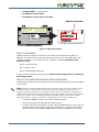
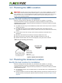
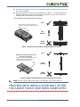
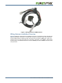
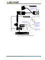
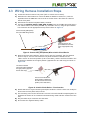
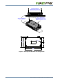
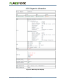
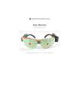
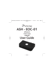
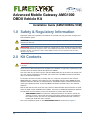
Advanced Mobile Gateway AMG1000 OBDII Vehicle Kit Installation Guide (AMG1000BOx-VCM) 1.0 Safety & Regulatory Information Important safety and regulatory information on the AMG unit may be found on page 14 of this installation guide. CAUTION: Be sure to thoroughly review the safety and regulatory information before installing and activating the AMG unit. WARNING! This kit should only be installed in vehicles 2008 or newer. DO NOT attempt installation in vehicles manufactured in and prior to 2007. A non-OBDII wiring harness unit can be installed on 2007 and older vehicles; connections to older model OBDII interfaces are not supported and can cause damage to the vehicle. 2.0 Kit Contents WARNING! If the vehicle is 2007 or older, this kit should be returned and an “L” kit should be used in its place. There are four AMG aftermarket kits available for installation in light duty or passenger-type vehicles whose on-board vehicle data protocol is OBDII. Two of the kits do not connect to the vehicle’s OBDII data port at all and so can be put into any such vehicle regardless of its model year. These two non-OBDII connection kits differ only in the antenna selection. In contrast, the other two kits, including this one, require a connection to the vehicle’s OBDII data port. However, this product is only compatible with the newer OBDII physical interface called the CAN bus. In North America, compatible vehicles include all those from model year 2008 and newer. These two OBDII connection kits differ only in the antenna selection. Note as well that for each of the four kits, there are both Canadian and US variants. In total, there are eight unique installation kit numbers. There are no installation differences between the Canadian and US variants, so this one document is used to describe both. • AMG1000BOx-VCM kits include the “Backpack Antenna” and will be used in the majority of cases, where both the base unit and the antenna are to be installed in the vehicle interior. This kit is for the OBDII CAN-based interface that is found in model year 2008 and newer vehicles. This is the installation guide for the AMG1000BOx-VCM kit as shown in Figure 1. AMG1000BOx-VCM OBDII Vehicle Kit Installation Guide r01 1 AMG1000BOx-VCM kit contents: AMG1020 x AMG1021B AMG1022OBD2 AMG1022OBDY Advanced Mobile Gateway Backpack Antenna OBDII to AMG Cable OBD-Y Cable (Optional) where: x=U if equipment is to be operated in the USA x=C if equipment is to be operated in Canada Figure 1: AMG1000BOx-VCM OBDII Vehicle Kit For reference, the other three installation kit documents are available at: http://www.fleetlynx.net/mnl The other 3 installation kit numbers are as follows: 2 • AMG1000AOx-VCM kits include the “External Antenna” and should be used when it is necessary to install the antenna on the cab exterior or if specifically requested by the customer. These kits require a connection to the OBDII data port found in model year 2008 and newer vehicles. • AMG1000ALx-VCM kits include the “External Antenna” and should be used when it is necessary to install the antenna on the vehicle exterior or if specifically requested by the customer. These kits do not connect to the vehicle data port. • AMG1000BLx-VCM kits include the “Backpack Antenna” and will be used in the majority of cases, where both the base unit and the antenna are to be installed in the vehicle interior. These kits do not connect to the vehicle data port. AMG1000BOx-VCM OBDII Vehicle Kit Installation Guide 3.0 Pre-Installation Steps IMPORTANT – PLEASE COMPLETE THE FOLLOWING TASKS BEFORE INSTALLATION Turn the vehicle on and check for existing lamps, warning lights, or anything out of the ordinary: Investigate issues as needed before beginning the install - this thorough pre-install exam helps troubleshoot issues should any arise after installation. Please record any lamps or warnings on the installation form. Follow and ensure the completion of all steps in the FleetLynx Installation and Activation Form as well as the AMG1000 Quick-Start Guide. 3.1 Recommended Tools The following tools are recommended for the installation: • Phillips and Square Drive screwdrivers – to unscrew the dashboard • Carpenter knife – optional • Crimp Tool – to attach add-a-circuit fuse accessory • Zipties – to secure loose wiring and perhaps the AMG itself 3.2 Activation Before Vehicle Installation: Step 1: Preparation Please download and review the Installation and Activation Form as well as the Quick-Start Guide. They are found at http://www.fleetlynx.net/mnl Step 2: Collect information Collect the following information for each FleetLynx unit and fill out these fields in your Installation and Activation Form. • AMG Serial Number – see Figure 2 for location of this information • Fleet Name – the name of the fleet the vehicle belongs to • Vehicle Number – the number the fleet uses to identify the vehicle • Dealer Code – the code for the dealership where the FleetLynx unit was purchased from • VIN – the Vehicle Identification Number for the vehicle in which the AMG unit will be installed • Odometer – the vehicle odometer reading from the dash AMG1000BOx-VCM OBDII Vehicle Kit Installation Guide 3 • Company Name – vehicle owner • Installation Contact Name • Installation Contact Phone and email AMG Serial Number Please call to activate (877) 955-3122 It is important that the UNIT S/N is associated with the Truck # that will receive this unit. Veuillez appeler pour activer Il est important que le numéro de série de cet appareil soit associé au numéro du camion qui recevra cet appareil. 5.)43. 5.)43. 1234567890 AMG1020U 1234567890 AMG1020U 0. !-'5 0. !-'5 MODEL: AMG1020U FCC ID: OPP-AMG1020X IC ID: 2943A-AMG1020 AMG Bar Code Label (Close Up) Bottom of AMG Unit Figure 2: AMG Serial Number Step 3: Activation Contact FleetLynx support to activate your unit once the information from Step 2 is obtained. A customer service agent will then activate the unit. It will usually take a few minutes to complete. You may also send us a partially completed Installation and Activation Form. Phone: 1-877-955-3122 Fax: 1-306-657-3177 Email: [email protected] If you are a new customer, please provide the New Customer Application and FleetLynx Service Agreement. Step 4: Pre-Install Verification (Recommended) Preactivate and verify that your FleetLynx unit is operating properly prior to final installation in the vehicle. Note: Installer can use the OBDII interface from the vehicle to power up the unit. All other vehicle connections are not necessary at this point, however this step could take a number of hours to complete. The AMG unit will need to be outside in order to confirm the GPS status and possibly the mobile coverage, depending on the type of building in which the installed unit may be working.However, unless there is ignition or vehicle data being observed, the AMG will shut off after an hour. With a quick-plug connection, it may be necessary to unplug/replug hourly until CELL flashes green. 4 • Connect the OBDII harness to the vehicle’s OBDII connector • Verify that the GPS and PWR LEDs are flashing green • The CELL LED will be solid amber until the unit has established a connection with the cellular provider. This may take a few hours following your request for activation. The CELL LED must be flashing GREEN before the unit is installed in your vehicle. AMG1000BOx-VCM OBDII Vehicle Kit Installation Guide 3.3 Planning the AMG Location WARNING! The AMG unit should be installed and secured in a dry location. Installation in a location where it may be easily accessed by water and other liquids (ie. directly under windshied seams, AC lines, cupholders, etc.) is not recommended. If the AMG is exposed to any amount of any sort of liquid, internal corrosion will occur and the AMG will eventually cease to operate. Damage due to liquid intrusion is not covered by warranty. Identify the best location for installation: Before the wiring harness, AMG base unit and antenna are installed, it is strongly recommended that the vehicle is inspected for potential installation locations and an installation plan is devised. Keep the following information in mind when locating a suitable install location and plan: 1) The AMG base unit may not be installed any further than 9 feet away from the vehicle’s interior fuse panel. 2) The AMG base unit may not be installed any further than 9 feet away from the manufacturer’s OBDII connector which is usually found under the dash near the steering column. 3) Is not visible to the driver during normal vehicle operation to eliminate driver distraction. 4) Will allow the technician to be able to see all four LEDs on the unit. 5) Allows easy access to the GPS, CDMA, and GSM connections on the unit. 6) Enables the AMG base unit to be secured properly using the chosen method. AMG base unit mounting (cab interior): ".(#"4&6/*5 03*&/5"5*0/ $3*5*$"- The mounting location should provide access to the cable connections on the AMG base unit. The mounting location should allow the status LEDs to be visible to the installer. Figure 3: Optimal Unit Orientation 3.4 Planning the Antenna Location Identify the best location for installation: Before the wiring harness, AMG base unit, and antenna are installed, it is strongly recommended that the vehicle is inspected for potential installation locations and an installation plan is devised. Keep the following information in mind when locating a suitable install location and plan: 1) The backpack antenna may be installed either on the AMG base unit or independently up to 3 feet away. 2) Antenna reception is critical for effective AMG operation, therefore the antenna must not be obstructed by metal objects. Optimal antenna orientation is shown in Figure 4 and Figure 5. AMG1000BOx-VCM OBDII Vehicle Kit Installation Guide 5 3) Has clear line of sight to the sky for the backpack antenna, ideally as close to the front of the cab as possible. 4) Allows the backpack antenna to mount parallel to the ground – the ideal placement is horizontal without any metal objects between it and the sky. Unscrew the antenna if needed to place the antenna in an ideal place. Unit mounted with backpack attached to base: #&45 Ideally, this side should be facing UP with no metal objects between it and the sky /05 "%7*4&% "70*% &/5*3&-: Figure 4: Optimal Unit Orientation (antenna attached to base) #&45 Backpack antenna and base unit mounted separately: Ideally, this side of the backpack antenna should be facing UP with no metal objects between it and the sky /05 "%7*4&% "70*% &/5*3&-: Figure 5: Optimal Unit Orientation (antenna separated from base) Note: Record the Pre-Installation Information on the Installation Form located in AMG Kit. PROCEED WITH INSTALLATION ONLY AFTER THE ABOVE TASKS HAVE BEEN COMPLETED 6 AMG1000BOx-VCM OBDII Vehicle Kit Installation Guide 4.0 Connecting the AMG 4.1 AMG Base Unit Connections The AMG base unit connectors are shown in Figure 6. Note: There are two cellular antenna connections, one is for GSM and the other is for CDMA. Be sure to check connections made to the AMG unit thoroughly. GSM Cellular Antenna Connector Main Connector GPS CDMA Antenna Cellular Antenna Connector Connector Figure 6: AMG Base Unit Connectors 4.2 Wiring Harness for OBDII-based Vehicles which are Model Year 2008 and newer The wiring harness for OBDII vehicles is shown in Figure 7. It is one assembly that connects the AMG to the vehicle’s OBDII port provided by the vehicle manufacturer. It also provides a lead wire that needs to be routed to a vehicle electrical source that is powered when the vehicle ignition is on and unpowered when the vehicle ignition is off. This vehicle ignition sensing connection is usually made at the fuse box using the supplied add-a-circuit device. AMG1000BOx-VCM OBDII Vehicle Kit Installation Guide 7 Figure 7: Wiring Harness for OBDII Vehicles Wiring Harness Installation Overview Figure 8 shows the wiring harness installation overview. The following section provides the detailed installation instructions. The general concept is to plug the 8-pin molex connector into the AMG and the D-shaped 16-pin connector into the vehicle’s OBDII port. Lastly, the ignition sense wire gets connected to the fuse panel. Optionally, if the OBDII Y-Cable option is being used, it is installed between the vehicle’s OBDII port and the OBDII connector of the wiring harness. 8 AMG1000BOx-VCM OBDII Vehicle Kit Installation Guide AMG1022OBDY Y-Splitter Cable This cable is OPTIONAL. AMG1022OBD2 can also be connected directly to the vehicle’s dashboard OBDII connector Vehicle Dashboard OBDII Connector AMG1022OBD2 6%()#,%&53%0!.%, OBDII to AMG Cable Add-a-Circuit (JHFUSE-14) Attach GND wire to a good chassis ground point inside the vehicle. These can usually be found near the fuse panel and/or stereo. GND (Black) IGN_SEN (Brown) DIG_IN1 (Violet) OWDAT (Blue) Molex MiniFit Connector Plugs into AMG base unit 5 6 7 8 1 2 3 4 Pinout: 1 = GND1 2 = IGN_SEN 3 = DIG_IN1 4 = GND2 5 = OWDAT 6 = CAN_L 7 = CAN_H 8 = VBATT Connect the Ignition Sensor wire to a spare fuse position which has a “switched” 12V (only live with ignition and accessory) via an “add-a-circuit” device or by direct splice, including a 3A inline fuse, if there is not enough clearance for the “add-a-circuit” device. These wires on the harness are not used. The ends can be taped together and tucked out of the way. AMG base unit (Connector Side) Figure 8: Wiring Harness Installation Overview AMG1000BOx-VCM OBDII Vehicle Kit Installation Guide 9 4.3 Wiring Harness Installation Steps 1) Locate the vehicle’s interior fuse panel (refer to vehicle user manual). 2) Determine the best location to mount the AMG as detailed in Section 3.0, with the stipulation that the AMG base unit must be no further than 9 feet from the vehicle’s interior fuse panel. 3) Disconnect the vehicle’s negative battery terminal. 4) Connect the Ignition Sensor (IGN_SEN - brown) wire on the AMG wiring harness to the “add-a-circuit” fuse holder (JHFUSE-14) included in the kit, using the pre-installed butt connector and an appropriate crimp tool as shown in Figure 9. Connect the IGN_SEN (brown) wire on the AMG wiring harness Crimp the wire into the pre-installed butt connector using an appropriate crimp tool Figure 9: Connect IGN_SEN (Brown) Wire to Add-a-Circuit Device 5) Remove the fuse and install the “add-a-circuit” into the “switched” 12V fuse position found in step 4. The fuse removed from the panel should be installed into the “add-a-circuit” in the lower position (10A or less ONLY), and the 3A fuse included in the kit should be installed in the upper position (opposite the wire and crimp) as shown in Figure 10. The 3A fuse included in the kit should be installed in the upper position (opposite the wire and crimp) The fuse removed from the panel should be installed into the “add-a-circuit” in the lower position (10A or less ONLY) Figure 10: 4 Add-a-Circuit Device – Fuse Insertion 6) Attach GND wire to a good chassis ground point inside the vehicle. These can usually be found near the fuse panel and/or stereo. 7) The remaining wires on the harness are not used. The ends should be taped together to eliminate the chance of an unwanted connection being made and then tucked out of the way. 8) Plug the Molex 8-pin connector into the AMG. 9) Re-connect the negative battery cable. 10 AMG1000BOx-VCM OBDII Vehicle Kit Installation Guide 4.4 Optional Y-cable Installation The optional Y-cable is intended to provide a convert connection to the vehicle’s OBDII port. As well, it keeps the AMG’s cable attachment away from the driver’s legs and thus the connection becomes more reliable under normal vehicle operations. The Y-cable is ordered separately. 1) 2) 3) 4) If necessary, open the vehicle dashboard panel to gain access to dashboard wiring. Remove the vehicle’s current OBDII connector port from the panel bulkhead. Connect the male connector of the Y-splitter cable to the vehicle OBDII connector. Insert one of the female ends of the Y-splitter cable back into the panel location from where the vehicle’s original OBDII connector was removed. It does not matter which of the two female connector ends is used. The optional mounting bracket included with the Y-splitter cable can be used for an alternate mounting point. 5) The remaining free end of the Y-splitter cable is to be connected to the OBDII connector of the main wiring harness as shown in Figure 8. 6) Use cable restraining ties or other technique to secure the cables in a safe and recessed location. 5.0 Mounting the Unit Once the AMG is connected to the Molex 8-pin connector as well as the OBDII connector, the AMG base unit may be secured to the vehicle. An AMG is properly secured when: • It cannot be easily moved or jostled around • The backpack antenna remains horizontal, with a clear line-of-sight to the sky. The backpack antenna needs to be secured also if it has been unscrewed from the AMG. • The 4 lights on the AMG are visible to the installer so that proper operation of the AMG may be confirmed. • No wires are loose or unsecured. Securing the unit using Screws (preferred) The unit may be secured to the vehicle using two #8 Pan Head Screws with a maximum head diameter of 0.325". The recommended maximum torque is 6.0 in-lbs. If holes are to be pre-drilled, space them 6 inches apart as shown in Figure 11. AMG1000BOx-VCM OBDII Vehicle Kit Installation Guide 11 #8 Pan Head Screw Head diameter 0.325" max. Maximum torque 6.0 in-lbs #8 Pan Head Screw Head diameter 0.325" max. Maximum torque 6.0 in-lbs Area of the vehicle to anchor AMG unit 1.80” 0.175” 4.03” 3.65” 1.85” 6.00” 6.80” Figure 11: Securing the AMG base unit using Screws 12 AMG1000BOx-VCM OBDII Vehicle Kit Installation Guide Securing the unit using Zip Ties The unit may be secured to the vehicle using two zip ties as shown in Figure 12. Note that the zip ties should be positioned inside the zip tie fences on the AMG base unit enclosure. Zip Tie fences prevent the zip ties from slipping off side Area of the vehicle to anchor AMG unit Position Zip Tie on inner side of fence Figure 12: Securing the AMG base unit using Zip Ties AMG1000BOx-VCM OBDII Vehicle Kit Installation Guide 13 6.0 Mounting the Antenna The backpack antenna may be mounted directly on the AMG base unit once the base unit is secured to the vehicle. Alternatively, if desired the backpack antenna may be mounted up to 3 feet away from the AMG base unit using two #6 or M3.5 Pan Head Screws with a maximum head diameter of 0.275". The recommended maximum torque is 5.0 in-lbs. If holes are to be pre-drilled, space them 3 inches apart as shown in Figure 13. #6 or M3.5 Pan Head Screw Head diameter 0.275" max. Maximum torque 5.0 in-lbs 1.12” 0.150” 4.47” x2 3.29” 1.63” 1.78” 4.78” 6.55” Figure 13: Backpack Antenna Mounting Holes 14 AMG1000BOx-VCM OBDII Vehicle Kit Installation Guide 7.0 Confirm AMG Operation AMG operation status is best confirmed by viewing the AMG Diagnostics Page from a Wifi enabled device. However, in the case where a Wifi enabled device is not available, AMG operational status will have to be confirmed by viewing the AMG LED status lights. 7.1 Confirming AMG Operation with Status Lights Note: This procedure is not necessary if AMG operation has already been confirmed by viewing the AMG Diagnostics page. AMG operational status can be confirmed via the four AMG LED Status Lights. The AMG LED Status Lights are located on the side of the AMG base unit. Procedure: Step 1 Start the vehicle and wait at least 90 seconds to allow the AGM to acheive a steady operational state. PWR, CELL, and DATA lights should begin to maintain a green and blinking status within 90 seconds – the GPS LED may need a few minutes longer. Step 2 Confirm that all four lights on the AMG are green and blinking. • If the “DATA” light is not green and blinking – confirm the connection to the OBDII databus is completed as described in this guide. • If “GPS” or “CELL” light is not green and blinking (i.e., unblinking amber), and the vehicle is in a service bay, drive the vehicle outside with a clear line-of-sight to the sky. If the vehicle is already outside, check the position of the backpack antenna, making sure it is parallel to the ground and not obstructed by any metal objects. • If the “PWR” light is not green and blinking (i.e., all lights are off or PWR is unblinking red), please recheck the power cables and connectors. • Check all three antenna connections (CDMA, GSM and GPS) to make sure the connectors are well seated and the antenna leads are mated to the correct connection posts. If all four AMG status lights are not green and blinking, please call 1-877-955-3122 for installation assistance. Once all of the required status lights have been visually confirmed, re-install the dashboard. 7.2 Confirming AMG Operation with the AMG Diagnostics Page The AMG Diagnostics page provides a detailed summary of the AMG’s operational status. this page is accessible using a Wifi enabled PC, laptop, tablet or smartphone. 7.2.1 Connecting to the Diagnostics Web Page Prerequisites: • Wifi enabled PC, laptop, tablet or smartphone AMG1000BOx-VCM OBDII Vehicle Kit Installation Guide 15 • The device’s Wifi radio must run in ad-hoc mode to match the AMG’s Wifi ad-hoc mode • AMG serial number of the unit to be checked must be known Procedure: Step 1 Start the vehicle and wait at least 90 seconds to allow the AGM unit to acheive a steady operational state. Step 2 Connect the Wifi enabled device to the AMG ad-hoc wireless network. For Windows: In Control Panel->Network and Internet, click on "Connect to a network" under the "Network and Sharing Center" heading. In the "Wireless Network Connection" window, find the network name with the AMG serial number "VCM-AMG-<Serial#>". Click on the name then click "connect". Instructions for connecting to a wireless network will vary for other operating systems. Step 3 When prompted, enter the security key 55555. Step 4 Using a web browser, navigate to the AMG Diagnostics page -- http://10.10.0.1 Note: The Diagnostics page does not auto-update. Refresh the page to get an updated diagnostics view. Step 5 16 Review the AMG Diagnostic page details as indicated in Figure 15. AMG1000BOx-VCM OBDII Vehicle Kit Installation Guide Figure 14: AMG Diagnostic Webpage AMG1000BOx-VCM OBDII Vehicle Kit Installation Guide 17 %NSURETHATTHE!-'3ERIAL.UMBERSHOWNHEREMATCHES THESERIALNUMBEROFTHEUNITCURRENTLYBEINGCHECKED 4HE'3-REGISTRATIONSTATUS-534READAS h2EGISTEREDONACELLULARNETWORKv OTHERWISEINDICATESAPROVISIONINGPROBLEM %ITHERTHE'3-OR THE#$-!CONNECTION -534READAS h#ONNECTEDTOTHE)NTERNETv 4HE#$-!REGISTRATIONSTATUS-534READAS h2EGISTEREDONACELLULARNETWORKv OTHERWISEINDICATESAPROVISIONINGPROBLEM 4HE'03ANTENNASTATUS-534READASh/+v 4HE'03SIGNALSTATUS-534READASh6ALIDv )FTHEBROWN)GNITION3ENSORWIRE)'.?3%.ISCONNECTEDTHEN THISREADING-534REFLECTTHEACTUALSTATEOFTHEIGNITION Figure 15: AMG Diagnostics Page Please note the following: • GPS reception is not expected to be optimal inside the service bay; it may be necessary to move the vehicle outside and give the GPS device a few minutes of satellite tracking time in order to get its lock. • A registered CDMA or GSM modem does not mean provisioned. Provisioning happens after the modem is activated and is registered on a home network tower. Until the CDMA or GSM modem is able to provision, it will not be able to establish an internet connection. • Newer system firmware releases may appear slightly different than this page. • If a GSM or CDMA network is not in range, the modem will not be registered on the network. If the AMG Diagnostics page is not indicating the required status, please call 1-877-955-3122 for installation assistance. Once all of the required status indications have been confirmed on the AMG Diagnostics page, re-install the dashboard. 18 AMG1000BOx-VCM OBDII Vehicle Kit Installation Guide 7.2.2 Confirming AMG Serial Number Locate the block labeled “Serial Number” and confirm that this value agrees with the one written on the installation form. 7.2.3 Confirming Cellular Status Locate the block labeled CELL. Once the cellular account is activated, one of either GSM or CDMA should read “Registered: Yes” and “Connection: Connected to Internet”. 7.2.4 Confirming the GPS Reception Locate the block labeled “GPS”. When outside, “GPS Signal: Valid” must be observed. 7.2.5 Confirming the Ignition Sense Locate the block labeled “Ignition Sense”. It should say “On” when the vehicle is running and “Off” when the vehicle is not running. 7.2.6 Setting and Confirming CAN bus mode is set to OBDII This diagnostic web page is intended to support the OBDII installer before the AMG can make an internet connection. This is only available while the AMG has not yet made a network connection to the Vecima configuration server. The default mode for all AMG units is J1939. This page allows the installer to select OBDII as the data bus mode and a temporary configuration setting is made to run in this mode. Once set to OBDII mode, with the vehicle running and the harness plugged into the OBDII port, the DATA LED will start to flash green. In this way, the installer can confirm good data bus connection before the cellular account is activated. See the CAN Bus block in Figure 14 and Figure 15 for an example of what the installer might see. 8.0 Return the AMG Installation Form Upon successful confirmation of AMG operation, record the Post-Installation Information on the Installation Form located in AMG Kit and fax the completed AMG Installation form to (306)657-3177. Based on the installation form that the installer sends to Vecima customer support center, the AMG unit’s permanent configuration will be set to OBDII on the central configuration management server. When the AMG is able to connect to the central configuration management server over the cellular network, it will download the permanent correct configuration. AMG1000BOx-VCM OBDII Vehicle Kit Installation Guide 19 9.0 Safety & Regulatory Information Document Conventions This document uses the following special formats to emphasize key information. Be aware of all warnings and cautions before you begin to use AMG1000BOx-VCM. WARNING! Whenever you see this icon and heading, the associated text addresses or discusses a critical safety or regulatory issue. CAUTION: Whenever you see this icon and heading, the associated text discusses an issue which could result in damage or abuse of the equipment. Carefully read and follow these instructions. Safety Precautions Read and follow the following safety instructions before installing or operating an AMG1000BOx-VCM kit. WARNING! Before installing or operating this equipment, read all safety, installation and operating sections. Follow all instructions - failure to do so may result in damage to the unit or severe personal injury. Retain this manual for future reference. Avant d'installer ou d'opérer cet équipement, lisez, toutes les sections de sécurités, d'installations et d'opérations. Gardez ce manuel comme source de référence. Suivez toutes instructions - si non, vous risquez d'endommager la machine ou de vous blesser sérieusement. WARNING! Servicing should not be attempted by the user. There are no user serviceable parts inside. Refer all servicing to factory qualified personnel. N'essayez, pas de réparer cet équipement vous même. Référez toutes revisions nécessaire au personnel qualifié de la manufacture. WARNING! Cleaning - Do not use liquid or aerosol cleaners. Use a damp cloth for cleaning. Le nettoyage - n'utilisez pas de nettoyeurs aérosols ou liquides. Utilisez un tissu humide pour nettoyer. WARNING! Electrostatic discharge (ESD) can damage equipment and impair electrical circuitry. ESD damage occurs when electronic components are improperly handled and can result in complete or intermittent failures. Always follow ESD-prevention procedures when you are working on an AMG base unit or antenna. Ensure that the unit is electrically connected to an earth ground and wear a properly grounded ESD-preventive wrist strap. If no wrist strap is available, ground yourself by touching the metal part of the unit. WARNING! The installation of your AMG device must comply with vehicle wiring standards and best practices. WARNING! Fuse-handling equipment must be used to remove or install fuses and shunts when the terminals are energized. The tool must be insulated for the circuit voltage. WARNING! Disconnect all power before installing or removing a chassis. Never assume that power is disconnected from a circuit. Always check. Note: Keep the chassis area clear and dust-free during and after installation. 20 AMG1000BOx-VCM OBDII Vehicle Kit Installation Guide Note: Do not perform any action that creates a potential hazard to people or makes the equipment unsafe. CAUTION: To comply with Industry Canada RF exposure requirements, a minimum separation distance of 8 inches (20 centimeters) is required between this antenna and all persons. Pour conformer aux conditions d’exposition RF d’Industry Canada, une distance minimum de séparation de 20 centimètres est exigée entre l’antenne et toutes personnes. Regulatory Notices Federal Communications Commission (FCC) Compliance This device complies with Part 15 of the FCC Rules. Operation is subject to the following two conditions: • This device may not cause harmful interference, and • This device must accept any interference received, including interference that may cause undesired operation. This equipment complies with FCC radiation exposure limits set forth for an occupational/controlled environment The antenna(s) used for this transmitter must be installed to provide a separation distance of at least 8” (20cm) from all persons and must not be co-located or operating in conjunction with any other antenna or transmitter. This transmitter is approved for use with the antennas supplied with this equipment. Maximum Antenna gains (including cable loss) are: AMG1021B Backpack Antenna: +1.6dBi (GSM 850) and +2.9dBi (PCS1900). AMG1021A External Antenna: -1.0dBi (GSM 850) and -1.7dBi (PCS1900). Use of different antennas is not permitted. Failure to comply will invalidate FCC rule compliance. WARNING! Changes or modifications not expressly approved by Vecima Networks Inc. could void the user’s authority to operate the equipment. Industry Canada Compliance This device complies with Industry Canada license-exempt RSS standard(s). Operation is subject to the following two conditions: • This device may not cause interference, and • This device must accept any interference, including interference that may cause undesired operation of the device. This device has been designed to comply with safety requirements for exposure to radio waves (SAR) in accordance with RSS-102. This device should be installed and operated with minimum distance 20cm between the equipment and your body. Le présent appareil est conforme aux CNR d'Industrie Canada applicables aux appareils radio exempts de licence. L'exploitation est autorisée aux deux conditions suivantes: • L'appareil ne doit pas produire de brouillage, et • L'utilisateur de l'appareil doit accepter tout brouillage radioélectrique subi, même si le brouillage est susceptible d'en compromettre le fonctionnement. AMG1000BOx-VCM OBDII Vehicle Kit Installation Guide 21 Cet artifice a été conçu pour se plier à la sécurité les exigences pour l'exposition aux ondes radioélectriques (SAR) dans conformité avec RSS-102. Cet artifice devrait être installé et fait marcher avec la distance minimale 20 centimètres entre l'équipement et votre corps. Under Industry Canada regulations, this radio transmitter may only operate using an antenna of a type and maximum (or lesser) gain approved for the transmitter by Industry Canada. To reduce potential radio interference to other users, the antenna type and its gain should be so chosen that the equivalent isotropically radiated power (e.i.r.p.) is not more than that necessary for successful communication. Conformément à la réglementation d'Industrie Canada, le présent émetteur radio peut fonctionner avec une antenne d'un type et d'un gain maximal (ou inférieur) approuvé pour l'émetteur par Industrie Canada. Dans le but de réduire les risques de brouillage radioélectrique à l'intention des autres utilisateurs, il faut choisir le type d'antenne et son gain de sorte que la puissance isotrope rayonnée équivalente (p.i.r.e.) ne dépasse pas l'intensité nécessaire à l'établissement d'une communication satisfaisante. This radio transmitter (IC: 2943A-AMG1020) has been approved by Industry Canada to operate with the antenna types listed below with the maximum permissible gain and required antenna impedance for each antenna type indicated. Antenna types not included in this list, having a gain greater than the maximum gain indicated for that type, are strictly prohibited for use with this device. Le présent émetteur radio (IC: 2943A-AMG1020) a été approuvé par Industrie Canada pour fonctionner avec les types d'antenne énumérés ci-dessous et ayant un gain admissible maximal et l'impédance requise pour chaque type d'antenne. Les types d'antenne non inclus dans cette liste, ou dont le gain est supérieur au gain maximal indiqué, sont strictement interdits pour l'exploitation de l'émetteur. AMG1021B Backpack Antenna - Impedance: 50 Ohm Nom.; Maximum Gain, including cable loss: -1.0dBi (GSM 850) and -1.7dBi (PCS1900). AMG1021A External Antenna – Impedance: 50 Ohm Nom.; Maximum Gain, including cable loss : +1.6dBi (GSM 850) and +2.9dBi (PCS1900). 22 AMG1000BOx-VCM OBDII Vehicle Kit Installation Guide INSTALLATION STANDARD: The buyer and/or installer agrees that it is fully experienced and properly qualified to perform the installation work provided for herein, and that it is properly licensed, equipped, organized and financed to perform such work. The buyer and/or installer will perform all installation work in accordance with its own methods on a best efforts basis subject to compliance with the instructions set out herein and in accordance with generally accepted professional standards. Failure to do so will render the Vecima Network’s Inc. warranty null and void to the maximum extent allowed under applicable law. LIMITED LIABILITY: Vecima Networks Inc. shall not be liable to the buyer, installer or any third party for any indirect or consequential loss or damages including, without limitation, loss of business or profits whether arising under any indemnity or from negligence, breach of contract or otherwise. Vecima Networks Inc. shall also not be liable if the installation and/or use of the product voids any other warranty which the buyer, installer, and/or any third party benefits from, including but not limited to vehicle manufacturer warranties. The buyer, installer, or any third party’s 's total recovery from Vecima Networks Inc. shall not exceed the price the buyer has paid for the specific unit of product giving rise to the claim. USE IN CRITICAL MEDICAL SYSTEMS PROHIBITED: PRODUCTS SOLD BY VECIMA ARE NOT DESIGNED, INTENDED OR AUTHORIZED FOR USE IN LIFE SUPPORT, LIFE SUSTAINING, NUCLEAR, OR OTHER APPLICATIONS IN WHICH THE FAILURE OF SUCH PRODUCTS COULD REASONABLY BE EXPECTED TO RESULT IN PERSONAL INJURY, LOSS OF LIFE OR CATASTROPHIC PROPERTY DAMAGE. IF BUYER USES OR SELLS THE PRODUCTS FOR USE IN ANY SUCH APPLICATIONS: (1) BUYER ACKNOWLEDGES THAT SUCH USE OR SALE IS AT BUYER’S SOLE RISK; (2) BUYER AGREES THAT VECIMA IS NOT LIABLE, IN WHOLE OR IN PART, FOR ANY CLAIM OR DAMAGE ARISING FROM SUCH USE; AND (3) BUYER AGREES TO INDEMNIFY, DEFEND AND HOLD VECIMA HARMLESS FROM AND AGAINST ANY AND ALL CLAIMS, DAMAGES, LOSSES, COSTS, EXPENSES AND LIABILITIES ARISING OUT OF OR IN CONNECTION WITH SUCH USE OR SALE. Furthermore, this device (AMG1020) may cause interference to other radio devices operating in the frequency band 155.1525MHz to 155.1825MHz; this frequency band is typically used by 2 way radio devices licensed for use in accordance with United States Code of Federal Regulations, Title 47, part 90, section 90.20 Public Safety Pool. LAW AND VENUE: The validity and interpretation of these terms shall be governed by the laws of the Province of British Columbia and Canada and any such dispute shall be submitted exclusively to the British Columbia courts. The parties agree that any conflicts of laws provisions, where applicable, are hereby excluded by this express agreement to attorn to the specified law and venue. PERMISSION TO REPRODUCE: Except as otherwise specifically noted, the information in this publication may be reproduced, in part or in whole and by any means, without charge or further permission from Vecima Networks Inc., provided that due diligence is exercised in ensuring the accuracy of the information reproduced; that Vecima Networks Inc. is identified as the source; and that the reproduction is not represented as an official version of the information reproduced. WARRANTY: Vecima Networks Inc. provides this guide without warranty of any kind, either implied or expressed, including, but not limited to, the implied warranties of merchantability and fitness for a particular purpose. Any representation(s) in this document concerning performance of Vecima Networks product(s) are for informational purposes only and are not warranties of future performance, either express or implied. Vecima Networks Inc. reserves the right to revise this publication and to make changes in content from time to time without obligation on the part of Vecima Networks Inc. to provide notification of such revision or change. Vecima Networks Inc. 150 Cardinal Place Saskatoon, SK, Canada S7L 6H8 Published in Canada. Specifications subject to change without notice. AMG1000BOx-VCM OBDII Vehicle Kit Installation Guide 23 Third Party Software License Agreement License agreement information for third party software utilized in the FleetLynx™ AMG unit may be obtained from the document located at http://www.fleetlynx.net/PDF/amg_thirdpartynotification_ml_r03_sd.pdf 24 AMG1000BOx-VCM OBDII Vehicle Kit Installation Guide