1
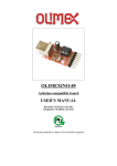
Brain Machine
Created by lady ada
Last updated on 2014-04-07 11:22:41 AM EDT
Guide Contents
Guide Contents
2
Overview
3
Explore altered states of consciousness
3
The Brain Machine!
3
Another great project from Mitch Altman
3
Make it!
5
How to:
5
Preparation
6
Prep
6
Tools
6
Parts list
9
Check your kit!
9
Parts list
9
Solder it!
13
Glasses!
16
Use it!
24
What does the Brain Machine do?
24
How to use it!
24
Battery Life
24
Download
26
Files!
26
Overlays
26
Buy Kit
27
Forums
28
© Adafruit Industries
https://learn.adafruit.com/brain-machine
Page 2 of 28
Overview
Explore altered states of
consciousness
The Brain Machine!
Relax and rejuvenate as your brain synchronizes to a wonderful meditative state, and enjoy
as you hallucinate beautiful colors and patterns from your subconscious mind!
The Brain Machine provides you with a fun, easy way to meditate, all the while being very
photogenic! They work with lights and sounds that pulse at a 14-minute-long meditation
sequence of brainwave frequencies. Your brain synchronizes to this meditation sequence, and
you meditate. It's that easy! And the beautiful colors and patterns you vividly imagine along the
way make it fun and enjoyable.
Build your own Brain Machine to expand your brain's technical skills, then lean back and enjoy
the light show. They are a blast at parties, a fun way to practice meditation and trip out.
The Brain Machine works with blinking lights. Be aware that blinking lights are not good for
some people, especially those prone to seizures!
Another great project from Mitch Altman
TV-B-Gone (http://adafru.it/c1w) inventor Mitch Altman first created the Brain Machine when he
thought to himself "What wo uld happen if yo u co uld play a reco rding o f brain
waves into so meo ne's brain?"
© Adafruit Industries
https://learn.adafruit.com/brain-machine
Page 3 of 28
Being a skilled inventor and engineer, he decided to make such a thing himself! Using a
microcontroller (a small programmable chip) he created a pair of glasses that blink LEDs at the
same frequencies as brain waves. The result is a "Sound and Light Machine" - wearing the
glasses often induces colorful hallucinations while in use, a sense of relaxation afterwards and,
are a fun 14 minute brain trip.
He published this first design in Make Magazine (http://adafru.it/c1x) and it was an instant hit
with hundreds of people building their own.
Now, we've partnered with Mitch to make an updated Brain Machine kit - easier to build, and
comes with all the parts you need. Pick one up at the Adafruit shop to build your own.
© Adafruit Industries
https://learn.adafruit.com/brain-machine
Page 4 of 28
Make it!
How to:
This kit is pretty simple, but you should follow these steps fully so that you'll have no problems!
1. Tools and preparation (http://adafru.it/c1y)
2. Check the parts list (http://adafru.it/c1z)
3. Assemble the kit (http://adafru.it/c1A)
© Adafruit Industries
https://learn.adafruit.com/brain-machine
Page 5 of 28
Preparation
Prep
Learn how to solder with tons of tutorials! (http://adafru.it/aTk)
Don't forget to learn how to use your multimeter too! (http://adafru.it/aZZ)
Tools
There are a few tools that are required for assembly. None of these tools are included. If you
don't have them, now would be a good time to borrow or purchase them. They are very very
handy whenever assembling/fixing/modifying electronic devices! I provide links to buy them,
but of course, you should get them wherever is most convenient/inexpensive. Many of these
parts are available in a place like Radio Shack or other (higher quality) DIY electronics stores.
So ldering iro n
Any entry level 'all-in-one' soldering iron that you might find at your
local hardware store should work. As with most things in life, you get
what you pay for.
Upgrading to a higher end soldering iron setup, like the Hakko FX-888
that we stock in our store (http://adafru.it/180), will make soldering
fun and easy.
Do not use a "ColdHeat" soldering iron! They are not suitable for
delicate electronics work and can damage the kit (see
here (http://adafru.it/aOo)).
Click here to buy our entry level adjustable 30W 110V soldering
iron (http://adafru.it/180).
Click here to upgrade to a Genuine Hakko FX-888 adjustable
temperature soldering iron. (http://adafru.it/303)
So lder
You will want rosin core, 60/40 solder. Good solder is a good thing.
Bad solder leads to bridging and cold solder joints which can be
tough to find.
Click here to buy a spool of leaded solder (recommended for
beginners) (http://adafru.it/145).
© Adafruit Industries
https://learn.adafruit.com/brain-machine
Page 6 of 28
Click here to buy a spool of lead-free solder (http://adafru.it/734).
Multimeter
You will need a good quality basic multimeter that can measure
voltage and continuity.
Click here to buy a basic multimeter. (http://adafru.it/71)
Click here to buy a top of the line multimeter. (http://adafru.it/308)
Click here to buy a pocket multimeter. (http://adafru.it/850)
Flush Diago nal Cutters
You will need flush diagonal cutters to trim the wires and leads off of
components once you have soldered them in place.
Click here to buy our favorite cutters (http://adafru.it/152).
So lder Sucker
Strangely enough, that's the technical term for this desoldering
vacuum tool. Useful in cleaning up mistakes, every electrical engineer
has one of these on their desk.
Click here to buy a one (http://adafru.it/148).
Drill
Either a hand-drill, cordless, bench, or whatever you've got! A 13/64"
drill bit is perfect but a little larger is better than a little smaller.
© Adafruit Industries
https://learn.adafruit.com/brain-machine
Page 7 of 28
Ho t air
You can get hot air from a hair dryer, hot air gun, or even a lighter (be
careful if you're using a lighter!)
Ho t Glue Gun. Or white glue, or even tape.
You'll need this to attach the paper to the glasses, fix the LEDs in
place, etc.
Helping Third Hand With Magnifier
Not absolutely necessary but will make things go much much faster,
and it will make soldering much easier.
Pick one up here (http://adafru.it/291).
© Adafruit Industries
https://learn.adafruit.com/brain-machine
Page 8 of 28
Parts list
Check your kit!
Check to make sure your kit comes with the following parts.Sometimes we make mistakes so
double check everything and email [email protected] if you need replacements!
Parts list
Image
Name
Descriptio n
Part
info rmatio n
Qty
ATTINY25V-10PU
© Adafruit Industries
IC1
Microcontroller
(preprogrammed when
purchased in a kit)
IC1'
8-pin socket
Generic
1
X1
Stereo headphone jack
STX-3100-5N
1
https://learn.adafruit.com/brain-machine
(unprogrammed 1
when not
purchased from
Adafruit)
Page 9 of 28
R-LED,
5mm Diffused Red LED
L-LED
Generic
2
R3, R4 1/4W 5% 47 ohm resistor
Generic
2
Generic
2
Generic
2
B3F-1000
1
1/4W 5% 2.2K resistor
R1, R2
Red, Red, Red, Gold
1.0 uF electrolytic capacitor
C1, C2
6V or greater voltage rating
ON/OFF 6mm tactile switch
6-pin ICSP header
ICSP
© Adafruit Industries
For advanced users who want
Generic
to reprogram the
microcontroller. Don't solder
in until then!
https://learn.adafruit.com/brain-machine
1
Page 10 of 28
BATT
2 x AAA battery holder
PCB
Circuit board
1
Adafruit
Industries
1
Over-ear Headphones
1
Safety Glasses
1
Rainbow Ribbon Wire
The rainbow type makes it
easier to keep track of wires.
1 ft
4" Zip/wire ties
These are bonus parts, in
case you need them for
securing the electronics to
the glasses.
Heat shrink tubing 1/16"
diameter
Paper Overlay
© Adafruit Industries
https://learn.adafruit.com/brain-machine
2
4"
1
Page 11 of 28
AAA batteries
© Adafruit Industries
https://learn.adafruit.com/brain-machine
2
Page 12 of 28
Solder it!
First! Check the Bill of Materials to verify you have all the parts necessary to make the
kit (http://adafru.it/c1z).
Place the PCB in a vise (if you have one), and turn on the soldering iron. Make sure you
have all the tools you'll need to assemble the kit. (http://adafru.it/c1y)
If you don't know how to solder, we suggest checking out the videos in the link above.
They're quite good! Keep them in a window so you can watch and review as you work
through the kit.
The first part we will place is the resistor R4 - this is a small oval tan thing with two
wires (leads) and color stripes. The stripes are yellow violet black which indicates a 47
ohm resistor. This resistor is used to set the brightness of the lightbulbs (LED) for the
right eye. A smaller resistor (less resistance) would make the LED brighter. A larger
resistor would make the LED dimmer.
The resistor goes right in the middle, over the silkscreen text on the PCB that says
R4.
Resistors are no n-po lar which means they don't have a direction: you don't have to
worry about putting it in 'backwards' because they work the same either way.
Bend the resistor into a staple and slip it onto the top of the Printed Circuit Board.
Bend the little leads out so that you can flip over the PCB and the resistor will stay in
place.
Now you'll solder! Place the flat of the soldering iron tip against the silver ring (pad)
and one of the wires of the resistor (lead) at the same time for 2 seconds. This will
heat them both up to 600-700 degrees. Then poke the end of the solder so that it
flows into the hole and forms a solder joint.
Solder joints should be smooth and shiny and fill the entire pad, wicking up to the lead.
you shouldnt be able to wiggle the wire and have it move in the hole.
Once you are happy with the first solder joint, solder the other resistor wire.
You can zoom in by clicking on the photos for a bigger look.
Now we will get rid of all that excess wire. Use your diagonal nippers to clip the wire
just above the end of the solder joint. there should be almost no 'wire' sticking out.
There are another 3 resistors and we'll finish them all up. Place resistor R3 (another 47
ohm yellow-violet-black) resistor right next to R4. This is the resistor that sets the
© Adafruit Industries
https://learn.adafruit.com/brain-machine
Page 13 of 28
brightness for the other eye's LED.
Then place both R1 and R2 they are both 2.2K resistors (red-red-red). These
resistors set the loudness of the earphones for either ear. Using a larger resistor
(more resistance) would make the volume quieter. Using a smaller resisor would
make the volume louder.
Remember it doesn't matter which way you place each resistor since they are nonpolarized. Place them flat against the PCB and bend out the legs.
Solder all the pins of the resistors to the circuit board.
We'll clip the leads again, so that they don't short or interfere with anything else.
Next is the tactile button that is used to tell the microchip in the kit to turn on and off.
The button is also nonpolar (it's just a mechanical switch) so you cant put it in
'backwards' It should snap into place right next to the ON/OFF silkscreen label on the
PCB.
If it doesn't fit, turn it 90 degrees.
It should snap into place and sit flat against the circuit board.
Solder in all four legs of the button. Use plenty of solder because the button needs to
be strongly attached to the PCB or it won't work.
You don't need to clip the leads of the button as they are already short.
Now we will place the chip socket. A socket is a protector. In case you want to replace
the chip or it gets damaged, or something, it's important to have it in a socket. That
way you don't have to permanently solder in the chip.
The socket has a little U in one end. The U should match the U in the silkscreen image
printed on the PCB. In this photo the U is on the right.
If you mess this up, don't try to desolder the socket, instead just keep going and
remember that it is upside down later when it's time to install the chip - the U is just to
help you place the chip properly.
The socket doesn't have long leads to bend, and it doesn't snap into place nicely. You
can tape it to the PCB or if you have sharp fingernails you can sort of bend two corners
in and it'll keep in place while you solder.
© Adafruit Industries
https://learn.adafruit.com/brain-machine
Page 14 of 28
You might want to start by soldering two corner pins. This keeps the socket on
straight while you do the rest.
Solder all 8 of the pins of the socket.
Now we will do the big headphone jack. This is the mechanical connection from the
chip in the brain machine kit to a pair of standard 3.5mm headphones.
The jack will only fit one way. It may snap in or you may want to use a piece of tape to
keep it in place.
You can also hold one finger against the jack while you solder a single pin.
Once one pin is soldered right you can continue.
The headphone pins are a bit long, if you can, clip them down a bit (but cover the pins
as you clip, 'cause you don't want them flying into your eye).
Next are the two electrolytic capacitors C1 and C2. These help smooth the output of
the microcontroller audio generation to make it less squeaky.
Electrolytic capacitors are polarized and must be placed correctly or the circuit will not
work. The longer lead is the positive (+) one and must go into the pad marked with a
+ as shown.
Once you've placed the capacitors in the right way, check them against the photo on
the left, you really want to make sure that the capacitors are in right or they won't work
well!
Solder in the capacitors and clip the long wires.
Now we can place the microcontroller chip. This chip holds the brain machine program
and is 'burned in' here at the Adafruit factory.
The chip has a small black dot in one corner. This small dot should be positioned
© Adafruit Industries
https://learn.adafruit.com/brain-machine
Page 15 of 28
towards the U in the socket (if you placed the socket correctly). Make sure that when
the PCB is oriented as in the photo on the left, you can see the little black dot on the
chip at the lower-left, and the text is 'right side up.'
You may need to squeeze the pins together a little so that they slide into the socket.
When the chip is placed right, it will seat nice and snug into the socket.
(Optional: if you think you would like to re-program your Brain Machine's
microcontroller, solder in the 2x3 pin socker into the 6 pins marked "ISP" on the PCB.
Be sure to place the short leads into the PCB.)
Now you can do a test! This test will check that what you've done so far worked out
well.
Make sure you don't have batteries in the battery holder. Take the battery holder red
and black wires and thread them through the holes near the chip that say Battery
next to them. make sure the red goes in the hole nearer to the chip with a +
(plus/positive) on it and the black wire goes through the hole nearer the chip with a (minus/negative) Now bend the wires around so that the silver ends go through the
solder pads right next to the holes. Do n't so lder these in! Just have them press-fit
there. Click on the photo to the left if you need to see a bigger version of the photo.
Plug the headphones all the way into the jack. Put the headphones on.
Put the two AAA batteries into the holder in the right way. Now press the ON/OFF
button - you should hear tones in both ears.
Now that you've done the test, remove the headphones. Take out the batteries and
put the battery holder away.
Glasses!
Now we will prepare the glasses for the project. We like these dark-tinted safety
glasses. You can use nearly any plastic glasses.
You'll want to mark where your pupils are. If you have a friend, ask them to mark X's
directly over the middle of your eyes while you wear the glasses. If you don't have
a friend handy, try your best to get the X's right in the middle of the lens.
Alternatively, you can print out this convenient glasses
template (http://adafru.it/c1B) -- X marks the spot! (This template will also be
helpful for cutting out the decorative trippy graphics later.)
© Adafruit Industries
https://learn.adafruit.com/brain-machine
Page 16 of 28
Now we'll drill out the holes for the LEDs to fit in. We used 13/64" drill (0.20 inches /
5.2mm) with great success. You can also try a 3/16" drill bit (5mm) but it may be a
little small.
We'll need to wire up the LEDs and batteries to the PCB using wires. While you can
use any wires, we like the rainbow ribbon cables. Each wire is a different color and
the wires are 24 AWG stranded. If you don't use the ribbon cables try to get thin
wires from somewhere else.
One nice thing about the ribbon cable is that if you clip the wires at the end, you can
'tear' off strips.
Use the clip and tear technique to pull off three strips of two wires each. One is
red/brown, another orange/yellow and the last pair green/blue.
Next we will split and strip the wires, twist them and finally tin them!
First, use the nippers to notch the orange/yellow pair and tear them apart about 1"
(2cm).
© Adafruit Industries
https://learn.adafruit.com/brain-machine
Page 17 of 28
Strip the wires about 1/2" (1cm) away from the end, using any kind of wire
strippers. If you mess up and cut the middle wires, just cut the wires short, tear
them apart and try again. You have a lot of wire so there's plenty to practice with.
Once you have the wires stripped, twist them with your fingertips to keep the wire
strands together.
Now we will tin the ends of the wire. Wire needs to be tinned to make good
contact. Tinning basically means melting a little solder onto the wires before we
attach it to something else. It keeps the strands from flying around and also makes
for better solder connection.
We'll use a 3rd-hand tool to hold the wires steady. Melt a little solder onto the iron
tip. Use the soldering iron side to sweep the wire strands while also melting some
more solder on. You will see the solder wick into the strands and strengthen the
wire.
Now we will wire up the LEDs that blink in front of the eyes. LEDs are Light Emitting
Diodes - the light emitting part is pretty easy to understand. The Diode part is a
little more difficult, but basically a diode is a component that only works 'one way'.
Like the capacitors, we have to keep track of which pin is which or the LED won't
turn on and light when we want it to.
The good news is that if you power an LED backwards, nothing bad will happen to
destroy it (it just won't light up).
For LEDs, the lo nger lead is po sitive.
Cut tbe sho rter wire of the LED (negative lead) so that only about 1/4" (half a cm)
is left.
Then tin it just like you did with the wires, so there is some solder on the wire lead.
Because there is already solder on the LED and wire, you should be able to hold the
yellow wire to the short lead and heat it up with the iron and they'll melt together
and hold.
© Adafruit Industries
https://learn.adafruit.com/brain-machine
Page 18 of 28
Clip the remaining LED wire and solder the orange wire to it.
When both leads of the LED are soldered you can go back and melt more solder
over them if they're not solidly connected (but be sure to hold the wire in place as
you solder, or it will fall off).
Now we'll do the other eye's LED. Cut, strip and tin the green/blue wire pair just like
the orange/yellow.
Solder the blue wire to the positive (longer) LED pin and the green wire to the
negative (shorter) LED pins.
Finally, bend both LEDs (gently and only once) so they are at right angles to the
wire. It doesn't matter which way they are bent. The easiest way to do this is to
hold the LED in one hand and use a finger to bend the wires.
Now we'll attach the LEDs to the glasses!
Place the orange/yellow LED in the left eye and the green/blue LED in the right eye
drill hole. Be sure to push the LEDs into the glasses from the front (so they will
shine in to your eyes).
Use tape on the opposite side to keep the LEDs in place.
Use hot-glue, white glue, epoxy, silicone adhesive, rubber cement, or your
adhesive of choice, to glue the LEDs into place from the inside.
We think hot-glue or epoxy will work best. Superglue may not work, be careful not
to glue everything!
If necessary glue on the back (outside) as well - especially if the hole is large
enough that the shoulder of the LED goes through.
Now it's time to extend the battery pack!
We're going to stick the batteries on the right-side arm of the glasses to balance
out the PCB on the left. Problem is, the wires aren't long enough to reach all the
© Adafruit Industries
https://learn.adafruit.com/brain-machine
Page 19 of 28
way. So we're going to make wire extenders!
First thing, cut two pieces of heatshrink, at least 1/2" (1 cm) long and slip them onto
the battery pack wires - we'll use them later.
Take the third wire-pair (red/brown) and strip/tin it on both sides just like you did
before.
Solder the red wire to the red wire of the battery pack.
Next solder the black wire to the brown wire. Make sure the heat shrink is on the
battery pack wires but out of the way so you don't accidentally heat them up
before it's time.
Once the wires are soldered, slip the heatshrink so that it covers the soldered
joints.
Then heat the heatshrink with something hot. You can use a heat-gun, hairdryer,
soldering iron (rub gently), or even a lighter as long as you don't catch the whole
thing on fire (stay a few inches away).
The heatshrink protects the wires and keeps them from shorting to each other. It
also makes the solder joint stronger.
Squeeze a big blob of hot glue on to the left arm of the glasses and stick the
battery pack on, making sure that the wires from the battery pack are facing the
front of the glasses.
IMPORTANT: Fold the arms of the glasses before gluing in the following steps.
Use tape to attach the red/brown, orange/yellow and blue/green wires to the top
edge of the glasses so they run together.
© Adafruit Industries
https://learn.adafruit.com/brain-machine
Page 20 of 28
As in the photo, make sure that the arms of the glasses are folded, and use your
adhesive of choice to glue the wires to the top of the glasses. The tape will keep
the wires in place while the glue hardens.
Turn over the glasses, we'll be gluing the PCB to the right arm -- but not yet!
First we will solder the wire harness to the PCB.
Start with the two power wires (red/brown). Place the PCB on the arm, maybe use
tape to hold it in place, and cut the red/brown wire pair so that you have plenty of
wire to solder it to the Battery terminals (but not so much it's a big mess) -- about
2" extra length is sufficient. (I cut it a little shorter than necessary, give yourself
plenty of space!)
Cut, trim, split, strip and tin the wires. Then slide the Red wire through the hole
marked + (positive, plus) and the Bro wn wire through the hole marked - (negative,
minus).
Then bend the wires into the silver pads.
Solder the Red wire to + and the Brown wire to -.
You can do a quick test now by putting AAA's into the holder and the headphone
into the headphone jack. You should be able to hear the tones when you press the
ON/OFF button.
© Adafruit Industries
https://learn.adafruit.com/brain-machine
Page 21 of 28
Cut the Orange/Yellow and Green/Blue wires so that there is plenty of slack for
them to reach the LED solder holes on the right edge of the PCB. Be sure to have
enough wire so that you can fold the arms of the glasses.
Cut, trim, split, strip and tin the four wires.
Insert the wires as follows:
Yellow -> LOrange -> L+
Blue -> R+
Green -> RUse the same over-under technique to place the wires. This time, don't solder
them in yet! We'll do a test to make sure we have the right polarity. Insert AAA
batteries and press the buton, you should see both LEDs blink red. If one does not
blink, try flipping the wires between the + and - pins in case it's in backwards. If so,
just solder in the wires so that they work, don't try to desolder the LED.
After you've tested the board, remove the AAA batteries and solder in the four
wires.
Cut the excess leads from the four wires.
Now we'll attach the PCB. Spread some hotglue, epoxy, silicone adhesive, etc, on
to the right arm.
Then press the PCB on so that there's enough wire slack for the glasses to fold. (If
you like, you may use the included zipties to help secure the PCB to the glasses.)
OK you're done with building the Brain Machine kit...now you can decorate it!
We included a trippy color graphics overlay for you to use. We have other designs
you may like on the download page (http://adafru.it/c1C), or experiment with
whatever you have around the house!
© Adafruit Industries
https://learn.adafruit.com/brain-machine
Page 22 of 28
whatever you have around the house!
If you print out this convenient glasses template (http://adafru.it/c1B) it will make it
easy to cut out the overlays to glue on to the front of your glasses. And, if you
used this template to drill the holes in the glasses, the template will also show
where to cut holes (for the LEDs) in the overlay.
You can glue the overlay on to the glasses using hot glue, or your adhesive of
choice. (Be aware that the overlay will not lie flat on the glasses due to the
curvature of the glasses.)
Now you are ready to rock out, read the user manual for tips on how to best-enjoy
your kit! (http://adafru.it/c1C)
Do n't Fo rget: The Brain Machine wo rks with blinking lights. Be aware
that blinking lights are no t go o d fo r so me peo ple, especially tho se
pro ne to seizures!
© Adafruit Industries
https://learn.adafruit.com/brain-machine
Page 23 of 28
Use it!
What does the Brain Machine do?
The Brain Machine provides you with a fun, easy way to meditate, all the while being very
photogenic! They work with lights and sounds that pulse at a 14-minute-long meditation
sequence of brainwave frequencies. Your brain synchronizes to this meditation sequence, and
you meditate. It's that easy! And the beautiful colors and patterns you vividly imagine along the
way make it fun and enjoyable.
How to use it!
Using the Brain Machine kit is easy!
1.
2.
3.
4.
Put on the headphones and glasses
Close your eyes gently
Press the ON/OFF button on the right side PCB
Meditate, Hallucinate, and Trip Out and enjoy, with your eyes gently closed the entire
time, for as long as you like.
5. The Brain Machine will automatically turn itself off when the trip sequence is complete.
6. If you want to stop the sequence early, just press the ON/OFF button again (or just
remove the headphones and glasses).
The Brain Machine works with blinking lights. Be aware that blinking lights are not good for
some people, especially those prone to seizures!
Some peoples' eyes are more sensitive to bright lights than others. Using the Brain Machine
should be a great experience. They should also be comfortable. If the blinking lights are
uncomfortable for you, then there are two ways to reduce the brightness to make them less
intense:
If at any time you want to make the experience less intense, simply slide the glasses
down your nose until you feel comfortable.
Use every-day masking tape to cover the red LEDs to make them less bright. Just keep
putting tape over the LEDs until they are not too bright.
Battery Life
The Brain Machine Kit comes with 2 AAA standard alkaline batteries. These should last for
© Adafruit Industries
https://learn.adafruit.com/brain-machine
Page 24 of 28
hundreds of trip sequences. If you ever need to replace the batteries just use any AAA's from
the store. The brain machine works fine with low cost 'economy' batteries so you don't need to
spend a lot for the expensive batteries.
© Adafruit Industries
https://learn.adafruit.com/brain-machine
Page 25 of 28
Download
Files!
You can get the latest schematics, board layouts and firmware from the github
repository (http://adafru.it/c1D).
The hardware files are released under CC BY-SA (attribution, share alike).
Overlays
Snazzy up your brain machine with the original graphix overlay or many other 60's style designs
you can print and use (http://adafru.it/c1E).
There are also some templates that may be handy for drilling the eye-LED holes:
http://www.tvbgone.com/mfaire/slm/GlassesTemplate1.pdf (http://adafru.it/c1B)
© Adafruit Industries
https://learn.adafruit.com/brain-machine
Page 26 of 28
Buy Kit
Buy Kit (http://adafru.it/aJD)
© Adafruit Industries
https://learn.adafruit.com/brain-machine
Page 27 of 28
Forums
Forums (http://adafru.it/forums)
© Adafruit Industries
Last Updated: 2014-04-07 11:22:44 AM EDT
Page 28 of 28