1
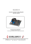
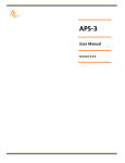
Standards Converter
for
Mechanical Television
Model’s SC
User and Technical
Manual
Copyright 2006-9 Aurora Design LLC.
Revision 1.0
23 April, 2007
All specifications subject to change
www.tech-retro.com
Introduction
Introduction
This manual covers the operation and technical aspects of the Single-Standard
Converter for mechanical television. The Converter is designed to accept an NTSC or
PAL/SECAM video signal and convert to one of several different output standards
depending on the model. The converted video is sent to a composite video output
connector.
Due to the nature of mechanical television it is assume that the user has a good
understanding of what is required to operate such a device in conjunction with this
converter, such as an ppropriate lamp (Neon, LED, etc) and a lamp driver that
accepts the video output signal from this converter. No attempt is made in this
document to describe such a driver and it’s operation.
Features
• Compact, low power, surface mount design
• Front panel Status LED
• Internal user switch selectable options control
• Extremely stable output: +/- 3% levels, +/- 50ppm timing
• Output clock line locked to input clock for perfect conversions
• 10 bit video D/A for greater than 54dB dynamic range
• 100K gate equivalent FieldProgrammableGateArray
• EEPROM memory for FPGA firmware, field upgradeable
• Extremely accurate algorithms used for conversions
• Two full frame memory for stable output regardless of input
• Automatic Sleep Mode for low power standby operation
• Versatile I/O:
- Composite Video Input (NTSC/PAL, 1Vpp, 75 ohm)
- Composite Video Output (various standards depending on model, 1Vpp, 75 ohm)
- DC power (7-14Vdc, 100ma)
3
Introduction
Front Panel
The front panel is shown below:
Composite
Video
Input
Status
LED
Composite Video Input:
The Composite video input signal required depends on the operating mode and
model of the converter. A video source conforming to the NTSC or PAL/SECAM
video standards must be supplied to the Composite (RCA or BNC) input connector.
The unit accepts either standard, selectable through an internal option switch.
Status LED:
The status LED conveys the current operating state of the converter.
Slow Flashing: No video input signal detected. Default image will be output.
Solid:
Converter locked to video input. Normal operation.
Pulsating:
Converter in low power Sleep mode.
4
Introduction
Rear Panel
The rear panel is shown below:
Composite
Video
Output
9Vdc
Input
Composite Video Output:
This RCA or BNC connector provides the video output from the converter. This
output should terminate into a 75 ohm load. For complete information about the
characteristics of this output, please refer to the Specifications section found later in
this manual. This output will typically connect to a user supplied lamp driver for the
mechanical television.
Power:
The converter requires a power source of between 7.0 and 14 volts DC at 100
mA. A 9 volt DC power supply is recommended to reduce power consumption.
Voltages over 16 volts will damage the unit. The unit has a reverse polarity diode in
series with the input, so it will not be damaged by reversal of polarity. The unit uses a
standard 2.1mm X 5.5mm, center positive, coaxial power connector as found on
most consumer electronic equipment.
Internal Options
The internal Options switch and AM Audio RF Carrier control are shown below:
5
R30
1 2 3 4
ON
R10
R9
Back of unit
(Outputs)
S1
R8
L2
Introduction
Programing
Port
R3
U1
Option
Switch
U2
C32
R4
Front of unit
(Inputs / LED)
The internal Option Switch S1 has four controls allowing the user to set the
operating mode of the converter. In order to change the switch settings, the cover
must be removed from the unit. To do this, first remove all cables from the unit,
including the power cable. Place the unit on it’s top, and remove the two, small
phillips screws from the bottom. Flip the unit back over, and remove the top.
Caution! In the subsequent steps, make sure you are touching one of the outer
metal rings on the phono or RF connectors to discharge any static electricity that
may be present before proceeding. There are static sensitive devices inside the
converter that can be damage if subjected to a static discharge. Failure to follow this
procedure will result in damage to the unit!
Using a small tool such as a paper clip, carefully slide the desired switch to it’s
new position being careful to not put an undue amount of force on the switch that
might damage it or the circuit board. Once the desired switch settings have been
achieved, replace the cover on the unit, and reinstall the two phillips screws.
Position 1 - Input Standard Select:
This switch is used to control the Input Standard of the converter. In the OFF
position the converter will accept a PAL input video signal. In the ON position the
converter will accept a NTSC input video signal.
6
Introduction
Position 2 - Output Standard Select:
This switch is used to control the Output Standard of the converter. For the
SC30/32 model, in the OFF position a 32/12.5p NBTV type signal is output. This
includes the appropriate line and frame sync signals. In the ON position a 30/12.5p
Baird type signal is output. This includes the three elongated pixels on each side of the
image.
Position 3 - Output Invert:
This switch is used to select the output mode of the converter between normal and
inverted. In the OFF position the converter will output a normal, positive video signal.
In the ON position the converter will invert the output. This can be useful to match
the polarity of the external lamp driver.
Position 4 - Output Gamma:
This switch is used to select the output mode of the converter between gamma
correted and straight video. Since modern video is pre-corrected at the source to
compensate for the gamma of CRT’s, and since most lamps used for mechanical
television are linear (Neon, LED, etc) gamma correction needs to be provided to
correct the video. This feature performs the correction accurately in the converter so
it is not required in the lamp driver. In the OFF position the internal gamma
correction is eneabled. In the ON position the internal gamma correction is disabled.
Operating Modes
Normal Full Operating Mode:
When valid video is present the Status LED will show a Solid light, and the unit
will output converted video on the composite output connector. This is the most
common operating mode.
Default Mode:
When no valid video is connected to the composite input, the unit will output a
default image. This can be used to verify operation of the unit, or aid in setup of the
television.
Sleep Mode:
Since no power switch is supplied on this unit, an automatic Sleep Mode will be
7
Introduction
entered whenever the video input is not present for more than 1 hour. With this
feature, the standards converter is shut down, along with the video output. Only the
video decoder is left active to signal when a valid video input is again supplied to the
unit to wake it up.
Typical Connections
In normal usage, a user supplied power adapter is connected to the converter and
to the AC power source. A valid NTSC or PAL/SECAM video source should also
be connected to the video input. The video source can be anything from a VCR to a
DVD to an off-air broadcast. The video output can then be connected to the input of
a user suplied lamp driver. This driver needs to take the video output signal from the
converter and power the apropriate lamp. (Neon, LED, etc). The driver should
provide for brightness (level) and contrast (gain) controls to adjust the video signal for
proper operation of the lamp. The brightness control can be used to properly setup
for blacks while the contrast control can setup for peak whites.
Typically some means of synchronization is required for the television to avoid
having the user constantly adjuat the speed and phase of the motor to keep the image
centered and phased. For the NBTV standard, this is done through the insertion of
standard type line sync pulses in the video, with the pulse missing on line one for
frame synchronization. A properly equipped NBTV television will lock the the output
of the converter with no other adjustments necissary. For televisions like the Baird
which used an AC/DC motor and a snychronous phonic coil, the video output signal
from the comnverter needs to be filtered and fed through an appropriate amplifier to
the phonic coils on the television. This will lock the television to the converter but the
user will still need to phase (center) the image manually.
Since the converter contains multiple full frames of video memory, the output
signal will always be stable regardless of the video input signal. Normally a
mechanical television would require relocking and rephasing each time the video
input signal changed, but the converter eliminates this entirely. Once the television is
locked to the conveter, it should remain so.
The use of high quality video cables is recommended for best results. Cables
conforming to 75 ohm impedance should be used on the video inputs and outputs.
If all the above steps have been properly performed, there should now be a solid
status light on the front panel of the converter indicating a locked video signal as
described previously, and a stable image on the television.
To help aid in setup, when no video input is presented to the converter, it will
output a default image. This can be useful in making final adjustments to the
television.
Video content is important to consider when dealing with mechanical televisions
due to the small size and low resolution. Close ups that are centered in the video
make for better viewing on the mechanical television. For standards with low aspect
ratio such as Baird (3:7) and NBTV (2:3) only the center protion of the input video is
converted to maintain the correct ratio.
8
Introduction
Theory of Operation
In order to convert between different video standards, spatial and temporal
correction are required. Spatial correction involves changing the resolution, size and
aspect ratio of the incoming video to the output video format. This can be easily
achieved through standard digital methods utilizing scalers and FIR filters. This will be
discussed in detail. Temporal correction involves changing the frame rate of the
incoming video to match the outgoing video.
It was decided that no off the shelf components existed that would provide the
desired functionality, so a FieldProgrammableGateArray, or FPGA, was chosen to
provide all the digital functionality. By adding input/output circuitry, memory, and
ancillary circuitry to the FPGA, the entire system could be realized. The basic
building blocks to the design are; FPGA, video decoder (ADC), and multiple power
supplies. A brief description of each part follows:
FPGA:
Xilinx XC3S100E-4VQ100
100K gate equivalent
72Kb block RAM
1.2V Core / 2.5V Aux / 3.3V I/O
Video Decoder:
TI TVP5150A
9bit ADC’s, 2X Over-Sampled
Line Locked Clock
4 Line Adaptive Comb Filter
Multiplexed 8bit YCrCb output bus
Video DAC:
Proprietary Design
10bit effective DAC
35 MSPS maximum conversion rate
56 dB SNRs
Topology
A block diagram of the circuitry is shown below:
Composite
Input
Video
ADC
and
Decoder
FPGA
Field
Memory
9
Video
PLL
Video
DAC,
Filter
and
Driver
Composite
Output
Introduction
The incoming video is digitized and processed by the TVP5150A using a
14.318MHz reference crystal to the ITU-601 (formerly known as CCIR601)
specification. All internal timing is generated using this crystal. The video is quantized,
processed for brightness, contrast, chroma gain and hue, among others, and output at
the ITU rate of 27MHz on an 8 bit, time multiplexed bus, with alternating luma and
chroma samples. No other signals are required from this circuit as the ITU
specification describes a method for encrypting the horizontal and vertical timing
information directly into the digital data using timing reference makers, or TRS codes.
A brief description of the ITU-601/656 specification is as follows:
Fundamental quantization frequency: 13.5MHz
Pixel Resolution: 720 H x 486 V NTSC / 720 H x 576 PAL
Image Aspect Ratio: 4:3
Pixel Aspect Ratio: 1.1 NTSC / 0.9 PAL
Horizontal Frequency: 15,734 Hz NTSC / 15,625 Hz PAL
Vertical Frequency: 29.97 Hz NTSC / 25 Hz PAL
Clocks per Line: 1716 NTSC / 1728 PAL (27MHz clock)
Clocks per Frame: 900900 NTSC / 1080000 PAL (27 MHz clock)
Note that the vertical frequency is 29.97Hz for NTSC, not 30Hz as
expected. This is due to the NTSC color system that was first ratified in 1953.
All monochrome television transmissions prior to this standard used exactly
30Hz, or 30 frames per second, so as to be in sync with the AC line frequency.
This is done to reduce distortions in the image due to induced AC fields or
“hum” from the power supplies of these early sets. In order to devise a
“compatible” color system that would show a monochrome signal on existing
sets, RCA proposed a method of modulating the color components of the
video signal onto a subcarrier in the video. For reasons beyond the scope of
this manual, a frequency needed to be chosen so that no standing patterns in
the color signal would result. This required lowering the vertical frequency
from 30Hz to 29.97Hz. While this change caused no adverse side effects on
televisions, it has created a legacy of problems for modern video equipment.
Instead of being able to use integer numbers like 24, 25 and 30, we now have
to include 29.97 which makes many calculations and conversion extremely
difficult. For digital processing, the ratio 1000/1001 has been established as the
conversion between 30 and 29.97 video.
The digital video data is then routed to the FPGA where it is further processed.
The data is sent to the internal field memory in round robin fashion. The field
memory is large enough to hold two frames of video, so there is always enough data
to keep an uninterrupted flow to the output. The video data is scaled prior to storing
in the field memories. This scaling is done with a multi-tap FIR filter for the horizontal
downscaling, and averaging for the vertical. Extra processing like that to stretch the
outer three pixels on each side of a Baird image is also done at this time.
All processing is done synchronous to the ITU clock. Since this clock is much
higher than required for mechanical television rates, it is also used to generate the
output video. Using the same ITU clock, a video timing generator, or flywheel is
10
Introduction
created in the FPGA to generate all timing signals for the model’s output standard.
All horizontal, vertical, pixel count and line count generation is done in this process.
This is the main “heartbeat” process for the entire design.
Using these timing signals, the video data that was stored in the field memory
synchronous to the incoming ITU video clock can now be clocked out.
With all the above timing now generated, the output video can be created. The
signals from the flywheel are routed to the video output DAC at the appropriate
times in the signal, while the processed video from the partial-field memory is routed
to the video DAC during the active portions of the video signal. The DAC is run at a
two times over sampled rate to reduce filtering requirements, and increase SNR.
The video is then filtered and buffered before being sent to the composite output
connector.
Updating Firmware
If it ever becomes necessary to update the firmware in the unit, this can be
accomplished through the programming port next to the Option Switch as previously
shown. The connector is a standard 8 pin, double row, 2mm connector. A custom
cable with a mating connector is used in conjunction with a Xilinx Parallel III, Parallel
IV or USB Platform download cable and the appropriate software. A full description
of the hardware, software, and procedure to FLASH the unit can be found in the
supplemental programming guide for the converter.
11
Specifications
Specifications
Video Input:
Supported Standards:
NTSC 29.97fps / PAL 25fps / SECAM 25fps
Video Quantization:
9bit A/D, 8 bit data
Video Input:
Composite - 1Vpp, 75 ohm impedance
Video Output:
Video Output:
Composite - 1Vpp into 75 ohms
Video Quantization:
10 bit Effective D/A
Video Levels:
+/- 3% of output standard
Video Timing:
+/- 50 ppm, Line/PLL locked, < 2ns jitter typical
Video SNR:
56dB typical
General:
Dimensions:
2.60” X 2.60” X 1.00” (66mm X 66mm X 25mm)
Weight:
2.0oz (57g)
Power Requirements:
9Vdc typical, 7-14Vdc maximum
1.0 watts typical (Full Operation)
0.75 watt typical (Sleep Mode)
Humidity:
20% - 80% non-condensing
Temperature:
10C - 45C ambient (50F - 110F)
12
Supported Conversions
Supported Conversions
NTSC/PAL to 32/12.5p NBTV:
Image / Pixel Aspect Ratios:
Pixel Clock:
Active Pixels / Lines:
2:3 / 0.33
27.0 MHz
32 (cropped 60) / 120 - NTSC Input
32 (cropped 60) / 125 - PAL Input
Horizontal / Vertical Frequency: 12.488 Hz / 400 Hz - NTSC Input
12.5 Hz / 400 Hz - PAL Input
Scan Type:
Mechanical Progressive Bottom to Top, Right to Left
Video Characteristics:
26 KHz, 1Vpp into 75 ohms
70/30 video/sync ratio
NTSC/PAL to 30/12.5p Baird:
Image / Pixel Aspect Ratios:
Pixel Clock:
Active Pixels / Lines:
3:7 / 0.49
27.0 MHz
30 (cropped 90) / 120 - NTSC Input
30 (cropped 90) / 125 - PAL Input
Horizontal / Vertical Frequency: 12.488 Hz / 375 Hz - NTSC Input
12.5 Hz / 375 Hz - PAL Input
Scan Type:
Mechanical Progressive Bottom to Top, Right to Left
Video Characteristics:
25s KHz, 1Vpp into 75 ohms
13
Available Models
Available Models
Model No. SC30/32
NTSC/PAL to 30/12.5p Baird and 32/12.5p NBTV
14
Firmware Revision History
Firmware Revision History
Revision 1.0, April 23, 2007:
1) Initial release.
Note: Hardware/Firmware revision level can be found on bottom label of unit.
15