1
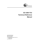
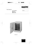
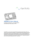
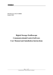
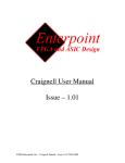
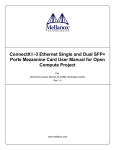
Xilinx® Spartan™-3E Evaluation Kit User Manual Table of Contents 1.0 Introduction ............................................................................................................................................................................... 4 1.1 Description............................................................................................................................................................................ 4 1.2 Features ............................................................................................................................................................................... 4 1.3 Demo Applications................................................................................................................................................................ 5 1.4 Ordering Information............................................................................................................................................................. 6 2.0 Hardware .................................................................................................................................................................................. 7 2.1 Spartan-3E FPGA................................................................................................................................................................. 7 2.2 Configuration ........................................................................................................................................................................ 8 2.3 Creating a .HEX file ............................................................................................................................................................ 10 2.4 Programming SPI FLASH................................................................................................................................................... 11 2.5 Avnet USB Utility ................................................................................................................................................................ 11 2.6 Jumper Settings.................................................................................................................................................................. 13 2.7 Clocks................................................................................................................................................................................. 15 2.8 On-board Display (2 Character Alphanumeric LED)........................................................................................................... 16 2.9 DIP & Push-button Switches............................................................................................................................................... 16 2.10 LEDs .............................................................................................................................................................................. 17 2.11 Memory .......................................................................................................................................................................... 17 2.11.1 SPI Flash........................................................................................................................................................................ 17 2.12 Communication (RS-232, USB 2.0) ...............................................................................................................................18 2.12.1 RS-232 ........................................................................................................................................................................... 18 2.12.2 USB 2.0.......................................................................................................................................................................... 18 2.13 I/O Connectors ............................................................................................................................................................... 20 2.14 Power ............................................................................................................................................................................. 22 3.0 Software/BSP.......................................................................................................................................................................... 22 3.1 What is included ................................................................................................................................................................. 22 4.0 List of Partners........................................................................................................................................................................ 23 Figures Figure 1 - Virtex-4 FX Evaluation Board Picture......................................................................................................................................... 5 Figure 2 - Spartan-3E Evaluation Board Picture......................................................................................................................................... 6 Figure 3 - Spartan-3E Evaluation Kit Block Diagram .................................................................................................................................. 7 Figure 4 - Boundary Scan Mode Selection via JP6 .................................................................................................................................... 8 Figure 5 - Configuration Connections – Par3 ............................................................................................................................................. 9 Figure 6 - Configuration Connections – Par IV ........................................................................................................................................... 9 Figure 7 - Select Target Board ................................................................................................................................................................. 12 Figure 8 - USB Utility GUI......................................................................................................................................................................... 13 Figure 9 - Default Jumper Placement ....................................................................................................................................................... 15 Figure 10 - Barrel Power Connector "J5".................................................................................................................................................. 22 Copyright © 2005 Avnet, Inc. AVNET and the AV logo are registered trademarks of Avnet, Inc. AVNET AVENUE and AVNET AVENUE & Design are trademarks of Avnet, Inc. All other brands are property of their respective owners. Avnet Design Services Released 2 of 23 Rev 1.0 08/09/2005 Literature # ADS-005204 Tables Table 1 - Ordering Information ................................................................................................................................................................... 6 Table 2 – Spartan-3E Attributes by Density................................................................................................................................................ 7 Table 3 - FPGA Configuration from PROM/JTAG … Jumper Setting......................................................................................................... 8 Table 4 - JTAG Headers (Par-3 & Par-4) Pin-Out ...................................................................................................................................... 8 Table 5 – J6 Header (SPI) Pin-out ........................................................................................................................................................... 11 Table 6 – Available GCLK Sources .......................................................................................................................................................... 15 Table 7 - Ethernet PHY Modes................................................................................................................................................................. 16 Table 8 – DIP switch FPGA Pin-out ......................................................................................................................................................... 16 Table 9 – Push button FPGA Pin-out ....................................................................................................................................................... 17 Table 10 - LED FPGA Pin-out .................................................................................................................................................................. 17 Table 11 - SPI FPGA Pin-out ................................................................................................................................................................... 17 Table 12 – RS-232 FPGA Pin-out ............................................................................................................................................................ 18 Table 13 – RS-232 Connector Pin-out ..................................................................................................................................................... 18 Table 14 - USB Interface FPGA Pin-out ................................................................................................................................................... 20 Table 15 - Header "J1" Pin-out................................................................................................................................................................. 21 Copyright © 2005 Avnet, Inc. AVNET and the AV logo are registered trademarks of Avnet, Inc. AVNET AVENUE and AVNET AVENUE & Design are trademarks of Avnet, Inc. All other brands are property of their respective owners. Avnet Design Services Released 3 of 23 Rev 1.0 08/09/2005 Literature # ADS-005204 1.0 Introduction The purpose of this manual is to describe the functionality and contents of the Spartan-3E Evaluation Kit from Avnet Design Services. This document includes instructions for operating the board, descriptions of the hardware features and explanations of the example projects. 1.1 Description The Spartan-3E Evaluation Kit provides a platform for engineers designing with the Xilinx Spartan-3E FPGA. The board provides the necessary hardware to not only evaluate the features of the Spartan 3E but also to implement user applications with a basic set of peripherals. Example projects are provided to help the user understand the design tool flow and leverage from known functional designs. 1.2 Features FPGA — Xilinx XC3S100E-TQ144 Spartan-3E FPGA Board I/O Connectors — 50-pin header for user I/O — 8 discrete LEDs — 2 push-buttons — 4-position DIP-switch — Dual character alpha numeric display Memory — ST Microelectronics SPI serial FLASH Communication — USB 2.0 — RS-232 serial port Power — USB or 5V wall-mount (not included) — Texas Instruments TPS75003 triple supply Configuration — SPI serial FLASH to FPGA — USB download utility — Support for Xilinx Parallel Cable IV — Fly-wire support for and Xilinx or compatible cable Copyright © 2005 Avnet, Inc. AVNET and the AV logo are registered trademarks of Avnet, Inc. AVNET AVENUE and AVNET AVENUE & Design are trademarks of Avnet, Inc. All other brands are property of their respective owners. Avnet Design Services Released 4 of 23 Rev 1.0 08/09/2005 Literature # ADS-005604 J5 RS232 J3 U11 6 J4 JP7 JP3 DESIGN SERVICES electronics marketing SW2 SW1 U1 U3 U2 U10 JR1 JP6 6 JP2 J1 Figure 1 - Virtex-4 FX Evaluation Board Picture 1.3 Demo Applications The Spartan-3E Evaluation Kit from Avnet Design Services comes with example projects designed in Xilinx ISE. The example projects help the user get started by leveraging already tested and functional designs. The example projects that will be discussed in detail later in this document are listed below. *Note: There may be additional demos which were developed after the printing of this document. applications, please contact your local Avnet FAE. For additional demo Segment Test Project — Display count value on segment display — Provide test message over RS232 — Source Code Included Copyright © 2005 Avnet, Inc. AVNET and the AV logo are registered trademarks of Avnet, Inc. AVNET AVENUE and AVNET AVENUE & Design are trademarks of Avnet, Inc. All other brands are property of their respective owners. Avnet Design Services Released 5 of 23 Rev 1.0 08/09/2005 Literature # ADS-005604 Figure 2 - Spartan-3E Evaluation Board Picture 1.4 Ordering Information The following table lists the evaluation kit part numbers and available software options. For more information, visit the Internet link at http://www.em.avnet.com/ads or www.em.avnet.com/spartan3e-evl Part Number ADS-XLX-SP3E-EVL100 Hardware Xilinx Spartan-3E Evaluation Kit with an XC3S100E ADS-BASEX-BUNDLE ISE BaseX (only available with purchase of the above part number) Table 1 - Ordering Information Copyright © 2005 Avnet, Inc. AVNET and the AV logo are registered trademarks of Avnet, Inc. AVNET AVENUE and AVNET AVENUE & Design are trademarks of Avnet, Inc. All other brands are property of their respective owners. Avnet Design Services Released 6 of 23 Rev 1.0 08/09/2005 Literature # ADS-005604 2.0 Hardware This section of the manual describes the hardware of the Spartan-3E Evaluation Board. The hardware was designed with the Spartan3E FPGA as the focal point. The block diagram is shown in Figure 8. Configuration P4 JTAG Config/JTAG SPI Serial EEPROM RS232 Switches: Dip(4) P.B.(2) Xilinx USB2.0 HS SPARTAN 3E XC3S100E-VQG144 (Lead Free?) 8 LEDs Cypress CY7C68013A 2x Alpha Display 50 Pin HDR Clock: 100MHz Figure 3 - Spartan-3E Evaluation Kit Block Diagram 2.1 Spartan-3E FPGA The Spartan-3E Evaluation Board was designed to support the Spartan-3E FPGA in the 144-pin package (TQ144). This package supports two densities 3S100E and 3S250E though initially only the 3S100E will be offered in a product. Table 2 describes the attributes of the Spartan-3E device based on density. Spartan3E Part System Gates Logic Cells BlockRAM (bits) BRAM Dedicated Multipliers DCMs XC3S100E XC3S250E 100K 250K 2,160 5,508 72K 216K 4 12 4 12 2 4 Max User I/O (144 package) 108 108 Table 2 - Spartan-3E Attributes by Density Copyright © 2005 Avnet, Inc. AVNET and the AV logo are registered trademarks of Avnet, Inc. AVNET AVENUE and AVNET AVENUE & Design are trademarks of Avnet, Inc. All other brands are property of their respective owners. Avnet Design Services Released 7 of 23 Rev 1.0 08/09/2005 Literature # ADS-005604 2.2 Configuration The Spartan-3E Evaluation Board supports Boundary-scan (JTAG) and SPI programming methods. In addition, the user may use the Avnet USB utility to configure the FPGA and/or SPI flash device. Configuration Mode (M2 : M1 : M0) SPI DEFAULT (0:0:1) USB CCLK En JP4 Mode Select JP6 Notes DEFAULT FPGA provides SPI protocol to read from the Flash. FPGA will not attempt configuration over SPI or other means. It may be programmed directly over the JTAG interface. In this mode the FPGA is configured over USB from a Host PC. A Windows utility is provided. Boundary Scan (1:0:1) USB (NA) Table 3 - FPGA Configuration from PROM/JTAG … Jumper Setting 2.2.1 Boundary Scan Programming the Spartan-3E FPGA via Boundary-scan requires a JTAG download cable (not included in the kit). The Spartan-3E Evaluation Board has connectors to support both the flying leads connection of the Parallel Cable III and the ribbon cable connection of the Parallel Cable IV. These connectors are labeled “J4” and “JP7” respectively. When programming the FPGA via the JTAG interface, it is good practice to place the device in Boundary Scan mode. This may be accomplished using the Mode select jumper JP6. With JP6 off, the mode pins M[2:0] will be 001 which enables SPI programming mode. With JP6 installed, the mode pins M[2:0] will be 101 which enables boundary scan mode. Note that power should be removed when changing the programming Mode. For Boundary Scan mode, place a jumper at JP6 Figure 4 - Boundary Scan Mode Selection via JP6 JTAG Header (J4) J4 is a 6x1 standard 0.1” header and is intended for use with flying leads, such as those of the Xilinx Parallel Cable 3 (PC3) downloading/debugging cable. Connect the leads as indicated in Table 4 below for “J4” as demonstrated in Figure 5. Signal Name VCC TDI TDO TMS TCK GND Par-3 (J4) pin 1 2 3 5 4 6 PAR-4 Ribbon (JP7) pin 2 10 8 4 6 1,3,5,7,9,11 or 13 Table 4 - JTAG Headers (Par-3 & Par-4) Pin-Out Copyright © 2005 Avnet, Inc. AVNET and the AV logo are registered trademarks of Avnet, Inc. AVNET AVENUE and AVNET AVENUE & Design are trademarks of Avnet, Inc. All other brands are property of their respective owners. Avnet Design Services Released 8 of 23 Rev 1.0 08/09/2005 Literature # ADS-005604 Flying Leads – Such as used with Parallel Cable JP7 Connector (Shown here for reference only) Figure 5 - Configuration Connections – Par3 Parallel Cable IV / MultiPro Ribbon (JP7) JP7 is intended for connection to a 14-pin ribbon as supplied with a Xilinx Parallel Cable IV or MultiPro Desktop Tool. Connect the ribbon cable to JP7 as shown below. Note that the ribbon and connector are keyed to ensure proper installation. Keyed Connection– Only Plugs in One Pin 1 Figure 6 - Configuration Connections – Par IV For further information regarding Xilinx configuration solutions, please visit: http://www.xilinx.com/products/design_resources/config_sol/index.htm 2.2.2 Configuring FPGA with SPI FLASH (default) When the configuration mode is set to SPI the Spartan3E will attempt to configure after power up by sequentially loading data from the SPI FLASH starting at address 0x0. SPI mode is selected by removing the jumper at JP6 which is the factory default. The SPI FLASH is programmed via the methods discussed in section 2.4 of this manual using a HEX file as generated according to the instructions in section 2.3. 2.2.3 Configuring FPGA over USB The FPGA pins required for configuration are attached to the CY68013 USB controller allowing a host controller to initialize the Spartan3E FPGA and download a new .BIT configuration file. This kit includes a Windows utility for configuration and programming over USB. These functions are not supported by Avnet on other platforms but source code is included as a reference for customers who want to add it. The operation of the utility is described in section 2.5 of this manual. Copyright © 2005 Avnet, Inc. AVNET and the AV logo are registered trademarks of Avnet, Inc. AVNET AVENUE and AVNET AVENUE & Design are trademarks of Avnet, Inc. All other brands are property of their respective owners. Avnet Design Services Released 9 of 23 Rev 1.0 08/09/2005 Literature # ADS-005604 2.3 Creating a .HEX file Configuration via SPI requires that a .HEX file be generated from a working .BIT configuration file. Due to the time and complexity involved with creating this file and programming the SPI FLASH device it is recommended that the .BIT file be tested prior to committing it to FLASH. NOTE: When creating the HEX file, be sure to use a BIT which was generated with the startup clock option set for CCLK (typically the default). The screen shots that follow show the step by step procedures of creating a .HEX file using iMPACT 7.1. This procedure may need to be modified when using a different version of the tool. Immediately after opening iMPACT it is necessary to either select a preexisting project or create a new one. This process assumes that a new project will be created. The project can be saved after completing the process to save steps on subsequent passes. In the next 2 screens select “Prepare Configuration Files” and “PROM File” and clicking “Next” after each. The following screen shown at the left is where the properties of the file to be generated are set. Even though the SPI PROM on the board is not manufactured by Xilinx, select “Xilinx PROM” as the target and “HEX” for the format. The Checksum Fill Value is the expected value in FLASH after it has been erased, “FF” for this device. The “PROM File Name” is the name of the file to be generated (.HEX will be added by the tool) and location is the path to where it is to be saved. These can be any valid windows expressions but avoid spaces as the Xilinx tools sometime have trouble with spaces in file names and pathways. In the next window check “Auto Select PROM” and then next twice. The next step is to add the .BIT file to be converted. ** NOTE ** The BIT file must be created with CCLK selected as the start up clock or the resulting HEX file will not configure the FPGA. Multiple file are not supported so select NO when asked if a second file is to be added. Then “Finish” and “Yes” to generate the file. Copyright © 2005 Avnet, Inc. AVNET and the AV logo are registered trademarks of Avnet, Inc. AVNET AVENUE and AVNET AVENUE & Design are trademarks of Avnet, Inc. All other brands are property of their respective owners. Avnet Design Services Released 10 of 23 Rev 1.0 08/09/2005 Literature # ADS-005604 2.4 Programming SPI FLASH An FPGA configuration file should first be tested by programming the BIT format directly into the FPGA via boundary scan. See the appropriate section of this document for boundary scan (JTAG) programming. When a bit file has been tested to the point where it is ready for non-volatile storage, iMPACT should be used to convert the BIT to a HEX format as described in Section 2.3. When creating the HEX file, be sure to use a BIT which was generated with the startup clock option set for CCLK (typically the default). The primary purpose of the SPI FLASH on this board is to store the configuration file for the FPGA but the unused portion of the FLASH, or the entire FLASH if an alternate configuration method is used, can be used to store user data or code require by the FPGA application. The programming methods below can be used to write configuration and/or data to the device. ** NOTE** JP8 provides write protection for the SPI FLASH device so this shunt must be removed before programming. External Programming There are many programmers on the market which are capable of programming the SPI device. To program the device with this method, it would likely require the device be removed from the PCB. While external programming may be ideal for a production environment prior to mounting the components, it is obviously not for development. Thus a method of in-circuit programming is desirable. In-Circuit Programming In-Circuit programming of the SPI FLASH can be accomplished on this board from a host PCI via USB with the provided utility or with an external controller via the interface provided by the header “J6”. Programming via USB The Avnet USB utility may be used to write data to the SPI Flash device. The Avnet USB utility will accept a HEX file as an input and program it into the SPI Flash. The HEX is actually an ASCII file, so there is a conversion going on in the background which is transparent to the user. For additional information on the Avnet USB utility, please see the included documentation. Programming with J6 The SPI Flash pins have been made available at J6. This will allow the user to program the part via an external custom method. It may be necessary when programming the SPI in this mode to place a shunt on JP9 to hold the Spartan3E PROG# pin low tri-stating the FPGA pins to avoid contention on the programming signals. The pinout for J6 is given in the following table. J6 pin 1 2 3 5 4 6 Net name VCC (3.3V) FPGA_CS# DIN FPGA_CCLK FPGA_MOSI GND SPI Function VCC CS# MISO CLK MOSI GND FPGA Pin P39 P63 P71 P44 - Table 5 - J6 Header (SPI) Pin-out This method of programming is allowed but it is not supported by Avnet. Programming with FPGA Since the configuration pins of the FPGA are available as I/O, the user could create IP to read/write the SPI Flash. At the time of this publication, an example project for doing so was not available. The task of creating such a project is left to the user. Check with your local Avnet FAE to see if such projects or cores are currently available through Avnet or Xilinx. 2.5 Avnet USB Utility The Avnet USB Utility may be used to configure the FPGA and program the SPI Flash memory as mentioned in the previous section. This section will describe the basic operation of the Avnet USB utility; more detailed information is available in the utility user manual. Whether configuring the FPGA or programming the FLASH make sure that the BIT file is configured with the startup clock set to CCLK and that there is a shunt on JP4 enabling the USB controller to drive the CCLK signal. Copyright © 2005 Avnet, Inc. AVNET and the AV logo are registered trademarks of Avnet, Inc. AVNET AVENUE and AVNET AVENUE & Design are trademarks of Avnet, Inc. All other brands are property of their respective owners. Avnet Design Services Released 11 of 23 Rev 1.0 08/09/2005 Literature # ADS-005604 The following instructions and screen shot are an overview of the procedure. They assume that the driver and utility version 3.0 or later has been properly installed. Consult the USB Utility User Manual as needed for this procedure. 1. 2. 3. 4. 5. 6. 7. 8. Connect a USB cable from the host PC to the Spartan3E Eval board. Note: The board will draw it’s power from the USB port, so there is no need to apply power to the optional barrel power input. Wait! It will take a few seconds to scan the USB bus and show the available Avnet Boards Select “Spartan 3E Eval” in the “Board” drop down menu. Select the desired mode from the “Mode” drop-down menu. Browse to or enter a filename appropriate for the selected mode. a. “ConfigFPGA” requires a .BIT file b. “Write SPI” (Configuration)requires a .HEX file and must start at address “00000” For other options reference the Utility User Guide Click the “Execute” button, the operation doesn’t start until this button is selected. Wait! After a few seconds a progress bar will track the progress. A window will pop up when the process completes or if it errors out. Figure 7 - Select Target Board Copyright © 2005 Avnet, Inc. AVNET and the AV logo are registered trademarks of Avnet, Inc. AVNET AVENUE and AVNET AVENUE & Design are trademarks of Avnet, Inc. All other brands are property of their respective owners. Avnet Design Services Released 12 of 23 Rev 1.0 08/09/2005 Literature # ADS-005604 Figure 8 - USB Utility GUI 2.6 Jumper Settings This section provides a description of the jumper settings for the Evaluation Board. The jumpers are listed in order by JP number. The board is ready to use out of the box with the default jumper settings. JP1 “USB RESET” – Jumper installed forces Cypress USB device into reset. JP2 “USB EEPROM WC#” – Serial EEPROM write protect, install a shunt at position 1-2 to protect data in the upper quadrant. For normal operation, leave shunts off or place at position 2-3. Pin is internally pulled low. Default: Open, read/write enabled. JP3 “USB EEPROM Unused Pins” – JP3 is actually a 10x2 header which allows user access to the Cypress EZUSBFX2 part which are not otherwise connected on this board. JP4 “USB CCLK ENABLE” – USB CCLK Enable, when installed enables the USB device to drive the configuration clock of the FPGA. Default: Open, the FPGA provides the configuration clock. JP5 “Display Enable” – Jumper position 1-2 to enable the 2 character led segment display. JP6 “Force JTAG Mode” – Use this jumper to enable JTAG mode. When installed, FPGA is in boundary scan mode. When uninstalled, the FPGA will be in SPI mode. Copyright © 2005 Avnet, Inc. AVNET and the AV logo are registered trademarks of Avnet, Inc. AVNET AVENUE and AVNET AVENUE & Design are trademarks of Avnet, Inc. All other brands are property of their respective owners. Avnet Design Services Released 13 of 23 Rev 1.0 08/09/2005 Literature # ADS-005604 JP7 “JTAG Par – IV”” – This is actually a connector. Use this connector when programming the device over JTAG with a ribbon, as used with the Xilinx Parallel IV cable. JP8 “SPI Flash WP” – A jumper on JP8 forces the devices WP# signal low, and places the device in write protect mode. For normal operation (writes enabled) leave this jumper uninstalled. JP9 “FPGA Prog” – A jumper at this position will force the FPGA Prog# signal low. This jumper may be used to place the FPGA’s pins in tri-state condition. Note that if HSWAP is enabled, the FPGA will have internal pull-ups on the pins. Copyright © 2005 Avnet, Inc. AVNET and the AV logo are registered trademarks of Avnet, Inc. AVNET AVENUE and AVNET AVENUE & Design are trademarks of Avnet, Inc. All other brands are property of their respective owners. Avnet Design Services Released 14 of 23 Rev 1.0 08/09/2005 Literature # ADS-005604 The following figure illustrates the default placement of the jumpers installed on the Spartan-3E Evaluation Board. J5 RS232 J3 U11 6 J4 JP7 JP3 DESIGN SERVICES electronics marketing SW2 SW1 U1 U3 U2 U10 JR1 JP6 6 JP2 J1 JP5 Figure 9 - Default Jumper Placement JTx Resistor Jumpers – Additional flexibility has been designed into the circuit in the form of resistor jumpers “JTx” and series resistors that can be moved or removed to alter the functionality of the board. The purpose of some of these components may be discussed in other sections of this manual others may not be discussed at all. The position of these components should not be altered without careful review of the schematics and associated component data sheets to prevent damage to the board. 2.7 Clocks The Spartan-3E Evaluation Board uses a 100MHz system clock. If other frequencies are desired, a DCM may be used in the FPGA to obtain the target frequency. Freq 100MHz GCLK Input YES FPGA pin# P129 Notes Use internal DCM to obtain other frequencies. Table 6 - Available GCLK Sources Copyright © 2005 Avnet, Inc. AVNET and the AV logo are registered trademarks of Avnet, Inc. AVNET AVENUE and AVNET AVENUE & Design are trademarks of Avnet, Inc. All other brands are property of their respective owners. Avnet Design Services Released 15 of 23 Rev 1.0 08/09/2005 Literature # ADS-005604 2.8 On-board Display (2 Character Alphanumeric LED) Manufacturer: Lite-On Part #: LTP-3786E-03 The Spartan-3E Evaluation board uses a dual digit 14-segment alphanumeric display from Lite-On. To enable the display, place a jumper at JP5 position 1-2. Each segment may be controlled by the FPGA General Purpose I/O bus as listed below. The GEN_IO 9 and 10 nets are used to drive the segment anodes, while a logic low on GEN_IO11-25 enables the individual segments. Display Pin# 11 16 8 17 13 2 4 5 6 14 15 18 1 7 9 10 12 Display Pin Name Char2 Anode Char1 Anode DP P N M L K J H G F E D C B A FPGA Pin# P7 P91 P8 P88 P14 P87 P15 P86 P16 P82 P26 P85 P20 P83 P21 P81 P22 GEN_IO# 9 10 11 12 13 14 15 16 17 18 19 20 21 22 23 24 25 Table 7 - Ethernet PHY Modes 2.9 DIP & Push-button Switches A four-position dipswitch (SPST) has been installed on the board and attached to the FPGA. These switches provide digital inputs to user logic as needed. The signals are pulled low (0) by 4.7K ohm resistors when the switch is open and tied to 3.3V (1) when the switch is closed. Switch # S1-1 S1-2 S1-3 S1-4 Signal Name SWITCH0 SWITCH1 SWITCH2 SWITCH3 FPGA pin# P107 P111 P114 P119 Table 8 - DIP switch FPGA Pin-out Copyright © 2005 Avnet, Inc. AVNET and the AV logo are registered trademarks of Avnet, Inc. AVNET AVENUE and AVNET AVENUE & Design are trademarks of Avnet, Inc. All other brands are property of their respective owners. Avnet Design Services Released 16 of 23 Rev 1.0 08/09/2005 Literature # ADS-005604 Two momentary closure push buttons have been installed on the board and attached to the FPGA. These buttons can be programmed by the user and are ideal for logic reset and similar functions. Pull down resistors hold the signals low (0) until the switch closure pulls it high (1). Silkscreen Part # SW1 SW2 Signal Name SWITCH_PB1 SWITCH_PB2 FPGA pin# P69 P66 Table 9 - Push button FPGA Pin-out 2.10 LEDs Eight discrete LEDs are installed on the board and can be used to display the status of the internal logic. These LEDs are attached as shown below and are lit by forcing the associated FPGA I/O pin to a logic (1) and are off when the pin is Low (0). These pins are shared with the General Purpose bus as indicated below. LED # D2 D3 D4 D5 D6 D7 D8 D9 Signal Name GEN_IO_1 GEN_IO_2 GEN_IO_3 GEN_IO_4 GEN_IO_5 GEN_IO_6 GEN_IO_7 GEN_IO_8 FPGA pin# P2 P96 P3 P94 P4 P93 P5 P92 Table 10 - LED FPGA Pin-out 2.11 Memory The Spartan-3E Evaluation Board is populated with a 4Mbit low voltage serial flash memory from ST Microelectronics. This memory may be used to configure the S3E FPGA or to store user data. 2.11.1 SPI Flash Manufacturer: ST Microelectronics Part #: M25P40-VMN6P Attributes of the Serial Flash memory: 4Mbit Up to 40MHz SPI compatible serial interface 2.7V to 3.6V operation Since the FPGA programming pins are available to the user after configuration, it is possible to use memory for external data storage. The following table illustrates the pin-outs of the FPGA to SPI flash memory. SPI Flash Pin# 1 2 3 7 6 5 SPI Flash Pin Name S# Q W# Hold# C D FPGA Signal Name FPGA_CS# DIN(MISO) FPGA_CCLK FPGA_MOSI FPGA pin# P39 P63 P71 P44 Table 11 - SPI FPGA Pin-out Please see also the configuration section of this document for information on configuring the FPGA with SPI. ** NOTE** JP8 provides write protection for the SPI FLASH device so this shunt must be removed before programming. Copyright © 2005 Avnet, Inc. AVNET and the AV logo are registered trademarks of Avnet, Inc. AVNET AVENUE and AVNET AVENUE & Design are trademarks of Avnet, Inc. All other brands are property of their respective owners. Avnet Design Services Released 17 of 23 Rev 1.0 08/09/2005 Literature # ADS-005604 2.12 Communication (RS-232, USB 2.0) For communication, the Spartan-3E FPGA has access to an RS232 transceiver and a USB2.0 transceiver. 2.12.1 RS-232 Manufacturer: Harris/Intersil Part #: ICL3222CA The RS232 transceiver is a 3222 available from Harris/Intersil (ICL3222CA) and Analog Devices (ADM3222). This transceiver is operating at 3.3V for VCC. The internal charge pump creates the RS232 compatible output levels. The standard RX and TX lines (pin3 and pin2) are connected to the FPGA by way of the 3222. Please see the table below for the FPGA pinout. A straight through serial cable should be used to plug “J3” into a standard PC serial port (male DB9). Signal Name FPGA pin# Xcvr pin# Transmit (RS232_TX1) Receive (RS232_ RX1) CTS (RS232_ CTS) RTS (RS232_ RTS) P67 P47 P68 P48 13 15 12 10 Note (from FPGA perspective) Out to DB9-2 In from DB9-3 Out to DB9-8 In from DB9-7 Table 12 - RS-232 FPGA Pin-out Signal Name TX RX CTS RTS GND DB9 J3 2 3 8 7 5 Xcvr pin# 17 16 8 9 - Table 13 - RS-232 Connector Pin-out 2.12.2 USB 2.0 Manufacturer: Cypress Part #: CY7C68013-100AC The Spartan-3E Evaluation Board includes a Cypress EZ-USB FX2™ USB Microcontroller, part number CY7C68013100AC. The EZ-USB FX2 device is a single-chip integrated USB 2.0 transceiver, Serial Interface Engine (SIE) and 8051 microcontroller. This device supports full-speed (12 Mbps) and high-speed (480 Mbps) modes, but does not support low-speed mode (1.5 Mbps). The FX2 interface to the Spartan-3E FPGA is a programmable state machine that supports 8- or 16-bit parallel data transfers. This interface is called the General Programmable Interface (GPIF). The GPIF is controlled by Waveform Descriptors that are created with the Cypress “GPIFTool” utility and downloaded to the FX2 over the USB cable. The GPIF descriptors are stored in internal RAM and are loaded by the firmware during initialization. The GPIF interface is made up of the signals in the following table, which are connected to Spartan-3E FPGA. Some of the additional GPIF pins are connected to the configuration port on the Spartan-3E FPGA. This provides for the development of a FPGA configuration tool, which may be created by Avnet at a later date. The pins which will affect FPGA configuration are shaded in the following table. The USB FX2 device can also be used in a slave mode where the FPGA accesses the FX2 like a FIFO. For more information about the FX2 modes of operation, see the “EZ-USB FX2 Technical Reference Manual” and the FX2 datasheet available on Cypress Semiconductor’s web site (http://www.cypress.com). Copyright © 2005 Avnet, Inc. AVNET and the AV logo are registered trademarks of Avnet, Inc. AVNET AVENUE and AVNET AVENUE & Design are trademarks of Avnet, Inc. All other brands are property of their respective owners. Avnet Design Services Released 18 of 23 Rev 1.0 08/09/2005 Literature # ADS-005604 FX2 Signal CTL[0] CTL[1] CTL[2] CTL[3] Board net name USB_CTL0 USB_CTL1 USB_CTL2 CTL3_PROG# FPGA pin P141 P136 P120 - CTL[4] CTL4_IFC_EN - CTL[5] RDY[0] RDY[1] RDY[2] RDY[3] RDY[4] RDY[5] FD[0] FD[1] FD[2] FD[3] FD[4] FD[5] FD[6] FD[7] FD[8] FD[9] FD[10] FD[11] FD[12] FD[13] FD[14] FD[15] GPIFADR[0] FPGA_RDWR# USB_RDY0 USB_RDY1 FPGA_BUSY FPGA_DONE FPGA_INIT# USB_RDY5 USB_FD0 USB_FD1 USB_FD2 USB_FD3 USB_FD4 USB_FD5 USB_FD6 USB_FD7 USB_FD8 USB_FD9 USB_FD10 USB_FD11 USB_FD12 USB_FD13 USB_FD14 USB_FD15 USB_PC0 P56 P139 P140 P43 P72 P40 P63 P59, P62 P58, P60 P54 P53 P52 P51 P50 P113 P112 P106 P105 P104 P103 P98 P97 P71 GPIFADR[1] GPIFADR[2] FPGA_M2 FPGA_M1 P57 P58, P60 GPIFADR[3] FPGA_M0 P59, P62 GPIFADR[4] FPGA_MOSI P44 GPIFADR[5] DIN(MISO) P63 GPIFADR[6] GPIFADR[7] GPIFADR[8] IFCLK PA0/INT0# PA1/INT1# PA2/SLOE PA3/WU2 PA4/FIFOADR0 PA5/FIFOADR1 PA6/PKTEND FPGA_CS# USB_PE7 USB_IFCLK USB_INT0# USB_INT1# USB_SLOE USB_WU2 USB_FA0 USB_FA1 USB_PEND P39 P126 P135 P134 P125 P124 P123 P122 P117 Description Programmable control outputs Output enable for FPGA_PROG# driver. A low on this pin will drive the FPGA_PROG net. Allows FX2 to drive the FPGA CCLK see schematic pg4. Requires R16. *Formerly connected to FPGA CS# on other Avnet Boards. Affected by JP4, GPIFADR[0], and IFCLK SelectMAP port read/write enable. Requires R15. Sample-able ready inputs SelectMAP port busy indication FPGA configuration DONE pin FPGA initialization pin Sample-able ready input connected to JP3:15 Bidirectional FIFO data bus (also SMAP data) FD0 connected to USB pins 34 and 62(DIN). FD1&FD2 determined by JT10&JT12. Bidirectional FIFO data bus Optional FPGA_CCLK out – See schematic sheet 4. Affected by JP4, CTL4_IFC_EN, and IFCLK SelectMAP port mode - M2 SelectMAP port mode - M1 Connection determined by JT11. SelectMAP port mode - M0 Connection determined by JT9. FPGA Master Out Slave In (input to SPI Flash). May be used to write data to SPI. Programming input to FPGA (Data out from SPI Flash). May be used to program FPGA or read data from SPI. Also connected to USB_FD0. CS pin for SPI Flash Part No Connect Address output connected to JP3:16 Interface clock Port A I/O or active-low interrupt 0 Port A I/O or active-low interrupt 1 Port A I/O or slave-FIFO output enable Port A I/O or alternate wake-up pin Port A I/O or slave-FIFO address select 0 Port A I/O or slave-FIFO address select 1 Port A I/O or slave-FIFO packet end Copyright © 2005 Avnet, Inc. AVNET and the AV logo are registered trademarks of Avnet, Inc. AVNET AVENUE and AVNET AVENUE & Design are trademarks of Avnet, Inc. All other brands are property of their respective owners. Avnet Design Services Released 19 of 23 Rev 1.0 08/09/2005 Literature # ADS-005604 FX2 Signal PA7/SLCS# RESET# Board net name USB_SLCS# USB_RESET# FPGA pin P116 - CLKOUT SCL SDA WAKEUP# RXD0 TXD0 RXD1 TXD1 INT4 INT5# TIMER2 TIMER1 TIMER0 PE0 PE1 PE2 PE3 PE4 PE5 PE6 PE7 WR# RD# BKPT USB_CLKOUT SCL SDA USB_WAKEUP# USB_UART_RX0 USB_UART_TX0 USB_RXD1 USBTXD1 USB_INT4 USB_INT5# USB_TIMER2 USB_TIMER1 USB_TIMER0 USB_PE0 USB_PE1 USB_PE2 USB_PE3 USB_PE4 USB_PE5 USB_PE6 USB_PE7 USB_WR# USB_RD# USB_BKPT P128 P131 P130 - Description Port A I/O or slave-FIFO enable Not connected to FPGA. May use JP1 to force USB device active-low reset Clock output from USB Serial prom clock Serial prom data USB wakeup signal USB UART Receive USB UART Transmit JP3, PIN1 JP3, PIN3 JP3, PIN5 JP3, PIN7 JP3, PIN9 JP3, PIN11 JP3, PIN13 JP3, PIN2 JP3, PIN4 JP3, PIN6 JP3, PIN8 JP3, PIN10 JP3, PIN12 JP3, PIN14 JP3, PIN16 JP3, PIN19 JP3, PIN18 JP3, PIN17 Table 14 - USB Interface FPGA Pin-out 2.13 I/O Connectors The Spartan-3E Evaluation Board may be populated with a 50-pin (2x25) header for access to I/Os. 2.13.1 Header “J1” The 50-pin header labeled “J1” on the Spartan-3E Evaluation Board is connected to 47 I/O pins on the Spartan-3E FPGA. Pin 48 on the header provides either 3.3V or 5.0V depending on the jumper pad installation on JT9 (3.3V is the default). Note that the pins of header JP1 are shared with several other peripherals including LEDs and LED segment display. Please see the schematic and/or other sections of this document for details. The following table shows the pin-out for the header connector. Copyright © 2005 Avnet, Inc. AVNET and the AV logo are registered trademarks of Avnet, Inc. AVNET AVENUE and AVNET AVENUE & Design are trademarks of Avnet, Inc. All other brands are property of their respective owners. Avnet Design Services Released 20 of 23 Rev 1.0 08/09/2005 Literature # ADS-005604 Pin 2 4 6 8 10 12 14 16 18 20 22 24 26 28 30 32 34 36 38 40 42 44 46 48 50 FPGA P96 P94 P93 P92 P91 P88 P87 P86 P82 P85 P83 P81 P77 P76 P75 P74 P41 P12 P18 P24 P29 P31 P36 P17 - J1: Header 25x2 Signal GEN_IO2 GEN_IO4 GEN_IO6 GEN_IO8 GEN_IO10 GEN_IO12 GEN_IO14 GEN_IO16 GEN_IO18 GEN_IO20 GEN_IO22 GEN_IO24 GEN_IO26 GEN_IO28 GEN_IO30 GEN_IO32 GEN_IO34 GEN_IO36 GEN_IO38 GEN_IO40 GEN_IO42 GEN_IO44 GEN_IO46 GEN_IO_CLK Ground Signal GEN_IO1 GEN_IO3 GEN_IO5 GEN_IO7 GEN_IO9 GEN_IO11 GEN_IO13 GEN_IO15 GEN_IO17 GEN_IO19 GEN_IO21 GEN_IO23 GEN_IO25 GEN_IO27 GEN_IO29 GEN_IO31 GEN_IO33 GEN_IO35 GEN_IO37 GEN_IO39 GEN_IO41 GEN_IO43 GEN_IO45 3.3V/5.0V Ground FPGA P2 P3 P4 P5 P7 P8 P14 P15 P16 P26 P20 P21 P22 P23 P25 P10 P32 P33 P34 P35 P132 P142 P38 - Pin 1 3 5 7 9 11 13 15 17 19 21 23 25 27 29 31 33 35 37 39 41 43 45 47 49 Table 15 - Header "J1" Pin-out Copyright © 2005 Avnet, Inc. AVNET and the AV logo are registered trademarks of Avnet, Inc. AVNET AVENUE and AVNET AVENUE & Design are trademarks of Avnet, Inc. All other brands are property of their respective owners. Avnet Design Services Released 21 of 23 Rev 1.0 08/09/2005 Literature # ADS-005604 2.14 Power The Spartan-3E Evaluation Kit may be powered from an external 5V AC/DC Adapter (not supplied with the kit) or the USB interface. 2.14.1 External AC/DC Adapter “J5” An AC/DC adapter is not provided with the kit. To power the board with an external supply, the user will provide +5V at the barrel connector labeled “J5”. The barrel connector dimensions are given in the figure below. Note that the connection is center positive. IMPORTANT: Note that there is no protection for reverse power supply polarity so take necessary precautions to ensure that the center pin is +5V, and the ring is ground! Figure 10 - Barrel Power Connector "J5" 2.14.2 USB Power The Spartan-3E Evaluation kit may be powered from the USB port. To do so, use a standard USB cable plugged into a PC (or standard USB host) and plug the peripheral side of the cable in to JR1. This will supply +5V to the TI voltage regulator. 2.14.3 TI TPS75003 For voltage regulation, the Spartan-3E Evaluation kit uses a Texas Instruments TPS75003. This is a triple-supply power management IC, and is designed for use with FPGAs and ASICs. It features two 95% efficient buck regulators and an LDO. In this application, it uses the 5V input from the barrel or USB connectors to provide the 3.3V, 2.5V, and 1.2V required by the Spartan 3E device. 3.0 Software/BSP This section of the manual describes the example projects included in the kit. 3.1 What is included All of the example projects included in the Spartan-3E Evaluation Kit were created using the Xilinx Integrated Software Environment (ISE) 7.1. ISE Example Projects o Segment Test Project 3.1.1 Segment Test Project This example is intended to provide a test count on the segment display as well as blinking LEDs and a terminal output. The user may connect to the DB9 connector with a standard RS232 straight through (non-nullmodem) type cable. A terminal program (such as Hyperterm) may be used to view the output at 9600, 8, N, 1. Copyright © 2005 Avnet, Inc. AVNET and the AV logo are registered trademarks of Avnet, Inc. AVNET AVENUE and AVNET AVENUE & Design are trademarks of Avnet, Inc. All other brands are property of their respective owners. Avnet Design Services Released 22 of 23 Rev 1.0 08/09/2005 Literature # ADS-005604 4.0 List of Partners Copyright © 2005 Avnet, Inc. AVNET and the AV logo are registered trademarks of Avnet, Inc. AVNET AVENUE and AVNET AVENUE & Design are trademarks of Avnet, Inc. All other brands are property of their respective owners. Avnet Design Services Released 23 of 23 Rev 1.0 08/09/2005 Literature # ADS-005604