1
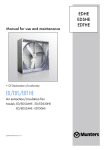
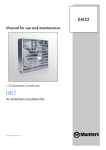
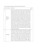
2 - USE EN CHARACTERISTICS ENGINE Engine Type OM 934 (EU Stage IV) (Mercedes-Benz) Fuel Diesel Number of cylinders 4 Injection system - Firing orde 1-3-4-2 3 liters - cm 5,1 - 5100 Bore mm - in 110 - 4.33 Stroke mm - in Displacement 135 - 5.31 Turbocharging System Turbocharging with charge air cooling (air/air) Turbocharger 2-TC dual stage charging with fixed geometry and waste-gate Compression ratio 17,6 Nominal rate rpm Idle rate Max operating speed 2200 - rpm 2500 Rated Power 231 CV-170 kW @ 2200 rpm Maximum torque 900 Nm @ 1200 - 1600 rpm Main Coupling type SAE3 Additional service PTO (type, max torque) - Exhaust Gas Aftertreatment SCR system, exhaust muffler with catalyst, AdBlue injection with supplying and metering unit 24 V - 100 A Alternator Cooling system Water cooling Cooling water cicuit Hydraulic Oil cooling Fan drive system Electric/Hydraulic/Mec. Motor type Hydraulic Blower fan speed rpm Number of blades Diameter 2300 14 mm - in 680 - 26.77 TRANSMISSION Transmission unit Type Gearshift hydrostatic, variable displacement pump and motor (Rexroth) liters - cm3 "Model 319 CVT - Continuous Variable Transmission" (Dana) Brakes Type Disc in oil bath on front and rear axle Foot brake Acts on the front and rear wheels Hand brake Hydraulic with negative action on the front axle Front axle Type Steering final drives (Dana) Brakes type - Limited slip system - Final drives Epicyclic Rear axle Type Steering with final drives(Dana) Brakes type - Limited slip system - Final drives Epicyclic 2-3 EN Suspensions Type Floating rear axle with automatic hydraulic lock Standard Front & Rear tyres Dimensions Pressure 17,5 R 25 22PR EM 60 TL (Mitas) bar - psi 7 - 102 Optional Front & Rear tyres Dimensions Pressure bar - psi - ELECTRICAL CIRCUIT Electrical circuit Ground Negative Battery standard 2x12V - 120Ah - 850A rif. EN Battery optional 2x12V - 180Ah - 1200A rif. EN Voltage regulator Built into the alternator HYDRAULIC CIRCUIT Hydrostatic pump Pump Type Displacement max Flow rate @ 2200 rpm Pressure A4VG145 - Axial piston variable pump (Rexroth) liters - cm3 l/min 0.1453 - 145.3 313 bar - psi 500 - 7251.88 liters - cm3 0.0935 - 93.5 Hydraulic circuit main pump Pump Type Displacement Flow rate @2200 rpm Pressure A11VO95 - Axial piston variable pump (Rexroth) l/min 210 bar - psi 350 - 5076.32 Hydraulic circuit secondary pump Pump Type Displacement Flow rate @ 2200 rpm Pressure PLP20.16 (Casappa) 3 liters - cm l/min 0.0169 - 16.9 36 bar - psi 250 - 3625.94 Main electrovalves Type Lifting circuit Extension circuit Tilting circuit Stabilizers Optional circuit Winch PVG100/6 (Rexroth) bar - psi l/min bar - psi l/min bar - psi l/min bar - psi l/min bar - psi l/min bar - psi l/min 350 (5076.32) 180 210 - 3045.79 180 280 (4061.05) 150 220 (3190.83) 265 (3843.5) 150 265 (3843.5) 180 Steering circuit Pump Type Displacement Flow rate @ xxxx rpm Pressure Load sensing 3 liters - cm l/min bar - psi Type 0.034 - 34 115 270 - 3916.01 Load-sensing Brake circuit Type Pressure Servo-assisted by hydrostatic drive bar - psi 175 - 2538.16 2-4 EN NOISE AND VIBRATION Acustic pressure level in the driver's cab LpA (according to NF EN 12053) Noise pressure level ensured in the LwA environment (according to directive 2000/14/EC modified by directive 2005/88/EC) The average weighted acceleration transmitted to the driver's hand/arm system (as per ISO 5349-2) dB(A) 80 (cab closed) dB(A) 108 (guaranteed) m/s2 < 2,5 HYDRAULIC MOTIONS SPEEDS Unladen lifting s Laden lifting s Unladen lowering s Laden lowering s Unladen extending s Laden extending s Unladen retracting s Laden retracting s Reverse tilt time unladen s Forward tilt time unladen s SPECIFICATIONS AND WEIGHTS Speed of movement for telehandler in standard configuration on flat ground (except particular conditions) Driving Speed Maximum speed km/h - mph 40 - 24.85 Forward unloaded km/h - mph 40 - 24.85 With nominal load km/h - mph - Reverse unloaded km/h - mph 40 - 24.85 With nominal load km/h - mph - Lifting Capacity Standard lifting height Lifting heigt at max capacity m - ft mm - in Forward reach at max capacity mm - in Max rated capacity with STD carriage and kg - lb forks Distance from center of gravity mm - in Capacity at max height with STD carriage kg - lb and forks Capacity at max reach with STD carriage kg - lb and forks Weight distribution with STD carriage and forks Truck weight with STD carriage and forks kg (unloaded) Front axle unloaded kg 31.6 - 103.67 13660 - 537.79 5500 - 12125.41 600 - 23.62 2500 - 5511.55 200 - 440.92 23986 - 52880.02 11328 - 24973.94 Rear axle unloaded kg 12658 - 27906.08 Max load per tyre unloaded kg 6329 - 13953.04 Drawbar pull Tractive force (Drawbar pull) Break out force with bucket (according to standard ISO 8313) Gradeability daN 10500 / Unloaded % 39 Loaded % 10 2-5 EN Turret Slewing turret 360° Locking system type Hydraulic system Outriggers Type Telescopic 3 elements Nb 4 Control Individual or simultaneous control LIQUID CAPACITIES Tanks capacities Hydraulic and Transmission Oil Liters 297 Fuel Liters 361 Diesel Exaust System (DEF) Liters 63 2-6 EN DIMENSIONS AND LOAD CHARTS MRT 3255 Plus Privilege Tier 4 in 47,24 5,12 40,47 2,36 15,08 319,45 331,18 258,58 55,47 147,64 55,47 16,97 16,54 118,19 126,18 130,16 149,72 20,43 81,26 98,39 255,51 279,53 13,78 C1 E1 E A F D J1 G K1 C B V 14° 20° 20° 218,90 184,65 234,06 255,51 193,31 275,59 36,73 12° 105° P 5560 4690 5945 6490 4910 7000 933 J H1 I K H2 mm 1200 130 1028 60 383 8114 8412 6568 1409 3750 1409 431 420 3002 3205 3306 3803 519 2064 2499 6490 7100 350 A3 ZY A A1 A2 A3 B C C1 D E F G H1* H2* I* J* J1* K K1 L M N O P* P2 P3 P4 Q R S1 S2 T U V Y Z L M *: ± 78 mm. Valore a metà corsa delle sospensioni. N O A1 A2 Worth one-half throw of the suspension. R T Q U S 2-7 EN Load chart Operating Mode: ON STABILISERS WITH FORKS CARRIAGE 2-8 EN Load chart Operating Mode: ON WHEELS (FRONT TURRET) 2-9 EN Load chart Operating Mode: ON WHEELS (TURRET ROTATED) 2-10 EN MONITORING AND CONTROL INSTRUMENTS 38 34 34 34 35 14A 35 32 35 28 8 6 33 14 13 4 35 8 3 12 15 17 21 35 37 18 19 9 10 20 11 23 23 22 1 25 5 26 27 29 2-11 EN DESCRIPTION 1-OPERATOR SEAT 2-13 2 - SAFETY BELT 2-14 3 - SWITCHES 2-15 4 – CONTROL PANEL and LOAD LIMITER “HMI” 2-36 5 - DIAGNOSIS SOCKETS 2-53 6 - SERVICE BRAKES PEDAL 2-53 7 - ACCELERATOR PEDAL 2-53 8 - FORWARD/NEUTRAL/ REVERSING MOVEMENT SELECTOR 9 - STEERING WHEEL ADJUSTER LEVER 2-54 2-55 10 - CONTROL LEVER FOR LIFTING LH ARMREST OF SEAT 2-55 11 - PROPORTIONAL ELECTROHYDRAULIC SERVO-CONTROLS 2-56 12 - OPTIONAL EXCLUSION CONTROL SWITCH 2-57 13 - SELECTOR FOR MOVEMENTS 2-57 OF ACCESSORIES AND PLATFORMS 2-57 14 - ROTATION BLOCKING PIN CONTROL LEVER 2-58 15 - SWITCHING ON AND REGULATING HEATING 2-59 16 - WINDSCREEN-WIPER LIQUID TANK 2-60 17 - CEILING LIGHT 2-60 18 - REAR WINDOW 2-60 OPENING LEVER 2-60 19 – DOOR CLOSURE 2-61 20 - ELECTRIC WINDOWS 2-61 21 - AIR DIFFUSERS FOR DEMISTING WINDSCREEN 2-62 22 - AIR DIFFUSERS OF HEATING 2-62 23 - BOOM SAFETY WEDGE 2-63 Recommendations Whatever the operator’s experience in this sector, he must be familiar with the location and function of all the instruments onboard and the controls, before starting operation of the forklift truck. All the instruments onboard must be checked immediately after start-up with the engine hot and at regular intervals during use, to immediately detect anomalies and solve problems without delay. If the instrument does not give correct indications, switch the engine off and immediately take the measures necessary to restore correct working. Ignoring these recommendations while using the forklift truck can have dangerous consequences. 2-12 EN 1-OPERATOR SEAT (1) Adjusting seat forwards-backwards using the control joysticks. Pull lever A (FIG.1) upwards. Move the seat forwards or backwards, as required, according to the arm-rests. Release the lever and make sure it returns to the blocking position. Adjusting the seat forwards-backwards Pull lever B upwards (FIG. 1). Position the seat as required. Release the lever and make sure it returns to the blocking position. (OPTIONAL) : The seat can also be moved forwards-backwards electrically by pressing the two buttons on the LH manipulator. It can also be inclined upwards forwards by 13°. Adjusting the seat height Pull lever C upwards (FIG. 1). Position the seat at the required height. Release the lever and make sure it returns to the blocking position. Adjusting the backrest inclination Pull lever D (FIG.1) upwards and incline the seat as required. Release the lever and make sure it returns to the blocking position. Adjusting the seat suspension according to weight The movement of the seat suspension may vary according to the operator’s weight. To carry out this operation, use knob E (FIG. 1) to select the required value. Lumbar adjustment of seat back-rest Turn knob “F” to adjust the lumbar area of the backrest. 1 F C A D E 13° 2-13 ) B EN 2 - SAFETY BELT (2) Sit correctly on the seat. - Check to make sure the seat belt is not twisted. - Wear the belt at the hip. - Fasten the safety belt and check to make sure it is locked properly. - Adjust the belt according to your body, avoid pressing against the hip and avoid excessive play. The telescopic lift must not be used if the seat belt is defective (Fixing, lock, seams, tears, etc.). Repair or change the seat belt immediately. 2 2 2-14 EN 3 - SWITCHES RH area overview (3) A - Emergency pump switch B - Radio control switch C - Suspensions on/off switch D - Machine suspensions halfway switch E - Machine completely raised/lowered selector switch F - Levelling control lever G - Parking brake switch H - Cruise control switch I - LH front stabilizer selector J - RH front stabilizer selector K - LH rear stabilizer selector L - RH rear stabilizer selector M - Stabilizers movement selector N - Stabilizers movements control O - Hydraulic pivot switch P - Steering type selector switch Q - Switch for resetting movement block R - Key selector for exclusion of Safety system S - Telehandler/platform selector switch key (only with platform) T - Pushbutton for restoring electric power supply from battery and allowing I.C. engine restart (only with platform) 3 A B D E C 53004849 F O P Q S R 3427 5300 933345 933345 2-15 I J N K L M T 65 9347 933345 H 934767 G EN A - EMERGENCY PUMP SWITCH (ONLY WITH PLATFORM) Switch, two-positions (1, 2,3.1): - when (1,3.1) is pressed, the safety motor pump is disabled - when (2,3.1) is pressed, the safety motor pump is enabled. For more information regarding the control see “Platform User Manual.” (3.1) B -RADIO-CONTROL SWITCH Switch (B,3.1), two-positions (1, 2,3.1): - press on (1,3.1) the radio control is disenabled; - press on (2,3.1) the radio control is enabled. When the radio-control is active, a green indicator lights up in the control panel (1,3.1a) and a led (B1,3.1) on the switch (B,3.1) lights up. When the radio control is enabledby means of the switch (B,3.1), the machine switches off, for safety. 3.1a 3.1 1 1 3 B1 1 2 2 A B 2-16 EN LEVELLING AND SUSPENSIONS CONTROL LEVELLING/SUSPENSIONS DEVICE The forklift truck is provided with hydropneumatic suspensions with electronic corrector for levelling with respect to the ground. The axles are connected to the structure by means of four hydraulic jacks and suspensions which can be controlled by the operator, from the driving seat, depending on the use. The suspensions and levelling are meant for: - absorbing the shocks when the vehicle is running. - levelling the vehicle with respect to the ground The suspensions only work if the boom is retracted completely and the turret rotation blocking pivot is activated. With active, controls the the are suspensions manipulator disenabled. Before using the suspensions, level the vehicle frame so that it is parallel to the ground. SUSPENSIONS CONTROLS C - SUSPENSIONS ON/OFF SWITCH Press switch (C,3.2) to activate/deactivate the vehicle’s suspensions (ON, OFF,3.2) When the suspensions are active, a green indicator lights up in the control panel (1,3.2a) and a led (2,3.2) on the switch lights up (C,3.2). The machine manual levelling lever (F,3) does not work. 3.2a 3.2 OFF 2 ON C 2-17 1 EN D - SUSPENSIONS IN WORK SITE SETUP Keep pushbutton (D,3.3) pressed for a few seconds to activate the configurations of the suspensions in “work site setup”. A led on switch (1,3.3) lights up. There are two configurations in “work site setup”: 1. suspensions halfway and vehicle frame parallel to the ground and a green indicator light (1,3.3a) on the control panel lights up. 2. suspensions completely lowered and machine frame parallel to the ground and a green indicator light (2,3.3a) on the control panel lights up. In cyclic mode, press and re-press pushbutton (D,3.3), to select the required machine setup (suspensions halfway or completely lowered). E - SUSPENSIONS SETUP CONTROL Press pushbutton (E,3.3)to change the suspensions setup, raised or lowered, determining the vehicle’s height off the ground. The suspensions travel is 156 mm. The pushbutton has 3 positions: 1. increases the height from the ground (+156 mm) and a green indicator light “1” on the control panel lights up (3.3b) 2. neutral (3.3) 3. decreases the height from the ground (- 156 mm) and a green indicator light (2,3.3b) on the control panel lights up. Press pushbutton (D,3.3) to reset the suspensions and the levelling of the vehicle frame. 3.3b 3.1d 3.3a 3.3 E 1 2 1 1 2 0 2 D 2-18 1 EN LEVELLING CONTROL F - LEVELLING LEVER Lever (F,3.4) controls the vehicle levelling transversely (+8° and -8°) and longitudinally (+3° and -3°). The lever moves in 4 directions and inclines the vehicle: - forward-backward (longitudinal inclination) (3.4) - RH-LH (transverse inclination) (3.4) To make the vehicle perfectly horizontal, check the level gauge: - green bubble machine leveled (1,3.4a). - red bubble machine is not leveled (2,3.4a). Adjust the vehicle’s slope longitudinally only if necessary, moving the truck at slow speed trough short distances. The truck’s stability is at risk. To check the vehicle’s stability, use the spirit level (1,3.4a). The levelling operation is not possible when: - the telescopic boom is lifted, more than 30° off the ground, - the turret is rotated by more than 15°. 3.4 F 3° 8° 53004849 8° 3° 3.4a 1 2 2-19 EN G - PARKING BRAKE SWITCH Two-position (1, 2,3.5) switch (G,3.5) with safety block (3,3.5). The parking brake acts on the front axle. - To release the brake, push the button in position (1,3.5). - To apply the brake, push the button in position (2,3.5) and a red indicator light (1,3.5b) on the control panel lights up. To release the brake from (2,3.5) to (1,3.5), while pressing the switch, act on the safety lock (3,3.5). , - e a a a H - CRUISE CONTROL SWITCH The machine is equiped with the cruise control system. - The switch (G,3.5) identifies the control to set the cruise control system. The system automatically accelerates or decelerates the machine to maintain a pre-set speed. The system takes over the throttle of the machine to maintain a steady speed as set by the driver. - - Set the speed The driver can choose to increase or decrease the speed of the machine by pressing the accelerator pedal and then set the desired speed by pressing the switch (G,3.5). The green indicator lights up on the control panel (1,3.5a). On the switch (G,3.5) the led lights on (1,3.5) to indicate that the function is active. - i o i The system deactivates in event of: - service brake pressure or parking brake activated, - pressure switch (G,3.5), - forward/neutral/reversing movement selector in neutral position, - every motions of the telescopic boom, - every machine alarms. 3.5b 3.5 3.5a 1 1 1 3 H1 2 G H 2-20 EN STABILIZERS CONTROLS I: SELECTS THE FRONT LEFT OUTRIGGER. J: SELECTS THE FRONT RIGHT OUTRIGGER. K: SELECTS THE REAR LEFT OUTRIGGER. L: SELECTS THE REAR RIGHT OUTRIGGER. On the switch (I, J, K, L,3.5) the led lights on (1,3.5) to indicate that the function is active. M - OUTRIGGER UP-DOWN/ EXTENSION-RETRACTION SELECTOR Once the outrigger/s has/have been selected, this selector can be used to extend or retract or lower and lift the stabilizers. - Position M1: the outriggers lift or lower (M2,3.5) - Position M2: the outriggers extend or retract (M2,3.5). Consult the next paragraph when carrying out the required operations. N - OUTRIGGER UP/DOWN EXTENSIONRETRACTION CONTROL After selecting one or more stabilizers, and the stabilizers movements using selector (M,3.5), use pushbutton (N,3.5) to control the movements of the stabilizers. For extension of the stabilizers selector (M,3.5) must be set in position (M2,3.5), press pushbutton (N,3.5) in position (N1,3.5). To retract the stabilizers, press pushbutton (N,3.5) to position (N2,3.5). To lower the stabilizers, after having positioned selector (M,3.5) at (M1,3.5) press pushbutton (N,3.5) to position (N1,3.5). To raise the stabilizers, press pushbutton (N,3.5) to position (N2,3.5). 3.5 I1 N1 J1 N2 I J M1 K1 L1 M2 K L 2-21 EN I - TURRET ROTATION BLOCK PIVOT CONTROL With the turret centred, press the pushbutton to insert (1,3.6) or to extract (2,3.6) the pivot. - Press the pushbutton on (O1,3.6) to extract the pivot, - Press the pushbutton on (O2,3.6) to insert the pivot The rotation block pivot is not activated if the turret is not centred perfectly. Observe the three indicator lights on the control panel to check the following: 1. 2. 3. 4. indicator light Off, the turret is rotated and the rotation block pivot is deactivated, green indicator light On, turret aligned to the truck and turret rotation pin is deactivated (1,3.6a), yellow indicator light On, turret almost aligned with the truck and the turret rotation pivot is deactivated (2,3.6a), green indicator light On, turret aligned to the truck and turret rotation pin is activated (3,3.6a). Turret rotation blocked. H - STEERING TYPES SELECTOR Three types of steering. To select the three possible types of steering, press the switch as follows: - front and rear steering wheels (P1,3.6b), - front steering wheels (P2,3.6b), - wheels in oblique position (crab steering) (P3,3.6b). On the control panel there are three indicators which light up with a green light (P1, P2, P3,3.6b) depending on the steering selected. Before selecting a type of steering, check the alignment of the rear and front wheels. 3.6b 3.6a 3.6 1 O1 P1 P1 P2 P2 P3 P3 O2 2-22 3 2 EN Q - SWITCH FOR RESETTING MOVEMENT SAFETY SYSTEM The truck with turret rotated, with the boom extended and/or raised above 3m, does not move. It can be made to move only in exceptional cases and for safety reasons by pressing switch (Q,3.7). The switch (Q,3.7) has two-positions (1, 2,3.7) and with safety block (2,3.7). - To authorize movement, the operator must turn switch (Q,3.7) to position (1,3.7) and a red indicator lights up on the control panel (1,3.7a). - To reset the movement Safety system, the operator must turn switch (Q,3.7) to position (0,3.7). To avoid affecting the stability of the truck, move slowly for short distances on flat, level ground. The operator and the truck are exposed to risks. 3.7a 3.7 0 2 Q Q 1 2-23 EN TELEHANDLER/PLATFORM SELECTOR SWITCH KEY (only with platform) - Handling or platform operation from driver’s cab controls (1a,3.8). - Platform operation from control console (1b,3.8). (For more details: Baskets use manual) PUSHBUTTON FOR RESTORING ELECTRIC POWER SUPPLY FROM BATTERY AND ALLOWING I.C. ENGINE RESTART (only with platform) If the “emergency stop” button is pressed from the basket, the supply of electricity from the battery is cut off and the I.C. engine switches off. Keep button pressed (2,3.8) to restore supply of electric current to the battery and make it possible to restart the i.c. engine (For more details: Baskets use manual) 3.8 1b 1a 1 2 2-24 EN KEY SELECTOR FOR EXCLUSION OF SAFETY SYSTEM The Manitou telehandler is equipped with an electronic safety system which controls the overload of the macine in the operating phase. The system acts automatically to block the boom movements. It is only in exceptional cases and for reasons of safety, that the system can be deactivated manually. With the safety system deactivated, the operator and the forklift truck are exposed to risks and there is nothing to prevent overload and/or overturning of the vehicle. Key selector To disable the Safety System, the operator must turn (1.1,3.9), a key selector in the cab. Key (1.2,3.9a) is kept inside a safety box (1.3,3.9a) placed to RH side of the driver’s (3.9). Key selector (1.1,3.9) has two positions: - safety system is activated (1,3.9); - safety system is deactivated (0,3.9). During normal use, the key selector is turned to position (1,3.9), so the safety system is activated. 3.9a 3.9 1.3 1 0 1.2 1.1 1.2 2-25 EN In case of emergency, if the safety system is to be deactivated, the operator must: - take hammer (1.4,3.9b) on the side of the safety box (1.3,3.9b); - break the glass (1.5,3.9b) on safety box (1.3,3.9b); - take key (1.2,3.9b) and insert it in key selector (1.1,3.9b); - turn key selector (1.1,3.9b) inposition (0,3.9b) to deactivate the safety system. Rotate key selector (1.1,3.9b) in position (0,3.9b) to proceed and continue with the emergency manoeuvres, making movements opposite to those which can lead to instability and/or overloading of the machine. Note: When the safety system is disenabled, enable it automatically: - a red warning light (1.7,3.9c), - an alarm sound, - an visual indicator (steady red light above cab) (1.6,3.9c), - to warn the driver and other persons who may be present outside the vehicle of a possible danger situation. With disenabled safety system all the movements of the machine are restricted to 15% of their maximum speed. When the emergency procedure is complete, the key must be replaced inside the safety box and the glass cover must be replaced. 3.9b 3.9c 1.7 1.3 1.5 1.2 1.4 1.6 1 0 1.2 1.1 2-26 EN LH area switches (3.16) NOTE: The location of the switches may vary depending on the options. ò FRONT WINDSHIELD WIPER AND WINDOW WASHER SWITCH The switch (1,3.10) has three position (0, 1a, 1b,3.10). This switch (1,3.10) identifies the control which activates the front wiper (1a,3.10) and dispenses washing fluid (1b,3.10), initiating a sweeping motion and fluid spray to clear the windshield. When the front wiper is actives lights up the LED (2,3.10) on the switch (1,3.10). To deactivate the window washer, just release the switch. , l EMERGENCY STOP” BUTTON In case of emergency, press the mushroomshaped red button (1,3.11) to stop the I.C. engine of the telehandler. On the control panel the indicator light indicates the active function (e paragraph: “Instruments control panel”). e i e i . l i Warning: hydraulic movements suddenly stop when using this button. If possible, stop the telehandler before using the emergency stop. Turn the button (1,3.11) to disable it and to restart the telehandler. - WINDOW LIFT (POWER-OPERATED) SWITCH This switch (1,3.12) active the control that raises or lowers the cab door window using a powered mechanism. Opening the window Press the switch forward (1a,3.12) and hold it until the window has moved to the desired position. Press the switch forward (1a,3.12) and hold it until the window will open all the way. Closing the window Press the switch back (1b,3.12) and hold it until the window has moved to the desired position. Press the switch back (1b,3.12) and hold it until the window will close all the way. - o o o e e 3.11 3.12 3.10 1a 1b 0 2 1a 1 1b 2-27 1 EN Under roof area switches (3.13) NOTE: The location of the switches may vary depending on the options. ò ROTATING BEACON LIGHT SWITCH This switch (1,3.14) controls the operation of the rotating beacon light. On the switch (1,3.14) the led comes on (2,3.14) to indicate that the function is active. l è o NOTE: Except in case of emergency, it is advised to disable the rotating beacon light when the ignition is switched off to avoid a flat battery. CABIN ROOF WIPER AND WASHER SWITCH This switch (1,3.15) sprays a cleaning liquid on the cab roof and uses the wiper to clear the liquid from the cab roof. The switch (1,3.15) has three positions: - deactivated (0,3.15); - for window wiper (1a,3.15); - for window washer (1b,3.15). To deactivate the window washer, just release the switch (1b,3.15). On the switch (1,3.15) the led comes on (2,3.15) to indicate that the function is active. n o . i REAR WINDOW WASHER AND WIPER SWITCH The switch (1,3.16) has three position (0, 1a, 1b,3.16). This switch (1,3.16) identifies the control which activates the rear wiper (1a,3.16) and dispenses washing fluid (1b,3.16), initiating a sweeping motion and fluid spray to clear the windshield. When the rear wiper is actives lights up the LED (2,3.16) on the switch (1,3.16). To deactivate the window washer, just release the switch. l o - e 3.13 3.15 3.14 3.16 0 0 2 2 2 1a 1a 1 1 1 1b 2-28 1b EN Armrests switches (3.17) OPTIONAL EXCLUSION CONTROL SWITCH This switch (1,3.18) enables or disables the command roller of the “optional” (example: rope ascent/descent) on LH joystick (1,3.17). The attachment can be used only after enabling the optional. When the function is activated lights up a black indicator on the control panel and the LED (2,3.18) on switch (1,3.18). “ABC” SELECTOR FOR MOVEMENTS OF ACCESSORIES AND PLATFORMS This selector (1,3.19) is located on the LH armrest of the driver’s seat and select the hydraulic movements of an accessory that will be controlled by roller “optional” on the LH joystick (1,3.17). When the selector (1,3.19) is in position (A,3.19) the roller “optional” on LH joystick controls a possible hydraulic movement of an accessory. If the accessory has more than one hydraulic movement press the selector in position (B,3.19) or (C,3.19). 3.18 1 3.17 3.19 1 2 1 2-29 EN OPTIONAL FUNCTIONS SWITCHES RADIO-CONTROL SWITCH (,paragraph “Switches” ,3.1) ELECTRIC ACCELERATOR SWITCH The function of the switch (1,3.20) is to increase or decrease the I.C. engine rpm electrically. - The switch has two positions: - pressing on (1a,3.20) will cause I.C. engine rpm to accelerate gradually, - deactived (1c,3.20), - pressing on (1b,3.20) will cause I.C. engine rpm to decelerate gradually. ENGINE BRAKE SWITCH The engine brake decelerates the telehandler without using mechanical friction in order to avoid the overheating of the brake system. This brake is mainly used in the long descents, and it allows to brake the machine without stressing the brakes. Press switch (2,3.21) to enable or disable the engine brake. On the control panel the red indicator light indicates that the function is active ( paragraph: “Instruments and control panel”). On the switch (2,3.21) the led comes on (1,3.21) to indicate that the function is active. When activating the engine brake is excluded the inching function ( paragraph: “Service brake pedal”). The engine brake is controlled by pressing the brake pedal of service and allows two stages of deceleration, a low and an intense depending on the stroke of the pedal. When starting the engine is always activated the inching function. 3.20 3.21 1a 1 1c 1 2 1b 2-30 EN STABILIZERS AUTOMATIC LEVELLING PUSHBUTTON The machine is provided with a device for levelling the outriggers in relation to the ground to be able to level the machine and therefore lift the boom to the maximum height in complete safety and stability. Working of the device Before levelling the machine select the four outriggers by means of switches (I, J, K, L, 3.5). Keep button (2, 3.22) pressed until the machine is leveled and stabilized. On the control panel, in “Stabilty page” check the indications of machine leveled (2, 3.22a) and stabilized (1, 3.22a). AUTOMATIC STABILIZATION PUSHBUTTON The machine is provided with a device movements of automatic stabilizers in relation to the ground to be able to stabilize the machine and therefore lift the boom to the maximum height in complete safety and stability. Working of the device Before to stabilize the machine select the four stabilizers by means of switches (I, J, K, L, 3.5). Keep pressed the button (1, 3.23) to activate the automatic movements of stabilizers: - extension and descent (1a, 3.23), - retraction and ascent (1b, 3.23), and until the machine is stabilized. On the control panel, in “Stabilty page” check the indications of machine stabilized (1, 3.23a). 3.22 3.22a 3.23 1 1 2a 1 2 2 2b 2-31 EN HYDRAULIC ACCESSORY BLOCK BUTTON Precautions to be taken if the machine is provided with the “hydraulic accessory block” device. This hydraulic device with electric control makes it possible for the operator to block/release an accessory from the driving seat. The devices activates two pins (X, Y,3.24) which move horizontally on the quickrelease coupling, outwards (blocking the accessory) and inwards (releasing the accessory). To block the accessory, the two check pins must come completely out of the quick-release coupling (3.25) Description of the controls To select the “hydraulic accessory block” device, the operator must keep pressed the pushbutton on the switchboard (1,3.25). The pushbutton has two positions: pressed on (1a,3.25), the “hydraulic accessory block” is activated: pressed down (1b,3.25), the “hydraulic accessory block” is deactivated. By keeping the pushbutton pressed (1b,3.25) the operator can activate the two pins “(X, Y,3.24) pressing the optional rocker button (4,3.25) on the LH manipulator (3,3.25): - to the RH, the two pins come out and block the accessory; - to the LH, the two pins retract and release the accessory. By releasing the pushbutton (1a,3.25) the operator deactivates the hydraulic accessories block and restores the standard optional controls. If the equipped fitted is provided with hydraulic connections, connect these in the quick-release coupling on the boom, carrying out the operation with the IC engine switched off ( Chapter: 4 - OPTIONAL ATTACHMENTS FOR USE WITH THE RANGE). 3.24 X Y 3.25 1a 4 2 1 X Y 1b 2-32 3 EN BOOM SUSPENSION SWITCH The boom is suspended to reduce shaking of the telehandler on rough ground (e.g. moving straw in a field). The switch (2,3.26) has two position. On the switch (2,3.26) the led comes on (1,3.26) to indicate that the function is active. On the control panel a green indicator light up (1,3.26) to indicate that function is active ( paragraph: “Instruments and control panel”). Operation: - set the forks or attachment on the ground and relieve the front wheels a few centimetres only. - press switch set to position (2a,3.26), the visual indicator comes on indicating that boom suspension is activated. - press switch set to position (2b,3.26), the visual indicator goes out indicating that boom suspension is deactivated. Boom suspension is active to a lifting height of 3 m from the axis of articulation of the carriage with respect to the ground with the boom retracted. When you move beyond this height or make another hydraulic movement (tilting, telescoping, attachment), boom suspension is momentarily deactivated and the visual indicator of switch 1 goes out. - When the I.C. engine is off, boom suspension is automatically deactivated. 3.26 2b 1 2 2a 2-33 EN CAB FRONT WORK LIGHTS SWITCH This switch (2,3.27) controls the operation of the front work lights. - On the switch (2,3.27) the led comes on (1,3.27) to indicate that the function is active. CAB REAR WORK LIGHTS SWITCH This switch (2,3.28) controls the operation of the rear work lights. On the switch (2,3.28) the led comes on (1,3.28) to indicate that the function is active. BOOM HEAD WORK LIGHTS SWITCH This switch (2,3.29), controls the operation of the boom head work lights. - On the switch (2,3.29) the led comes on (1,3.29) to indicate that the function is active. 3.27 1 3.29 3.28 1 1 2 2 2 2-34 EN REAR WINDOW DEMISTING AND DEFROSTING SWITCH This switch (2,3.30) active the control that distributes a low electrical current to the rear window to aid in removing frost, fog and mist. On the switch (2,3.30) the led comes on (1,3.31) to indicate that the function is active. AIR CONDITIONING ON-OFF SWITCH This switch (2,3.31) identifies the control that operates the air conditioning unit. On the switch (2,3.31) the led light up (1,3.31) to indicate that the function is active. AIR CONDITIONING VENTILATION CONTROL This switch (2,3.32) identifies the control which activates the fan and circulates air at a speed selected by the user. The switch has three positions: - minimum ventilation (2a,3.32), - medium ventilation (2b,3.32), - maximum ventilation (2c,3.32). On the switch (2,3.32) the led light up (1,3.32) to indicate that the function is active. MULTI-PURPOSE BUCKET CONTROL SWITCH This switch (2,3.33) identifies the control for operation of the multi-purpose bucket. On the switch (2,3.33) the led light up (1,3.33) to indicate that the function is active. 3.30 3.32 3.31 3.33 2a 1 1 1 2b 1 2 2 2c 2 2-35 2 EN 4 – CONTROL PANEL and LOAD LIMITER “HMI” The control panel (1,4) with colour screen 9” display shows and informs the operator of all the steps of the working of the telehandler. Eight control modes are saved in memory of the HMI panel (4.3) and these can be selected by machine-human interface keypad (2,4) on the armrest (3,4) in cabin. 4 1 2 3 2-36 EN CONTROL PANEL PAGES - Splash screen (4.1) - Menu page (4.2): t Driving page (F1,4.3) t Working page (F2,4.3) t Geometric limits page (F3,4.3) t Maximum speed of hydraulic movements page (F4,4.3) t Alarms page (F5,4.3) t Stability page (F6,4.3) t Setting page (F7,4.3) 4.2 4.1 F6 F1 F2 F4 F5 F7 4.3 F1 F2 F3 F4 F6 F5 F7 2-37 n e i . i - e l a O - - - - a EN MACHINE DISPLAY CONTROLLER Keypad with encoder (1,4.4) This instrument (1,4.4) provide excellent tactile feedback to the user and the greatest advantage of encoder is increase the functions in one control. Put display functions within reach - 5 hot keys for rapid navigation - scroll with rotary encoder knob - Select with pushbutton Functions: - Rotary encoder knob with select pushbutton (2,4.4): turn the knob to scroll the pages and to navigation into pages (if possible) after press it to select or confirm the choice. - LOAD CHART key (2b,4.4) press it to enter in “ F2 - Load limiter page”, - HOME key (2c,4.4)::push it to enter in “Machine diagnostic mode control”, - BACK key (2d,4.4): press it to back in the choice, - MENU key (2e,4.4): press it to enter in “Menu screen”, - OPTIONAL key (2f,4.4): from “F1 - Driving page” press it to enter in the “Driving setup page”. 4.4 2e 2f 2b 2a 2c 2d 2-38 EN Control modes saved in memory F1 - DRIVING PAGE 1. Engine coolant temperature gauge indicator (1,4.5) 2. The indicator warning lights up when (2,4.5): t the engine coolant is overheating t or low liquid level 3. Fuel level indicator (3,4.5) 4. The indicator lamp lights up (4,4.5) when the fuel level in the tank is lower than 10% of its capacity 5. Rev counter (x100 rpm) (5,4.5) 6. Partial (p) and total (t) hour-counter (6,4.5) 6.1. Time(t) and date (d) (6a,4.5) 7. Speedometer (km/h or mph) (7,4.5) 8. Moving direction indicator (8,4.5): t N= neutral t F= forwards t R= reverse 9. Warning and indicator lamps (9,4.5) Symbol overview: position lights low beams high beams direction lights rear axle lock front wheels alignment rear wheels alignment front wheel steering concentric wheel steering 4.5 9 9 9 9 9 9 2 5 10 7 1 3 4 8 6 6a 9 9 11 13 2-39 12 9 EN crab steering telescopic boom hydraulic movements control green indicator light On, turret aligned to the truck and turret rotation pin is deactivated yellow indicator light on, turret almost aligned with the truck and the turret rotation pivot is deactivated green indicator light on, turret aligned to the truck and turret rotation pin is activated. Turret rotation blocked. resetting movement safety system suspensions suspensions completely lowered suspensions completely raised suspensions halfway handling and loader mode road travel mode eco fuel mode retarder (optional) telescopic boom suspension (optional) remote control (optional) I.C. engine severe fault I.C. engine malfunction alternator exicitation I.C. engine oil pressure I.C. engine oil level (0-100 %) (The red warning lamp lights on when the level is under at 20 %) engine intake air filter transmission oil filter parking brake telehandler door hydraulic oil filter hydraulic oil filter delivery is blocked or damaged 2-40 EN service (maintenance required) hydraulic oil filter exhaust is blocked or damaged hydraulic oil filters delivery and exhaust is blocked or damaged boom chains anomaly anomaly (according to standard EN 280:2001+ EN 280: 2001/ A1: 2004). diesel exhaust fluid (DEF) level indicator emissions-relevant malfunction of the exhaust gas aftertreatment system or DEF supply LIM Machine speed or torque operating restriction cruise control setting the maximum speed of the machine “emergency stop” red button safety system exclusion warning / alarm 10. Diesel exhaust fluid (DEF) level indicator that provides information about the quantity of DEF in the tank (10,4.5). 11. Machine alarm code: in normal operating conditions are displayed (11,4.5). 12. Machine warning code: in normal operating conditions are displayed (12,4.5) 13. Messages area and confirm of accessory (13,4.5). F1.1 - DRIVING SETUP PAGE From “F1 - Driving page” press the OPTIONAL key on keypad to enter in the “Driving setup page”: 14. Eco fuel mode ON-OFF (1,4.6a) 15. Drive mode select (2,4.6a): t road t forks 16. Setting the maximum speed of the machine (3,4.6a). 17. Overraide ON-OFF (4,4.6a). Rotate the knob encoder to choose the setting mode and press it to select the setting mode. Rotate the knob encoder to set the mode. Press the knob encoder to confirm the setting mode. 1 4.6a 4 2 3 2-41 EN F2 - WORKING PAGE 1. Load conditions The colored bar indicate the percentage of the load lifted referred to the operative condition of the machine: t Green reference (1a,4.6): safety area. t Yellow reference (1b,4.6): alarm area, load lifted 90% more than permitted load (external warning sound active) . t Red reference (1c,4.6): Block area, load lifted 100% more than permitted load (external warning sound active). 2. Messages area and confirm of accessory (2,4.6) 3. Machine alarm code: in normal operating conditions are displayed (3,4.6) 4. Machine warning code: in normal operating conditions are displayed (4,4.6) 5. Reading main operating data t Height off the ground (H) (reading in “Meters ”, with a decimal) (5,4.6) t Boom angle (A) (reading in “Degrees ”, with a decimal) (5,4.6) t Boom length (L) (reading in “Meters ”, with a decimal) (5,4.6) t Operating radius (R) Measurement of the distance from the fifth wheel centre to the projection of the point of applicaton of the load.(reading in “Meters ”, with a decimal) (5,4.6). t Weight of load lifted (LOAD) (reading in “Tons ”, with a decimal) (6,4.6). t Maximum permitted load (MAX) in the current configuration of the machine (7,4.6) (reading in “Tons ”, with a decimal). t Turret angle R (reading in “Degrees ”) (5,4.6). : metric unit [length unit (m) and weight unit (ton)] or imperial unit [length unit (ft) and weight unit (kLb)] 6. Geometric limits set (10,4.6) ( F3 - GEOMETRIC LIMITS PAGE ) 4.6 9 7 9 6 8 8.1 2EM 8.2 5 5 10 1 1 7.1 9 9 7 9 3 2-42 2 4 9 EN 7. 8. Slowing settings view (6,4.6) (For more details: next paragraph “Slowing page”). Dynamic load chart (7, 7.1,4.6). Forks example: 9. Working configuration - The first digit concerns the operating mode (8.1,4.6): t 1 = On Stabilisers t 2 = On wheels (front turret). t 3 = On wheels (turret rotated). t 4 = On stabilisers partially extended. - The second digit (8.2,4.6) concerns the equipment being used (PT,forks,etc...). 10. Function and alarm indicator lights (9,4.6) Symbols overview: I.C. engine severe fault I.C. engine malfunction telescopic boom suspension (optional) rear axle lock green indicator light On, turret aligned to the truck and turret rotation pin is deactivated yellow indicator light on, turret almost aligned with the truck and the turret rotation pivot is deactivated green indicator light on, turret aligned to the truck and turret rotation pin is activated. Turret rotation blocked. suspensions suspensions completely lowered suspensions completely raised suspensions halfway “emergency stop” red button safety system exclusion warning / alarm 2-43 EN F3 - GEOMETRIC LIMITS PAGE From “F2 - Working page” press the OPTIONAL key on keypad to enter in the “F3-GEOMETRIC LIMITS PAGE”: 1. Geometric limits Ranges from 1 to 5 indicate the programmed limit value. t t t t t With the icon switched on, the limit is exceeded and the movements are blocked. Indication appears when the limiter is programmed: Height limitation (1,4.7) Limitation to the RH (2,4.7) Limitation to the LH (3,4.7) Limitation clockwise direction of rotation (4,4.7) Limitation anticlockwise direction of rotation (5,4.7) Setting the work area limit - Stop the machine movements. - Display page “F3 - GEOMETRIC LIMITS PAGE”. - The operator must position the machine, turret and telescopic boom in the working position and restrict a limited area of action. - Now program each work area limit by using the keypad, rotating the knob to select the area limit and press the knob button to confirm and set the choice. - Press the BACK key on keypad to return in “F2 - Working page”. Make sure the display shows the selected limit values. If no value is displayed (for example. “0.0”) it means the limits are not set, or are disenabled. - To RESET one or more work area limits, keep the knob corresponding to the work limit pressed for a few seconds. For reasons of safety, even with the work area limit programs activated, check the machine dimensions during the work phases (4.7). 2. Reading main operating data. Current values (6,4.7) Working configuration (12,4.7) 3. 4.7 7 7 8 7 1 6 6 6 6 6 5 6 12 2EM 4 6 3 2 7 7 9 11 2-44 10 7 EN 4. 5. 6. 7. Messages area and confirm of accessory (11,4.7) Machine alarm code: in normal operating conditions are displayed (9,4.7) Machine warning code: in normal operating conditions are displayed (10,4.7) Function and alarm indicator lights (7,4.7) Symbols overview: I.C. engine severe fault I.C. engine malfunction telescopic boom suspension (optional) rear axle lock green indicator light On, turret aligned to the truck and turret rotation pin is deactivated yellow indicator light on, turret almost aligned with the truck and the turret rotation pivot is deactivated green indicator light on, turret aligned to the truck and turret rotation pin is activated. Turret rotation blocked. suspensions suspensions completely lowered suspensions completely raised suspensions halfway “emergency stop” red button safety system exclusion warning / alarm 2-45 EN F4 - SLOWING PAGE Is possible to save five systems to work: 1. t t t t t Slowing down (1,4.8): Maximum speed (100%) (1a,4.8) 1 Slowing down (1b,4.8) 2 Slowing down (1c,4.8) 3 Slowing down (1d,4.8) 4 Slowing down (1e,4.8) Is possible to set the maximum speed of hydraulic movements control: t maximum ascent speed of telescopic boom (2a,4.8) t maximum descent speed of telescopic boom (2b,4.8) t maximum extension speed of telescopic boom (2c,4.8) t maximum retraction speed of telescopic boom (2d,4.8) t maximum speed of inclination of load upwards (2e,4.8) t maximum speed of inclination of load downwards (2f,4.8) t maximum speed of attachment movements control: ascent, clockwise rotation, to the RH, upward inclination (depending on the attachment installed) (2g,4.8) t maximum speed of attachment movements control: descent, anticlockwise rotation, to the LH, downward inclination (depending on the attachment installed) (2h,4.8) The maximum speed of hydraulic movements control is expressed in percentage: from 0 to 100 % . To select a system to work Select the “F4 - Slowing page” (4.8) Rotate the knob encoder on keypad to select the “Slowing down” system work (1,4.8): t MAX (1a,4.8) t 1 (1b,4.8) t 2 (1c,4.8) t 3 (1d,4.8) t 4. (1e,4.8) Press knob encoder to confirm the “Slowing down” system work selected (4.8). Automatically will open the “Working page” (4.6). with “Slowing down” system work selected. 4.8 1 2 2 1a 1b 1c 1d 1e 6 3 5 2-46 4 6 EN To set and save the “2 Slowing down” system to work (example): - Rotate the knob encoder to scroll the “Slowing down” (1,4.8) - Press the knob encoder to select the “2 Slowing down” system work (1b,4.8a) and settings space are shown (4.8). - Rotate the knob encoder to choose the controls (2,4.8b) of: t saving (2a,4.8b) t setting (2b,4.8b) t deleting (2c,4.8) - Press the knob encoder to enter in the “setting” screen (3,4.8c). - Rotate the knob encoder to select the hydraulic movement to be set (3,4.8c). In correspondence of hydraulic movement a cursor lights up (3.1,4.8c). - Press the knob encoder to enter in percentage setup (3.1,4.8c). - Rotate the knob encoder to set the percentage (3.1,4.8c) of maximum speed of hydraulic movements control. - Press the knob encoder to confirm the percentage set (3.1,4.8c). - Repeat these steps for each hydraulic movement to be set (3.1,4.8). - Rotate the knob encoder to choose the controls (4,4.8d) of: t Saving (4,4.8d) - Press the knob encoder to save the settings (4,4.8d). To delete the “2 Slowing down” system to work from memory (example) Select the “F4 - Slowing page” (4.8) Rotate the knob encoder on keypad to select the “2 Slowing down” system work (1,4.8a), - Rotate the knob encoder to choose the controls (2,4.8b) of: t setting (2a,4.8b) - Press the knob encoder on “setting” (3b,4.8) to select the hydraulic movement to be delete. - Rotate and press the knob encoder on: t deleting, to delete the settings (1a,4.8) into “2 Slowing down” system work (1a,4.8). 4.8a 4.8b 2a 2b 1 2c 4.8c 3 4.8d 3 3.1 3 3 3 3 2-47 EN 2. Messages area and confirm of accessory (5,4.8) Machine alarm code: in normal operating conditions are displayed (3,4.8) Machine warning code: in normal operating conditions are displayed (4,4.8) Warning and alarm indicator lights (6,4.8) Symbol overview: 3. 4. 5. warning / alarm F5 - ALARMS PAGE The indicators with the red light on the central unit or the component indicate an error or an anomaly. In the event of a component failure, the system stops all the movement. 1. Colored bar indicate load conditions (8,4.9) 2. Engine units errors codes (9,4.9) 3. Warning list (1,4.9) Example: 123 [code warning] LMI_ TXTAL1 [description warning] 4. Alarm list (2,4.9) Example: 123 [code alarm] LMI_ TXTAL1 [description alarm] 5. Messages area (3,4.9) t Attention, alarm telehandler (4,4.9). t Telehandler alarms code (5,4.9). t Telehandler warnings code (6,4.9). t Red warning lights and indicator lights (7,4.9) Symbol overview: DISPLAY, display in cab IO-CORE, control unit to control the voltage MC2M unit on turret 4.9 7 8 7 7 1 2 7 7 9 4 5 3 2-48 6 4 EN MC2M unit on frame LMI load limiter control unit joystick turret rotation encoder LE70 unit suspensions acknowledgement of attachment radio remote controles (optional) extension outriggers boom encoder telescopic boom winder encoder pressure transducers distributor hydrostatic transmission alarm I.C. engine malfunctions I.C. engine stop service “emergency stop” red button safety system exclusion warning / alarm 2-49 EN F6 - STABILITY PAGE 1. Graduated electronic level gauge. Makes it possible to check the level (3,4.10) of inclination of the machine in the transverse and longitudinal direction. If necessary, adjust the machine inclination using the levelling and/ or stabilizers. 2. Stability and Resting area. During the working phase, it is possible to display the area on which the machine rests on the ground. The machine’s (1,4.10) resting surface depends on the operating mode selected (stabilizers, wheels, etc..). On the stabilizers: the machine’s resting area is represented by: t 4 stabilisers extended (5,4.10) Reading in “%” from 0 to 100. t 4 stabilisers resting on the ground (4,4.10). The symbol turns red. 3. Reading main operating data. Current values (6,4.10) 4. Working configuration (12,4.10) 5. Messages area and confirm of accessory (11,4.10) 6. Machine alarm code: in normal operating conditions are displayed (9,4.10) 7. Machine warning code: in normal operating conditions are displayed (10,4.10) 8. Function and alarm indicator lights (4,4.10) Symbols overview: I.C. engine severe fault I.C. engine malfunction telescopic boom suspension (optional) rear axle lock green indicator light On, turret aligned to the truck and turret rotation pin is deactivated 4.10 7 7 8 7 1 5 6 6 6 5 6 6 6 12 4 4 5 5 2EM 6 3 7 7 9 11 2-50 10 7 EN yellow indicator light on, turret almost aligned with the truck and the turret rotation pivot is deactivated green indicator light on, turret aligned to the truck and turret rotation pin is activated. Turret rotation blocked. suspensions suspensions completely lowered suspensions completely raised suspensions halfway “emergency stop” red button safety system exclusion warning / alarm F7 - SETTINGS PAGE 1. Settings: t Configurations (1,4.11) t Calibrations (Only with password) (2,4.11) t Options (3,4.11) t User manual (If available) (4,4.11) t Save (5,4.11) t Exit (6,4.11) 2. Machine alarm code In normal operating conditions are displayed (7,4.11) 3. Machine warning code In normal operating conditions are displayed (8,4.11) 4. Warning and indicator lamps (9,4.11) Symbols overview: “emergency stop” red button safety system exclusion warning / alarm 4.11 1 4 2 5 3 6 9 7 8 2-51 9 EN Configurations (1,4.11) Press the knob encoder to select and to access at the functions: t Language (1,4.11a) t Brightness (2,4.11a) t Password 1 (only with password) (3,4.11a) t Password 2 (only with password) (4,4.11a) t Unit (only with password) (5,4.11a) - Press the knob encoder to enter in the function. - Rotate the knob encoder to set the function. - Press the knob encoder to confim the setup. - Press the “Home” key on keypad to return in the “Menu” screen. Options (3,4.11) Rotate the knob encoder to choose the functions: t Hours zeroing (1,4.11b) Keep pressed the knob encoder to reset in “Hours” (6,4.11b). t Time setting (2,4.11b): - day (2a,4.11c) - month (2b,4.11c) - year (2c,4.11c) - hour (2d,4.11c) - minutes (2e,4.11c) Press the knob encoder to enter in these functions and settings. t TUV limit (only with password) (3,4.11b) t Machine settings (only with password)(5,4.11b) t Event log (only with password) (4,4.11b) t Distributor (only with password) (6,4.11b) Save (5,4.11b) Push the knob encoder to save the settings. 4.11a 1 2 3 1 4 5 4.11c 4.11b 3 2 4 5 2d 2a 6 2b 4 2c 2-52 2e EN 5 - DIAGNOSIS SOCKETS Remove cover (1.3,5) to access diagnosis sockets (1.1,5) and (1.2,5) : 1.1 - Machine electronics 1.2 - Mercedes-Benz Diagnostics 6 - SERVICE BRAKES PEDAL (6) The pedal acts on the front and rear wheels and makes it possible to slow down and block the forklift truck. In the initial 20 mm of travel, the brake pedal acts as the Inching pedal to allow slow, accurate movements, and during the remaining part of the travel it produces the braking effect. 7 - ACCELERATOR PEDAL (6) Electronic pedal which is used for changing the forklift truck speed by acting on the rpm of the I.C. engine. 5 17 1.3 1.2 1.1 6 18 19 18 2-53 19 EN 8 - FORWARD/NEUTRAL/ REVERSING MOVEMENT SELECTOR FORWARD MOVEMENT: Push the switch forwards (position F). (7) REVERSING: Pull swicth bakcwards (position “R”) (7). NEUTRAL: To start up the forklift truck the switch must be in the neutral position (position “N”) (7). The control panel displays, in “road travel mode (F1)”, the direction of movement selected (F N - R) (7). The gear change of the forklift truck must be done at low speed, without accelerating. (7) If the cab door is open, the movement of the vehicle is blocked. 7 F N R 2-54 EN 9 - STEERING WHEEL ADJUSTER LEVER The lever is used to adjust the steering wheel according to the operator: - push lever (1, 8) downwards to slacken the grip of the steering wheel block, - the height is adjusted, - the telescopic adjustment is made - Pull the lever upwards to block the steering wheel. 10 - CONTROL LEVER FOR LIFTING LH ARMREST OF SEAT Pull the lever (2,9) upwards to unlock the arm-rest to the LH of the operator. The arm-rest can be set in two positions. Position (1.1,9) The arm-rest is in the raised position between the seat and cab column. In this position it is easier for the operator to enter the cab. Position (1.2,9) The arm-rest must be in this position when the operator is in the driving seat. 8 9 22 1.1 1.2 21 2-55 EN 11 - PROPORTIONAL ELECTRO-HYDRAULIC SERVO-CONTROLS The forklift truck is equipped with two electro-hydraulic servocontrols, one to the RH (1.1,10) of the operator and the other to the LH (1.2,10) both on the arm-rests to ensure better control and comfort. The manipulators work only with the cab door closed and the manoeuvre consent pushbuttons pressed. Servocontrol (1.1,10) It can simultaneously activate two double-action movements: lifting the load and inclining the forks. To enable and carry out the movements keep the manoeuvre enable (OK,,10) on manipulator (1.1,10) pressed. - To raise the load, pull the lever backwards. leva. - To lower the load, push the lever forwards. avanti . - To incline the fork downwards push the lever to the RH. - To incline the fork upwards push the lever to the LH. - Pushbutton for setting maximum speed of hydraulic movements Servo-control (1.2,10) It can simultaneously activate three double-action movements: Telescopic boom extension, turret rotation and optional command. To enable and carry out the movements keep the manoeuvre enable (OK,10) on manipulator (1.2,10) pressed. -To extend the telescopic boom press the lever forwards. - To retract the boom, pull the lever backwards. la leva. -To rotate the turret clockwise push the lever to the RH. -To rotate the turret anticlockwise push the lever to the LH. -To control the movements of the optional turn the roller on the lever (1.2,10). 10 1.2 / / 1.1 OK OK 911761 2-56 EN 12 - OPTIONAL EXCLUSION CONTROL SWITCH Switch enables and disables the optional roller (1,11) command (rope ascent/descent) on servo-control (1.2,10). The attachment can be used only after enabling the optional. 13 - SELECTOR FOR MOVEMENTS OF ACCESSORIES AND PLATFORMS Select the function of the roller on servo-control (1.2,12)(LH). When the selector is in position (A,12)the servo-control (1.2,10) roller (LH) activates a hydraulic attachment (if present). If the attachment has more than one hydraulic movement press the selector in (B,12) or in (C,12). 11 12 A 1 B C 1 1 1 2-57 EN 14 - ROTATION BLOCKING PIN CONTROL LEVER This lever (1,13), on the RH of the operator, controls the pin which blocks the hydraulic rotation of the forklift truck. The lever has two positions: - To insert the blocking pin, push the lever in position (A,13) - To deactivate the blocking pin pull the lever backwards in position (B,13) Before inserting the pin in its seat to block the rotation, check to make sure the upper part of the forklift truck (turret) is aligned by means of indicator (4). When the pin is inserted indicator (4). indicates that the pin is in its seat. It is important when using the “Rotation” command to check by means of indicator (4). For correct and optimum use of this device, refer to paragraph “USING THE ROTATION DEVICE” (See Chapter 1-INSTRUCTIONS). 13 B 1 1 A 2-58 EN 15 - SWITCHING ON AND REGULATING HEATING (1,14) See the manual attached: OPERATING INSTRUCTIONS EASYSTART SELECT. 14 1 1 2-59 EN 16 - WINDSCREEN-WIPER LIQUID TANK Present on the LH of the operator. Unscrew cap (1,15), and make sure the tank is always full. Liquid to be used: water + detergent for glass windows (use an antifreeze in winter) 17 - CEILING LIGHT (1,16) The switch is built into the ceiling light. It has two positions: continuous lighting and Off. 18 - REAR WINDOW OPENING LEVER To open the rear window pull the lever (1,17) clockwise and push the window. Use knob (1.1,17) to block the rear window in three different positions (A, B, C,17). 15 16 1 1 17 1 C B A 1.1 2-60 EN 19 – DOOR CLOSURE External closure: To open the door press button (1.1,18). Two keys are supplied with the truck for closure. Internal closure: To open the door, grip lever (1.2,18) and push it forwards. 20 - ELECTRIC WINDOWS (1,19) Keep the button pressed to slide the window up or down. 18 1.2 19 1.1 33 2-61 EN 21 - AIR DIFFUSERS FOR DEMISTING WINDSCREEN For optimum performance, close the heating diffusers (1,20). 22 - AIR DIFFUSERS OF HEATING (2,20) The heating diffusers make it possible to distribute the ventilated air inside the cab and on the side windows. 20 1 1 1 2 2 2 2 2 2 2 2 AIR-CONDITIONING OPTION 2-62 EN 23 - BOOM SAFETY WEDGE (1,21) The forklift truck is provided with a safety wedge for the boom which must be installed under the lift cylinder rod in case of intervention on the boom (See: 1 - INSTRUCTIONS AND SAFETY STANDARDS). Use only the safety wedge supplied with the forklift truck. 21 1 2-63 EN ATTACHMENT AUTOMATIC IDENTIFICATION The machine is equipped with an electronic system for the recognition at the time of the hook attachment that identifies the type of attachment installed. This system facilitates and fast the attachments change. The system is characterized by two devices fixed one on the machine boom and one on the attachment. (1,22) After identification of the attachment type and its confirm by the operator, the recognition system sets the machine to operate with the attachment hooked. This mode is defined automatically. However the machine can operate with an attachment without identification device but in this case it is the responsibility of the operator identify and confirm the type of attachment hooked. This mode is defined manual. 22 1 1 2-64 EN Automatic mode Immediately after you hooked a attachment recognition system: - Identifies the type of attachment (2,23), - Requires to the Operator to confirm (1,23) that the recognized accessory is the one properly hooked at the machine, - Press enter (3) to confirm the attachment type Manual mode Immediately after hooking an attachment without the identification device, the recognition system: - does not recognize the attachment hooked, - the Operator must select the attachment type hooked at the machine. The operator must select manually the installed attachment type, as follows: - Press ESC (1) to exit from mode“Empty” (2,24) [no attachment hooked] - Press the up / down (3) to select the attachment that it has hooked (4,25), - Confirm the attachment, press enter (5,25). Note: in “empty” mode, the machine can move the telescopic boom but with a maximum lifting cacity setted at 500kg. In both modes: is the responsibility of the operator to ensure that the attachment is hooked and view on the display is WKDWLGHQWLÀHGIURPWKHUHFRJQLWLRQ system or manually selected. Your safety or the safety of the lift truck is at risk. Any bending may cause malfunction of your machine and damage to property and people close to the working area of the machine. Respect the procedures described above. 23 24 25 2 2 4 2 2 4 5 Winch Confirm Forks Confirm Empty 1 3 3 3 1 2-65 5 EN PIN AND TOWING HOOK This hook, provided on the rear part of the forklift truck, is used for towing a trailer. For every forklift truck, the capacity is limited to the total permitted circulating weight, by the towing force and the maximum vertical force on the hooking point. - To use a trailer, consult the regulations in force in the country of use (maximum travelling speed, braking, maximum weight of trailer, etc.). - Check the state of the trailer, before using it (condition and pressure of the types, electric socket, hydraulic hose pipe, braking system…). Do not use a trailer or an attachment that is not in perfect working condition. Using a trailer that is in poor condition can cause damage to the direction and braking devices of the forklift truck, and thereby affect the safety of the assembly. If the trailer hooking and unhooking operations are done by another person, the latter must be visible to the truck driver and must wait for the telescopic lift to come to a standstill, the service brake to be pulled and the I.E. engine to be switched off before acting on the trailer. NOTE: A rearview mirror at the back allows the forklift truck to approach the trailer ring more accurately. A - HOOKING FORK HOOKING AND UNHOOKING TRAILER - To hook up, bring the telescopic lift as close to the trailer ring as possible. - Pull the parking brake and switch off the I.C. engine. - Remove split pin (1,26), raise towing pin (2,26), and position or remove the ring of the trailer.. Caution! Risk of pinching or crushing during WKHPDQHXYHU5HPHPEHUWRUHÀWWKHVSOLWSLQ (1,26). When released, make sure the trailer stands by itself.. 26 2 1 2-66 EN FOLDING LADDER INSTALLATION FOR MAINTENANCE The truck is equipped with an ladder snap that is placed back cab . If necessary, in case of maintenance interventions install the ladder on the walkway of the machine. (see chapter : 1- OPERATING AND SAFETY INSTRUCTIONS). 27 2-67