1
SSD Parvex SAS
8, avenue du Lac - B.P. 249
F-21007 Dijon Cedex
www.SSDdrives.com
DIGIVEX Little Drive
DIGITAL SERVOAMPLIFIER
User and commissioning manual
PVD 3530 GB – 01/2005
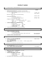
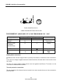
PRODUCT RANGE
1-
« BRUSHLESS » SERVODRIVES
TORQUE OR POWER
RANGES
•
•
•
2-
BRUSHLESS SERVOMOTORS, LOW INERTIA, WITH RESOLVER
Very high torque/inertia ratio (high dynamic performance machinery):
⇒ NX -HX - HXA
⇒ NX - LX
High rotor inertia for better inertia load matching:
⇒ HS - LS
Varied geometrical choice :
⇒ short motors range HS - LS
⇒ or small diameter motors : HD, LD
Voltages to suit different mains supplies :
⇒ 230V
three-phase for «série L - NX»
⇒ 400V, 460V
NX»
three-phase for
1 to 320 N.m
0,45 to 64 N.m
3,3 to 31 N.m
3,3 to 31 N.m
9 to 100 N.m
«série H -
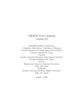
"DIGIVEX DRIVE" DIGITAL SERVOAMPLIFIERS
⇒ SINGLE-AXIS
DSD
⇒ COMPACT SINGLE-AXIS
DµD, DLD
⇒ POWER SINGLE-AXIS
DPD
⇒ MULTIPLE-AXIS
DMD
"PARVEX MOTION EXPLORER" ADJUSTING SOFTWARE
SPINDLE DRIVES
•
•
3-
SPINDLE SYNCHRONOUS MOTORS
⇒ "HV" COMPACT SERIES
⇒ "HW" ELECTROSPINDLE,frameless, water-cooled motor
From 5 to 110 kW
up to 60,000 rpm
"DIGIVEX" DIGITAL SERVOAMPLIFIERS
DC SERVODRIVES
•
•
•
4-
"AXEM", "RS" SERIES SERVOMOTORS
"RTS" SERVOAMPLIFIERS
"RTE" SERVOAMPLIFIERS for DC motors + resolver giving position
measurement
0.08 to 13 N.m
SPECIAL ADAPTATION SERVODRIVES
•
•
5-
"EX" SERVOMOTORS for explosive atmosphere
"AXL" COMPACT SERIES SERVOREDUCERS
POSITIONING SYSTEMS
•
•
•
•
Numerical Controls « CYBER 4000 » 1 to 4 axes
"CYBER 2000" NC 1 to 2 axes
VARIABLE SPEED DRIVE - POSITIONER
⇒ SINGLE-AXIS
DSM
⇒ POWER SINGLE-AXIS
DPM
⇒ MULTIPLE-AXIS
DMM
ADJUSTMENT AND PROGRAMMING SOFTWARE PARVEX MOTION EXPLORER
5 to 700 N.m
DIGIVEX Little Drive Servoamplifier
CONTENTS
SAFETY INSTRUCTIONS
……………………………………………………………………………5
PRODUCT RANGE
2
1. GENERAL
7
1.1 Digital Servodrive
1.2 General Characteristics
1.3 Operating Principle
1.3.1
Block diagram
1.3.2
Power supply functions
1.3.3
Servomotor control functions
1.3.3.1 Presentation
1.3.3.2 Functions and block diagram
1.3.3.3 Forcing logic inputs
1.3.3.4 Stimuli / oscilloscope functions
1.3.3.5 Speed ramp function
1.3.3.6 logic outputs
1.3.3.7 Brake action
1.3.3.8 Monitoring reasons for stoppage
1.3.3.9 General characteristics of the DIGIVEX Little Drive
1.4 Compliance with Standards
2. ENERGY DISSIPATION
2.1 Braking Energy Dissipation
2.1.1
Calculating the power to be dissipated in the braking resistor
2.1.2
Braking energy dissipation
2.1.3
Braking capacity and module losses.
1
PVD 3530 GB 01/2005
7
7
8
8
10
10
10
10
12
12
12
14
14
15
15
16
17
17
17
17
18
DIGIVEX Little Drive Servoamplifier
2.2
DLD paralleling
19
3. DIMENSIONS, ASSEMBLY, MASS, LABELLING,
CODING
3.1
3.2
Dimensions, Assembly and Mass
Labelling and Coding
4. ELECTRICAL CONNECTIONS
4.1 General Wiring Requirements
4.1.1
Appliance handling
4.1.2
Electromagnetic compatibility
4.1.3
DIGIVEX Little Drive Sub-D connectors
4.2 Standard Connection Diagram
4.3 Description of Terminal Blocks and Sub-D Connector
4.3.1
Terminal blocks B1, B2, B3, B4
4.3.2
Sub-D connectors X1, X2, X3, X4
4.3.2.1 Sub-D connector table
4.3.2.2 Sub-D connector X1:"Resolver"
4.3.2.3 Sub-D connector X2: Inputs / Outputs
4.3.2.4 Sub-D connector X3: encoder emulation
4.3.2.5 Encoder emulation cable
4.3.2.6 Sub-D connector X4 : RS232
4.4 Connection Details
4.4.1
Main supply characteristics
4.4.2
Power component dimensions
4.4.3
Auxiliary power supply
4.4.4
Terminal block B1: brake supply
4.4.5
Earth connection to the chassis
4.4.6
Short-circuit capacity (UL 508 C certification)
4.4.7
Fuse specifications (UL 508 C certification )
4.5 Connecting Servomotors
4.5.1
Power cable definition
4.5.2
Motor end connection
4.5.3
Resolver connection
4.5.4
Automatic control Input / Output connection
4.6 Accessories and Tools
4.6.1
Cables
2
PVD 3530 GB 01/2005
20
20
22
23
23
23
23
24
24
29
30
30
30
31
33
36
36
38
38
38
39
39
40
40
40
40
41
41
47
49
50
50
50
DIGIVEX Little Drive Servoamplifier
5. AUTOMATIC CONTROL INPUT / OUTPUT
FUNCTIONS AND CHARACTERISTICS
5.1 Input / Output Characteristics
5.1.1
Logic inputs
5.1.2
Logic outputs
5.1.3
Speed set point input
5.1.4
Current limitation input
5.1.5
Analog outputs
5.1.6
Encoder emulation
5.2 RESET and Contactor Control
5.3 Initilialization Sequence
5.4 Stop Sequence
5.4.1
Normal stoppage
5.4.2
Stoppage due to a fault
51
51
51
51
52
53
53
54
56
57
57
57
57
6. SERVO-CONTROL PARAMETER FUNCTION AND
SETTING
58
6.1 Servocontrol Parameter Functions
6.1.1
List of parameters
6.1.2
Regulation selection: current, proportional, PI, PI²
6.1.3
Integration stoppage
6.1.4
Speed scaling
6.1.5
Filtering frequency
6.1.6
Predictors
6.2 Inputting Parameters
6.3 Setting with DIGIVEX PC Software
6.3.1
Outline
6.3.2
internal variables
6.3.3
Entering parameters via DIGIVEX PC software
6.3.4
Setting loop parameters for speed regulation
6.3.5
Setting predictors
6.3.6
Setting current regulation parameters
6.3.7
Other characterization parameters
58
58
58
61
61
61
62
64
64
64
65
66
66
70
74
74
7. COMMISSIONING - SERVO-CONTROL PARAMETER
SETTING - DETECTING REASONS FOR STOPPAGE 75
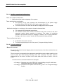
7.1 Start-up Sequence
7.1.1
Preliminary checks
75
75
3
PVD 3530 GB 01/2005
DIGIVEX Little Drive Servoamplifier
Commissioning with DIGIVEX PC software
7.1.2
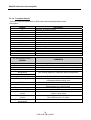
7.2 Detecting Reasons for Stoppage
7.2.1
Fault display - drive function
7.2.1.1 Handling operational malfunctions
7.2.1.2 Current monitoring
7.2.1.3 Temperature monitoring
7.2.1.4 Monitoring the DC Bus voltage
7.2.1.5 Other monitoring
7.2.1.6 7-segment display
7.2.1.7 Corrective actions
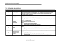
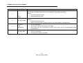
7.3 Defaults description
8. APPENDIX
75
76
76
77
77
78
78
78
79
80
81
83
Characteristics and dimensions subject to change without notice.
YOUR LOCAL CORRESPONDENT
SSD Parvex SAS
8 Avenue du Lac / B.P 249 / F-21007 Dijon Cedex
Tél. : +33 (0)3 80 42 41 40 / Fax : +33 (0)3 80 42 41 23
www.SSDdrives.com
4
PVD 3530 GB 01/2005
DIGIVEX Little Drive Servoamplifier
SAFETY
Servodrives present two main types of hazard :
- Electrical hazard
Servoamplifiers may contain non-insulated live AC or DC
components. Users are advised to guard against access to live
parts before installing the equipment.
Even after the electrical panel is de-energized, voltages may be
present for more than a minute, until the power capacitors have
had time to discharge.
Specific features of the installation need to be studied to prevent
any accidental contact with live components :
- Connector lug protection ;
- Correctly fitted protection and earthing features ;
- Workplace insulation
(enclosure insulation humidity, etc.).
General recommendations :
• Check the bonding circuit;
• Lock the electrical cabinets;
• Use standardised equipment.
- Mechanical hazard
Servomotors can accelerate in milliseconds. Moving parts must be
screened off to prevent operators coming into contact with them.
The working procedure must allow the operator to keep well clear
of the danger area.
All assembly and commissioning work must be done by qualified
personnel who are familiar with the safety regulations (e.g. VDE
0105 or accreditation C18510).
5
PVD 3530 GB 01/2005
DIGIVEX Little Drive Servoamplifier
Upon delivery
All servoamplifiers are thoroughly inspected during manufacture and tested at length before
shipment.
•
•
Unpack the servoamplifier carefully and check it is in good condition.
Also check that data on the manufacturer's plate complies with the data on the order
acknowledgement.
If equipment has been damaged during transport, the addressee must file a complaint with the
carrier by recorded delivery mail within 24 hours.
Caution:
The packaging may contain essential documents or accessories, in particular :
• User Manual,
• Connectors.
Storage
Until installed, the servoamplifier must be stored in a dry place safe from sudden temperature
changes so condensation cannot form.
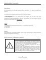
Special instructions for setting up the equipment
CAUTION
For this equipment to work correctly and safely it must be
transported, stored, installed and assembled in accordance with
this manual and must receive thorough care and attention.
Failure to comply with these safety instructions may lead to
serious injury or damage.
The cards contain components that are sensitive to electrostatic
discharges. Before touching a card you must get rid of the static
electricity on your body. The simplest way to do this is to touch a
conductive object that is connected to earth (e.g. bare metal
parts of equipment cabinets or earth pins of plugs).
6
PVD 3530 GB 01/2005
DIGIVEX Little Drive Servoamplifier
1. GENERAL
1.1 Digital Servodrive
All of the drives comprise:
Brushless servomotors with permanent magnets, sine-wave e.m.f. and resolver-based position
measurement (NX, LX, LS, LD range servomotors)
A box-type electronic control system including:
A power supply function for (depending on the model):
- 230 V single-phase mains supply or 230 V three-phase mains
supply
A control function corresponding to the servomotor (power and resolver) for spindle drive motor
control.
This module also controls energy discharge via internal.
Two connection options are available for these servomotors:
Terminal box + resolver connector.
Power connector + resolver connector.
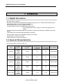
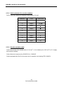
1.2 General Characteristics
Input voltage rating: 230V (see § 4.4.1)
TYPE
DLD 2/4
DLD 4/8
DLD 2/4
DLD 4/8
DLD 7.5/15
MAINS
SUPPLY
230 V –
singlephase
50/60 Hz
230 V –
singlephase
50/60 Hz
230 V –
threephase
50/60 Hz
230 V –
threephase
50/60 Hz
230 V –
threephase
50/60 Hz
CONTROLLABLE
POWER
SINE PEAK
PERMANENT
CURRENT
375 W
2A
4A
DLD13M02R
750 W
4A
8A
DLD13M04R
375W
2A
4A
DLD13002R
750W
4A
8A
DLD13004R
1,5kW
7.5 A
15 A
DLD13007R
7
PVD 3530 GB 01/2005
PEAK
MAXIMUM REF. PARVEX
CURRENT
DIGIVEX Little Drive Servoamplifier
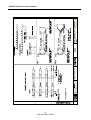
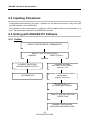
1.3 Operating Principle
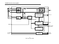
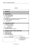
1.3.1 Block diagram
The block diagram shows two parts:
A power supply section providing dc voltage to the power bridge and auxiliary power supplies
(regulation, fans).
one part for axis control and monitoring control.
8
PVD 3530 GB 01/2005
DIGIVEX Little Drive Servoamplifier
L1/L
MOTOR
L2/N
L3
CTN
U
V
MOTOR
POWER
W
POWER
BUS VOLTAGE
PROTECTIONS
MANAGEMENT
DRV OK
AUX 1
AUXILIARIES
AUX 2
CHOPPED
SUPPLY
POWER OK
AXE
OK
+/- 15V
5V
DRIVE
REGULATION
RESET
INIT
C=0
RESOLVER
SUB-D
THERMAL
PROTECTION SUB-D I/O AND
SET POINT
FANS
24V BRAKE
SUPPLY
MONITORING BRAKE
VOLTAGE
9
PVD 3530 GB 01/2005
24V
BRAKE
DIGIVEX Little Drive Servoamplifier
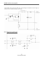
1.3.2 Power supply functions
Receives the 230 V mains supply through terminal block B3 and converts it into a 325V dc
voltage.
Receives the 230V monophase mains supply through the same B3 terminal block for powering
the auxiliary power supplies (+/-15V, 5V) required by safety regulations.
May receive a 24 V supply via terminal block B1 for powering the motor brake.
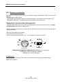
1.3.3 Servomotor control functions
1.3.3.1 Presentation
The DIGIVEX Little Drive (DLD) servo-amplifier is a 4-quadrant, transistor control module for
controlling (brushless) synchronous motors with resolvers.
NX, LX, LS, LD spindle drive motors. See separate documentation (PVD3407 and PVD3535).
The customization of the motor - resolver unit and the setting of the servocontrol parameters are
carried out using a PC with DIGIVEX software (PME software, DIGIVEX module), under
Windows.
These parameters are stored in an EEPROM permanent memory.
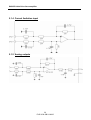
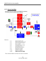
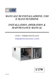
1.3.3.2 Functions and block diagram
See next page. The diagram shows the main drive functions and the setting parameters.
10
PVD 3530 GB 01/2005
DIGIVEX Little Drive Servoamplifier
On the right of the diagram, the motor - resolver - power section.
Parameters can be set for:
⇒ the choice of motor, which dictates the drive rating.
⇒ the general characteristics of the resolver.
The choice of the motor - drive combination determines a number of parameters: current
limitation, I2 = f(t) protection, standard servo-control parameters.
Ahead of current control.
♦ Second order filter for reducing the effect of high-frequency resonance
♦ External reduction of current limitation
Resolver numerical processing (non parametric) and the encoder emulation function (number of
lines adjustable from 1 to 16384).
Choice of type of regulation: torque or speed.
In speed loop. Parameters can be set for :
⇒ maximum speed for the application (limited by the maximum motor speed).
⇒ scaling (1 V = N rpm).
⇒ choice of corrector type: proportional, proportional and integral, proportional and
double integration.
Predictive actions associated with speed control.
These actions, acting outside the speed loop, directly affect torque. As they are external they
have little effect on loop stability. However, they allow anticipated actions, without waiting for the
speed loop reaction.
The predictive actions (or predictors) are:
Gravity: compensation for vertical masses.
Dry friction: a friction force value is fixed. The corresponding torque set point is applied, its sign
being that of the speed set point.
Viscous friction: compensation for friction forces that are proportional to speed (hydraulic or
electrical system drive).
Acceleration: changes in the speed set point (drift) are monitored and direct action is taken on
the torque set point via a coefficient K, the inertia image.
The analog input speed reference (13 bits + sign), non parametric.
On the left of the block diagram, the set of logic and analog inputs / outputs.
The parameter setting software is used:
for allocating some of these Inputs / Outputs.
for forcing them to a logic status. The inputs are then disconnected from the outside.
11
PVD 3530 GB 01/2005
DIGIVEX Little Drive Servoamplifier
1.3.3.3 Forcing logic inputs
The software allows the logic input to be forced to a value. Consequently, via the software, the
SPEED RANGE, CW, CCW, TORQUE inputs are able to:
"disconnect" them from the physical input.
force them by software to 0 or 1.
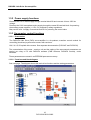
1.3.3.4 Stimuli / oscilloscope functions
Certain functions integrated in the drive allow the speed set point to be excited: dc voltage,
square (response at one scale), sine.
These stimuli are activated by a PC. Their result, stored in the amplifier, can be seen on the PC
screen by using the oscilloscope function (a maximum of 4 variables can be displayed
simultaneously via the PME DIGIVEX software).
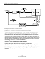
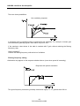
1.3.3.5 Speed ramp function
A ramp function is integrated into the drive unit for versions of software above AP516V07, running
with PME version 4.04 or above. This function is used to create time dependent linear speed
ramps. Parameters can be set in “Servo-control settings” under the “ramp” tab:
- Times t1, t2, t3, and t4 can be programmed from 0 to 1000s.
- Speeds Vp and Vn can be programmed from 0 to 50,000 rpm.
Comment:
Vp and Vn are points on the ramp; they can be defined outside of maximum motor speed.
However, servo-controls will limit the motor speed to the maximum authorized speed.
12
PVD 3530 GB 01/2005
DIGIVEX Little Drive Servoamplifier
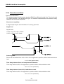
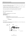
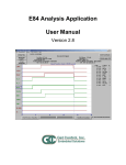
How the ramp operates:
The ramp input can either be the analog input instruction or the stimuli generator as shown below:
Input
instruction
Scaling
Speed
ramp
To speed
servo-controls
Stimuli
generator
ON/OFF stimuli
In the event that the input is analog, scaling is carried out by the input instruction product (V) * speed
range for 1V, the speed range for 1 volt can be found in the servo-control dialogue box.
Ramp activation is validated by the information “TORQUE=1” (enable torque activated).
Therefore, the ramp operates as soon as the zero torque information is unlocked and an operating
direction (CW or CCW) selected. When CW or CCW is deactivated, the motor decelerates in
accordance with the pre-set ramp which means that CW or CCW cannot be selected as
mechanical stops.
Important remarks:
- When “TORQUE” is successively deactivated and reactivated, the speed is reduced to
zero prior to following the progression of the ramp.
- The ramp function must be deactivated when a DLD with digital control is used to carry
out a check on the axis position.
13
PVD 3530 GB 01/2005
DIGIVEX Little Drive Servoamplifier
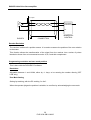
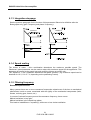
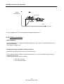
1.3.3.6 logic outputs
Speed detection
The OUT1 output status acts in the following manner:
Criterion
OUT1
Speed < Threshold (OUT1)
1
Speed > Threshold (OUT1)
0
NB: 19 rpm ≤ threshold (OUT1) ≤ 100,000 rpm
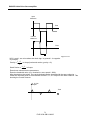
Speed reached
OUT2 output changes to 1 status when the motor speed is within the range given by + or the Threshold (OUT2) value:
± Limit (OUT2)
± Limit (OUT2)
(input instruction – threshold (OUT2) < actual speed < input instruction + threshold (OUT2)
NB: 48 rpm ≤ threshold (OUT2) ≤ 5252 rpm
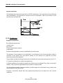
1.3.3.7 Brake action
The drive can be declared in the parameters with a brake function.
The 24 V brake supply (terminal block B1) is monitored by the drive.
24 V present: Axis under torque. Removal of limitation of 90% of rated motor current.
24 V absent: Axis at reduced torque with 90% of rated motor current.
The brake engage or release order is in no event given by the drive but by the external control.
The control can monitor the drive outputs indicating zero speed to decide whether or not to apply
the brake.
14
PVD 3530 GB 01/2005
DIGIVEX Little Drive Servoamplifier
1.3.3.8 Monitoring reasons for stoppage
This monitoring may, through strategic choice, entail either stoppage or reduced performance for
certain faults related to current.
Variables monitored :
Mean drive current.
Output current (short-circuit).
Dissipater temperature.
Motor temperature.
Ambient temperature.
Overspeed.
No resolver.
Maximum and minimum dc bus voltages.
1.3.3.9 General characteristics of the DIGIVEX Little Drive
Power reduction with altitude
Operating temperature
relative humidity
Storage temperature
Chopping frequency
Current bandwidth
Speed bandwidth
Minimum speed
Maximum speed
Speed static precision for load
variation from 0 to In and for
rated voltage of DIGIVEX Little
Drive
Electrical protection
Mechanical protection
Pollution degree
Other monitoring
Above 1000 m, service power falls by 1% for every 100 m up
to a maximum altitude of 4000 m
Normal use: 0 - 40°C
Above 40°C, service power falls by 20% for every 10°C up to
a maximum temperature of 60°C.
The variable speed drive stops when the ambient temperature
exceeds 60°C.
85% (without condensation)
-30°C to +85°C
8 kHz
600Hz to -3dB
Up to 200Hz
Minimum speed 0.05 rpm or 1/8000th of maximum speed
Driven by DIGIVEX : 100 000 rpm
With analog set point: 1% whatever the speed
Electrical isolation of power bridge
Mean current protection depending on drive rating
Pulse current protection of drive and motor
rms current protection of motor
Protection against short circuits at bridge output
IP20 under IEC 529
UL : 2
To rise in a surrounding wall
Motor temperature
Drive temperature
Resolver power supply
Brake supply
15
PVD 3530 GB 01/2005
DIGIVEX Little Drive Servoamplifier
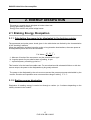
1.4 Compliance with Standards
DIGIVEX Little Drive
CE Marking
DIGIVEX Little Drive products have the CE marking under the European Directive 89/336/EEC as
amended by Directive 93/68/EEC on electromagnetic compatibility as well as under the Electrical
Safety Directive or Low Voltage Directive 73/23/EEC amended by Directive no. 93/68/EEC.
The Directive concerning electromagnetic compatibility invokes the harmonized generic standards
EN 50081-2 of December 1993 (Electromagnetic Compatibility – Emission Generic Standard –
Industrial Environment) and EN 50082-2 of June 1995 (Electromagnetic Compatibility – Immunity
Generic Standard – Industrial Environment). These two harmonized generic standards are based
on the following reference standards:
•
•
•
•
•
•
EN 55011 of July 1991: Radiated and line conducted emissions.
ENV 50140 of August 1993 and ENV 50204: Immunity to radiated electromagnetic fields.
EN 61000-4-8 of February 1994: Power frequency magnetic fields.
EN 61000-4-2 of June 1995: Electrostatic discharge.
ENV 50141 of August 1993: Disturbances induced in cables.
EN 61000-4-4 of June 1995: Rapid transients.
The Low Voltage Directive groups all the electrical safety standards together including the EN
60204-1 Standard which covers electrical fittings on industrial machinery.
Compliance with the reference standards above implies observance of the wiring instructions and
diagrams provided in this technical documentation which accompanies all equipment.
Incorporation in a machine
The design of this equipment allows it to be used in a machine subject to Directive 98/37/EC of
22/06/98 (Machinery Directive), provided that its integration (or incorporation and/or assembly) is
done in accordance with trade practices by the machine manufacturer and in accordance with the
instructions in this booklet.
UL Certification
DIGIVEX Little Drive products are covered by UL and cUL certificate (see section 8).
16
PVD 3530 GB 01/2005
DIGIVEX Little Drive Servoamplifier
2. ENERGY DISSIPATION
The energy a module has to dissipate is broken down into:
Energy generated by braking.
Energy from rectifier and power bridge losses.
2.1 Braking Energy Dissipation
2.1.1 Calculating the power to be dissipated in the braking resistor
The permanent and pulse power levels given in the table below are limited by the characteristics
of the "breaking" resistors.
When the application includes intensive cycles or long-duration decelerations, the mean power to
be dissipated by each axis must be calculated.
2
P in Watts =
J⎛ N ⎞
⎜
⎟ .f
2 ⎝ 9.55 ⎠
J : Moment of inertia of the servomotor and the related load in kgm².
N : Angular speed of motor shaft at start of braking, in rpm.
-1
f : repeat frequency of braking cycles in s .
This formula is for the least favourable case. For a mechanism with substantial friction or with low
reverse output, the power to be dissipated may be greatly reduced.
.
The power to be dissipated by the axis must not exceed the permanent power admissible by the
resistor. Duration and repetition must not exceed the ratings in table § 2.1.3.
2.1.2 Braking energy dissipation
Dissipation of breaking energy is carried out through a resistor (or 2 resistors depending on the
calibre) situated in the module.
17
PVD 3530 GB 01/2005
DIGIVEX Little Drive Servoamplifier
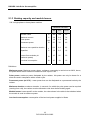
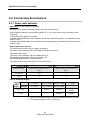
2.1.3 Braking capacity and module losses.
230 V single-phase or three-phase modules.
MODULE RATING
2/4
4/8
7.5/15
Resistor value
Ω
100
100
50
Maximum current
A
3.8
3.8
7.6
Pulse power
kW
1.2
1.2
2.4
Permanent power
W
20
30
40
Maximum non repetitive duration
s
0,2
0,2
0,2
Repetition
%
1,6
2,5
1,6
Losses from modules (at
maximum power)
W
15
25
50
Low level consumption
W
10
10
10
Definitions
Maximum power: Maximum power drawn, resistance connecting is carried out at 360V, hence,
the power drawn has a maximum resistance value equal to 360.
Pulse power: maximum power dissipated by the resistor, this power can only be drawn for a
short time and in compliance with a certain cycle.
Permanent power (to 25°C) : mean power that can be dissipated on a permanent basis by the
resistor.
Maximum duration: maximum duration, in seconds, for which the pulse power can be required
(starting from cold); the resistor must be allowed to cool down before braking again.
Module losses: losses specific to the module, the value shown in the table is that obtained when
the module is used at maximum power.
Low-level consumption: consumption of the low-level power supplies in Watts.
18
PVD 3530 GB 01/2005
DIGIVEX Little Drive Servoamplifier
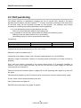
2.2 DLD paralleling
The braking capacity of applications requiring the use of several DLD, placed in the same
electrical control cabinet, can be increased (1) (2). It is only a question of linking the DC buses from
all the DLD using the B4 connector provided for this purpose. The operation quite simply
comprises of combining the braking capacities of all the appliances.
(1) If cycle simultaneity does not exist between the axes:
There is no synchronization between the braking axes
(2) It is possible to use the axes’ synchronism according to the following cycles:
Braking of one axis whilst another axis is accelerating.
(the braking energy is used to accelerate the other axis).
Connections:
Connector
B4
B4
Contact
1
2
Function
DC+
DC-
Connections are carried out from DC+ to DC+, DC- to DC-.
Maximum number of parallel axes: 6.
Connecting cover cables section: 1mm² minimum (cable reference: UL 1015 AWG16)
Maximum length of connection: 300mm of connecting cable (connection to be kept as short as
possible).
Every axis must remain connected to the electric mains supply (it is absolutely forbidden to
connect 1 axis to the mains and then use the DC bus link as a power supply for the axes
connected via this connection).
Follow the electrical connection plans on pages 25 and 26, especially with regard to all axis and
line fuses.
The axes linked together by the DC buses must be connected to the same electric mains supply.
A clear 10mm must be spaced between each axis.
Plan of dimensions: see page 19
Electrical connection plans: see pages 25 and 26.
19
PVD 3530 GB 01/2005
DIGIVEX Little Drive Servoamplifier
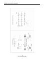
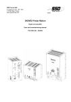
3. DIMENSIONS, ASSEMBLY, MASS,
LABELLING, CODING
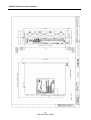
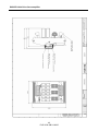
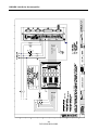
3.1 Dimensions, Assembly and Mass
See the following pages, drawing numbers - FELX 306455
20
PVD 3530 GB 01/2005
DIGIVEX Little Drive Servoamplifier
21
PVD 3530 GB 01/2005
DIGIVEX Little Drive Servoamplifier
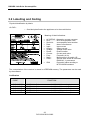
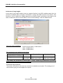
3.2 Labelling and Coding
Physical identification by labels:
On DLD :
∗ One label plate fixed to the appliance as in the model below:
Meaning of label indications:
•
•
•
•
•
•
•
•
•
•
•
•
•
AC SERVO : Alternating current converter
DLD - - - - - : DLD servo-amplifier code
Serial Nr :
servoamplifier serial number
Date :
date of manufacture
Input :
Input current
Output :
Output current
Voltage :
Voltage mean value
Phase :
Phase number
Current :
Current peak value
Freq.:
Frequency in Hz
Motor :
Motor power in W and in HP
Class :
Service class under NF standard
EN60146, 1= permanent
IP20
Protection indice acording to
NF EN 60529 standard
The customization of the resolver is stored in a EEPROM memory. The parameters can be read
by the software
Codification
CODE
DLD13M02R
DLD13M04R
DLD13002R
DLD13004R
DLD13007R
FUNCTION
DIGIVEX Little Drive
DIGIVEX Little Drive
DIGIVEX Little Drive
DIGIVEX Little Drive
DIGIVEX Little Drive
monoaxe
monoaxe
monoaxe
monoaxe
monoaxe
Ue 230V
Ue 230V
Ue 230V
Ue 230V
Ue 230V
22
PVD 3530 GB 01/2005
2/4A
4/8A
2/4A
4/8A
7,5/15A
single-phase
single-phase
three-phase
three-phase
three-phase
DIGIVEX Little Drive Servoamplifier
4. ELECTRICAL CONNECTIONS
4.1 General Wiring Requirements
4.1.1 Appliance handling
Please refer to the safety instructions given at the beginning of this booklet. It is strongly
recommended that personnel wait for the 7-segment display, situated on the front panel, to go off
before undertaking any intervention of the servoamplifier or servomotor.
4.1.2 Electromagnetic compatibility
EARTHING
Comply with all local safety regulations concerning earthing.
Utilize a metal surface as an earth reference plane (e.g. cabinet wall or assembly grid). This
conducting surface is termed the potential reference plate. All the equipment of an electrical
drive system is connected up to this potential reference plate by a low impedance (or short
distance) link. Ensure the connections provide good electrical conduction by scraping off any
surface paint and using fan washers. The drive will then be earthed via a low impedance link
between the potential reference plate and the earth screw at the back of the DIGIVEX Little
Drive. If this link exceeds 30 cm, a flat braid should be used instead of a conventional lead.
CONNECTIONS
Do not run low-level cables (resolver, inputs/outputs, NC or PC links) alongside what are termed
power cables (power supply or motor). Do not run the power supply cable and the motor cables
alongside one another otherwise mains filter attenuation will be lost. These cables should be
spaced at least 10 cm apart and should never cross, or only at right-angles.
Except for the resolver signals, all low-level signals will be shielded with the shielding connected
at both ends. At the DIGIVEX Little Drive end, the shielding is made continuous by the Sub-D
connector mechanism.
The motor cables are limited to the minimum functional length. The yellow and green motor
cable lead must be connected to the box or front panel terminal block with the shortest possible
link.
This usually means shielded motor cable is not required. Chokes may also be inserted into the
motor phase leads.
OTHER MEASURES
Self-inducting components must be protected against interference: brakes, contactor or relay
coils, fans, electro-magnets, etc.
23
PVD 3530 GB 01/2005
DIGIVEX Little Drive Servoamplifier
4.1.3 DIGIVEX Little Drive Sub-D connectors
In order to ensure the system is free from disturbances, it is essential for the rack to be properly
connected to the earth plane of the electrical cabinet and for the covers of the Sub-D connectors
to be EMI/RFI shielded (metal with shielding braid connection).
Make sure the Sub-D connectors and their covers are properly connected (lock screws fully
tight).
GROUND CONNECTION
Fold the shielding braid over the
cable sheath
Solder between the braid and the
green and yellow lead.
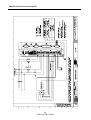
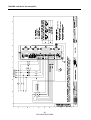
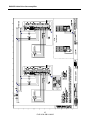
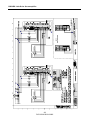
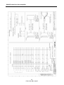
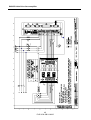
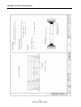
4.2 Standard Connection Diagram
See the drawings on the following pages
-
FELX 306198
FELX 306199
FELX 306460
FELX 306461
24
PVD 3530 GB 01/2005
DIGIVEX Little Drive Servoamplifier
25
PVD 3530 GB 01/2005
DIGIVEX Little Drive Servoamplifier
26
PVD 3530 GB 01/2005
DIGIVEX Little Drive Servoamplifier
27
PVD 3530 GB 01/2005
DIGIVEX Little Drive Servoamplifier
28
PVD 3530 GB 01/2005
DIGIVEX Little Drive Servoamplifier
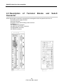
4.3 Description
Connector
of
Terminal
Blocks
and
Sub-D
All the input/outputs required for operation are arranged on the front panel in the form of:
- B1 brake power supply terminal.
- B2 motor terminal.
- B3 power supply and auxiliary power terminal.
- B4 DC Bus
- X1 RESOLVER connector.
- X2 INPUTS / OUTPUTS connector.
- X3 ENCODER connector
- X4 RS232 connector.
29
PVD 3530 GB 01/2005
DIGIVEX Little Drive Servoamplifier
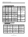
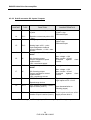
4.3.1 Terminal blocks B1, B2, B3, B4
ITEM
REF.
TERMINAL
B1/1
B1/2
BS+
BS-
B2/1
B2/2
B2/3
B2/4
B2/5
B2/6
B2/7
U
V
W
TH+
THBR+
BR-
B2/8
B3/1
B3/2
Aux1
Aux1
B3/3
B3/4
B3/5
L1/L
L2/N
L3
B3/6
Front Panel
Marking
FUNCTION
TERMINAL
BLOCK
TYPE
B1
24V input for
brake supply
Min 0,2 mm²
Unpluggable Max 2,5 mm²
screw-type flexible and rigid
lead
B2
Motor connection
B2
Motor thermal
protection
B2
Motor brake
B2
EARTH
B3
Low-level
supply
B3
Mains connection
For single-phase mains
only B3/3 and B3/4 are
to be connected
B3
EARTH
B4/1
DC+
B4
DC+ BUS
B4/2
DC-
B4
DC- BUS
TERMINAL
CAPACITY
Min 0,2 mm²
Unpluggable Max 2,5 mm²
screw-type flexible and rigid
lead
Min 2,5 mm²
Unpluggable
flexible and rigid
screw-type
lead
Min 0,2 mm²
Unpluggable Max 2,5 mm²
screw-type flexible and rigid
lead
unpluggable
screw type
Min 0.2 mm²
Max 2.5 mm²
flexible and rigid
lead
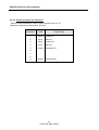
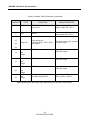
4.3.2 Sub-D connectors X1, X2, X3, X4
4.3.2.1 Sub-D connector table
Connectors with metal-plated or metallic covers.
ITEM REF.
CONNECTOR TYPE
(cable end)
FUNCTION
X1
RESOLVER
9-pin plug for
soldering
Resolver link
max. 0.5 mm² on
soldering barrel
X2
INPUTS/
OUTPUTS
25-pin plug for
soldering
Logic and
analog
inputs / output
max. 0.5 mm² on
soldering barrel
X3
ENCODER
9-pin socket for
soldering
Encoder emulation
output
max. 0.5 mm² on
soldering barrel
X4
RS232
9-pin plug for
soldering
PC link
max. 0.5 mm² on
soldering barrel
30
PVD 3530 GB 01/2005
MAX. CONDUCTOR
CROSS-SECTION
DIGIVEX Little Drive Servoamplifier
4.3.2.2 Sub-D connector X1:"Resolver"
DIGIVEX end connections, Sub-D 9 pin connector item ref. X1.
Maximum conductor cross-section: 0.5 mm²
CONTACT
TYPE
FUNCTION
1
Input
Cosine S1
2
Input
Sine S2
3
Input
Cosine S3
4
Input
Sine S4
5
Output
Excitation R1
Output
Excite R2/R3
6
7
8
9
31
PVD 3530 GB 01/2005
DIGIVEX Little Drive Servoamplifier
32
PVD 3530 GB 01/2005
DIGIVEX Little Drive Servoamplifier
4.3.2.3 Sub-D connector X2: Inputs / Outputs
CONTACT
TYPE
FUNCTION
1
EA1 +
Speed or current set point ±10V,
+ point
14
EA1 -
2
EA2 +
Speed or current set point ±10V,
- point
Analog input ±10V, + point
15
EA2 -
3
SA1
16
0V
4
SA2
17
0V
9
EL1 +
Analog input ±10V, - point
Input assigned to external
current limitation. +/-10V = max.
current
Analog output ±10V, + point
ANA1
0V of analog output
Output assigned to speed
measurement
10V = maximum speed
Analog output ±10V, + point
ANA2
0V of analog output
Output assigned to current
measurement
10V = maximum current
SPEED RANGE
CHARACTERISTICS
Analog conversion:
13 bits + sign
Differential input
Analog conversion:
9 bits + sign
Differential input
Analog conversion:
Max. voltage = 10V
Max. current = 10 mA
Protected
against
circuits.
short
Analog conversion:
Max. voltage = 10V
Max. current = 10 mA
Protected
against
circuits.
short
Type-1, optocoupled 24V
logic inputs to IEC 1131-2.
Speed range choice
10
EL2 +
CW: enables clockwise rotation if
input is active (level 1)
(see characteristics on
following pages)
11
EL3 +
CCW: enables counter-clockwise These inputs must have a 24V
rotation if input is active (level 1) supply to have level 1.
EA = analog input, EL = logic input, SA = analog output, SL = logic output
33
PVD 3530 GB 01/2005
DIGIVEX Little Drive Servoamplifier
"Inputs / Outputs" Sub-D connector (continued)
CONTACT
TYPE
FUNCTION
CHARACTERISTICS
12
EL4 +
TORQUE: enables torque if
input is at 1
Optocoupled 24V type 1 logic
inputs under ICE 1131-2
5
EL+
RESET
Optocoupled 24V type 1 logic
inputs under ICE 1131-2
Logic 0V
Logic inputs OV
For EL1+, EL2+, EL3+, EL4+
and RESET
The logic inputs are common
via the 0V logic
SL1
DRV OK
Max. 50 mA, optocoupled
PNP 24V output
OUT1 speed detection
Max. 50 mA, optocoupled
PNP 24V output
OUT2 speed detection
Max. 50 mA, optocoupled
PNP 24V output
+24V power supply input
0V power supply input
Max. voltage: 35V
Max. current = 160mA
21
22
23
24
6
18
0V
Logic
7
SL2
19
0V
Logic
8
SL3
20
0V
Logic
+24V Logic
0V
Logic
13
25
EA = analog input, EL = logic input, SA = analog output, SL = logic output
34
PVD 3530 GB 01/2005
DIGIVEX Little Drive Servoamplifier
35
PVD 3530 GB 01/2005
DIGIVEX Little Drive Servoamplifier
4.3.2.4 Sub-D connector X3: encoder emulation
Sub-D 9-pin plug. Maximum conductor cross-section: 0.5 mm².
CONTACT
TYPE
FUNCTION
1
.
2
Output
Top 0
3
Output
A
4
Output
B
6
Output
Top 0
7
Output
A
8
Output
B
9
Input
0V
5
4.3.2.5 Encoder emulation cable
2
2
Cable formed from three twisted pairs of 0.14 mm , of one twisted pair of 0.5 mm for 5 V supply
and general shielding.
Cable reference recommend by PARVEX S.A., CB08307.
Cables equipped with Sub-D connectors can be supplied, see drawing FELX 304554.
36
PVD 3530 GB 01/2005
DIGIVEX Little Drive Servoamplifier
37
PVD 3530 GB 01/2005
DIGIVEX Little Drive Servoamplifier
4.3.2.6 Sub-D connector X4 : RS232
Maximum conductor cross-section: 0.5 mm²
Serial link configuration :
♦ 9600 bauds
♦ 8 data bits
♦ 1 start bit, 1 stop bit
♦ no parity
♦ no electrical isolation
♦ use an extension cable of 5 m maximum
SUB-D 9pts DIGIVEX
SUB-D 9pts PC
NC
1
TD (TXD) 2
RD (RXD) 3
NC
4
0V
5
NC
6
NC
7
NC
8
NC
9
NC= Not Connected
1
2
3
4
5
6
7
8
9
RD (RXD)
TD (TXD)
0V
This input is for linking with a computer (PC) for parameter loading and setting via the DIGIVEX
PC software.
4.4 Connection Details
4.4.1 Main supply characteristics
230 V single-phase or three-phase modules
PARAMETER
Frequency
Minimum voltage
Maximum voltage
Rated voltage
Dc voltage achieved
VALUE
47 - 63 Hz
92 V rms
253V rms
230V rms *
140 - 340V
* To guarantee mechanical power
- single or three-phase for 2/4 and 4/8 caliber
- Three-phase only for caliber 7,5/15
38
PVD 3530 GB 01/2005
DIGIVEX Little Drive Servoamplifier
4.4.2 Power component dimensions
one single drive
Applicable to components ahead of the DLD (fuses, cables, contactors, etc.), these dimensions
are dependent on:
Permanent current Î0 (sine wave peak) at slow motor speed, as given in the characteristics.
Electrical power of mains supply ≅ 1.1 U rms Î0
Eff.I power source = eff.mainsP x
1 in single-phase
0.65
eff.U 3
Eff.I power source = eff.mainsP x 1 in three-phase
0.8
eff.U 3
4.4.3 Auxiliary power supply
The power supplies required for the controls (+/- 15V, 5V, ventilators) are taken from an
intermediate direct-current voltage which can be:
Either obtained via a single-phase power source coming from the mains, bled off between 2
phases upstream from the main contactor (B3 terminal block input).
- please remember that the internal wiring is as follows:
THREE-PHASE
SINGLE-PHASE
- The auxiliary power source input must be taken between two phases (L1,L2), (L2,L3) or (L1,L3)
in the case of three-phase and between (L,N) in the case of single-phase, upstream from the
main contactor (please refer to the relevant connection diagrams: FELX 306198 for single phase
and FELX 306199 for three-phase).
- Or obtained via an independent single-phase power source, and connected to the B3 terminal
block. In this case, this power source must be isolated from the mains via a transformer
(secondary 230 +/-10% 100VA).
- Or obtained from the intermediary mains voltage, through diodes (B3 is not
connected). In this option (not recommended), the cutting-off of the mains power
source leads to the loss of the low level power sources and, in particular, the pulses
generated by the "encoder emulation" option.
39
PVD 3530 GB 01/2005
DIGIVEX Little Drive Servoamplifier
Clarification:
1) Connection of the auxiliary power source is not compulsory because it is fed internally by
the direct bus. Connection proves necessary if we want to save the position and the state
through the encoder output (emulation) when for safety reasons, the mains power is turned
off.
2) If the auxiliary power source is used, it is essential for it to be connected to the same
phases (2 out of 3 for three-phase) as the mains power supply (see recommended
diagram- FELX 306198 for single phase and FELX 306199 for three-phase.), to avoid
damage to the appliance.
If this is not possible, this auxiliary power source can possibly originate from another circuit, but it
must, imperatively, be isolated from the system using a transformer whose secondary will not be
earthed. The voltage of the transformer secondary must be identical to the mains voltage (230V
for mono appliances or three-phase 230V).
4.4.4 Terminal block B1: brake supply
This terminal block is also able to receive a 24V power source voltage for the brake fitted to the
motor. It is supplied to the B2 motor terminal.
The customer is responsible for supplying an isolated, regulated, and filtered 24VDC voltage.
Protection against overvoltage by 1 Joule varistor, this protection is effective from 30V.
A 4A UL fuse must be used (UL recommendation) for +24VDC voltage.
4.4.5 Earth connection to the chassis
Chassis earth:
The cable cross-section must usually be identical to that of the mains connection in order to
comply with standards in force.
4.4.6 Short-circuit capacity (UL 508 C certification)
“Suitable For Use on a circuit capable of delivering not more than 5000 rms symmetrical amperes
230 volts maximum”
4.4.7 Fuse specifications (UL 508 C certification )
The auxiliary input must be protectected by the fuses F2 type : ATDR2, 2A, 600V class cc
made by Ferraz SHAWMUT.
40
PVD 3530 GB 01/2005
DIGIVEX Little Drive Servoamplifier
4.5 Connecting Servomotors
4.5.1 Power cable definition
Attention! Only use copper core cables
The motor / drive power connection cables will have as a minimum:
three isolated conductors connected to phases U, V, W. Cross-sections as in the table on the
next page.
1 earth conductor (green and yellow).
2 twisted and shielded pairs for connection of the motor thermal protection. Cross-section in the
order of 1mm².
2 twisted and shielded pairs for connection of the holding brake (if present). Cross-section in the
order of 1mm².
Power cable cross-section
The cross-sections given are for copper conductors.
The cable cross-sections given in the table below take account of:
The rated drive current.
The motor / drive distance, service voltage loss = RI.
The ambient temperature, cable Joule losses = RI².
the standardized increase in cable sections.
The cable section to be used is given in the table below
Distance Î 0m
50m 50m
120m
DIGIVEX rating
Copper cable cross-section in
mm²
Copper cable cross-section in
mm²
2/4 and 4/8
0.5
1
7.5/15
1
2
Use for standard lengths
Normal
L ≤ 20 m
20 < L ≤ 30m
30 < L ≤ 50m
L > 50m
Shielded
L ≤ 15 m
15 < L ≤ 20 m
20 < L ≤ 50 m
L > 50m
2/4 – 4/8
-
DSF01
DSF01
7.5/15
-
-
DSF01
Copper
cable
length
•
•
See table
below
See table
below
DSF01: three inductances of 50 mH weakened to rise on rail DIN
For lengths superior to 50 m, consult us.
41
PVD 3530 GB 01/2005
DIGIVEX Little Drive Servoamplifier
In the case of long lengths
In the case of long cable lengths, there is a special function in the DLD variable speed drive for
versions of software above or equal to AP516V07, running with PME version 4.04 or above. This
function is used to adapt the variable speed drive switching mode according to the length of the
cable. Parameters can be set with PME in “Servo-control settings” under the hardware tab.
There are three possibilities:
-
Default values (8kHz) + PWM mode 1
4kHz + PWM mode 1
4kHz + PWM mode 2
The parameters to be applied are as follows:
Cable length
(shielded and non-shielded)
Settings
L< 50m
50m < L < 80m
80m < L < 120m
Default
4kHz
4kHz
value+DSF01 PWM mode1+DSF01 PWM mode 2+DSF01
Only modify the parameters in these specific cases. Follow any modification by shutting
down and restarting the variable speed drive.
Connection by connector
The power connection on the motor by connector is available as an option. The mating part of
the connector (plug) can be supplied on request.
42
PVD 3530 GB 01/2005
DIGIVEX Little Drive Servoamplifier
43
PVD 3530 GB 01/2005
DIGIVEX Little Drive Servoamplifier
44
PVD 3530 GB 01/2005
DIGIVEX Little Drive Servoamplifier
45
PVD 3530 GB 01/2005
DIGIVEX Little Drive Servoamplifier
46
PVD 3530 GB 01/2005
DIGIVEX Little Drive Servoamplifier
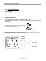
4.5.2 Motor end connection
Power connection
There are two possibilities for connection:
Terminal block + resolver connector.
Power connector + resolver connector.
Terminal block connection
For the terminal block, the clamping nuts and washer come in a bag
Take care when fitting the lugs not to loosen the connecting leads between the motor and the
terminal block.
The power connection lugs are to be inserted between
the striated washer and the flat washer.
Digpl3.D
Motor direction of rotation: by wiring as recommended, a positive set point applied to the drive
entails clockwise rotation (viewed from the power shaft end).
ALIMENTATION/SUPPLY/SPEISUNG
U Phase U
V Phase V
V
U
1
2
W
3
4
W Phase W
1 Optional brake +24 V
2 Optional brake
FREIN/BRAKE
BREMSE
Thermal
sensor
3 Thermal sensor
4 Thermal sensor
47
PVD 3530 GB 01/2005
cable ≥ 1mm²
0V
cable ≥ 1mm²
DIGIVEX Little Drive Servoamplifier
PLUG 220065R1610/1611
CABLE CROSS-SECTION FOR PLUGS
PLUG 220065R1610 : power & earth: 0.14 - 1.5 mm². Brake & thermal: 0.14 - 1 mm²
PLUG 220065R1611 : power & earth: 0.75 - 2.5 mm². Brake & thermal: 0.14 - 1 mm²
FUNCTION
BRAKE +
BRAKE THERMAL
PROTECTION
THERMAL
PROTECTION
PLUG PINS
220065R1610/R1611 220065R3610/R3611
A
+
B
C
1
D
2
EARTH
U2
V2
W2
2
1
4
3
U
V
W
CABLE COLOR
Green-red
Green-blue
Orange
Yellow
Yellow-Green
Black
White
Red
Holding brake connection
Brushless motors can be equipped with a specially sized brake to maintain the axis immobilized.
If
24 V ±10% dc voltage is applied across the brake terminals, the brake disc is free and the motor
can rotate.
The 24 V dc supply used for brake control must be regulated and filtered. The brake is to be
connected to terminals B2/6 and B2/7.
Thermal protection connection
The two terminals of the thermal sensor located in the motor terminal box are to be connected to
B2/4 and B2/5.
48
PVD 3530 GB 01/2005
DIGIVEX Little Drive Servoamplifier
4.5.3 Resolver connection
The resolver is a high-precision sensor (±10 angular minutes as standard) which must be wired
carefully:
Separate power cable routing.
Cable twisted and shielded in pairs (no general shielding). The shielding must be linked to the
metal SUB-D plug cover. The shielding must not be linked to the motor side.
PARVEX SAS. can supply this cable in either of two forms:
Separate cable, in this case wire as in the drawing below.
Cable fitted with Sub-D plug at the drive end and connector at motor end. This solution is highly
recommended as the cable is ready for use.
Maximum distance between the resolver and the DIGIVEX Little Drive: 50 m (Please ask about
greater distances).
Maximum permissible cross-section:
by the Sub-D connector: 0.5mm².
by the connector removable plug: 0.14 - 1 mm² (solder- or crimp-fit contacts)
Viewed from F
RESOLVER CONNECTOR REMOVABLE PLUG (motor end connector)
220065R4621 (solder-fit contacts - standard)
220065R1621 (crimp-fit contacts)
For XD motors :
Connect by Sub-D connector under rear cover (cable routed through special cable gland).
Please ask for details.
49
PVD 3530 GB 01/2005
DIGIVEX Little Drive Servoamplifier
4.5.4 Automatic control Input / Output connection
See functions and characteristics of these inputs / outputs in Section 5.
Sub-D X2 : use the cable as in drawing FELX 304553 (see § 4.3.2.3).
Sub-D X3 : Encoder emulation cable reference (see § 4.3.2.5).
Sub-D X4 : RS232 link with PC: use a standard 9-pin - RS232 cable - extension (see § 4.3.2.6).
4.6 Accessories and Tools
4.6.1 Cables
Plain cables.
♦ Resolver cable: 6537P0001
♦ Input / Output cable : CB 08304
♦ Emulation cable: CB 08307
Complete cables (equipped with connectors and/or Sub-D connectors).
♦ Resolver cable: 220049R61-- (-- = length in meters) 5m/10m/15m/25m/50m.
♦ Input / Output cable: DIG 04544R --- (code 1 or 2 and length in meters
3m/5m/10m/15m/20m).
♦ Encoder emulation cable: DIG 04546R --(-- = length in meters)
3m/5m/10m/15m/20m.
For the RS232 cable (Sub-D X4), see commercially available cables with 9-pin Sub-D extension.
Power cable (supplied unequipped or equipped with connector plug).
See § 4.5.3. connection by connector.
50
PVD 3530 GB 01/2005
DIGIVEX Little Drive Servoamplifier
5. AUTOMATIC CONTROL INPUT / OUTPUT
FUNCTIONS AND CHARACTERISTICS
5.1 Input / Output Characteristics
5.1.1 Logic inputs
24 V dc optocoupled inputs (isolation voltage 100 V)
type 1 inputs under IEC 1131-2
these inputs may be connected directly to PNP type outputs (no external load resistor required)
LOGIC INPUTS
8.25 K
1K
Level 0 input voltage
Level 1 input voltage
Level 0 input current
Level 1 input current
Ton response time (0 to 1)
Toff response time (1 to 0)
MINI
15V
1.7mA
-
TYPICAL
0V
24V
0mA
2.8mA
1 ms
1 ms
MAXI
5V
30V
0.5mA
3.6mA
-
5.1.2 Logic outputs
The outputs are fed by an external 24V (24V terminal 13 and 0V terminal 25). The three 0V
outputs are linked to terminal 25.
Maximum authorised output current (level 1)
: 50 mA
Residual current (level 0)
: Negligible
Response time
: 1 ms
Voltage drop
:2V
51
PVD 3530 GB 01/2005
DIGIVEX Little Drive Servoamplifier
Opto-isolated output (opto-mos), PNP type, the load being for connection to the 0V logic (i.e.
between the two contacts allocated to this output).
5.1.3 Speed set point input
52
PVD 3530 GB 01/2005
DIGIVEX Little Drive Servoamplifier
5.1.4 Current limitation input
5.1.5 Analog outputs
53
PVD 3530 GB 01/2005
DIGIVEX Little Drive Servoamplifier
5.1.6 Encoder emulation
Electrical characteristics
The electrical output interface meets standard RS422 for differential serial links. The circuit used
is a "LINE DRIVER" of the MC26C31D type. The electrical characteristics are therefore closely
related to the use of this component.
Short-circuit capability
A single output may be short-circuited at 0 V at any given time
Signal form
Signal levels:
U high ≥ 2.5V for I high ≥ -20mA
U low ≤ 0.5V for I low ≤ 20mA
Switching time:
Rise or fall time defined from 10% to 90% of the magnitude in question, without cable and without
load.
tr = tf = 4ns (typical value)
Time delay between direct and complemented channels
Time delay defined at 50% of magnitudes in question without cable and without load.
-6ns ≤ ta ≤ 6ns (maximum)
Time delay between channels A, B and the zero mark
Time delay defined at 50% of magnitudes in question without cable and without load.
-6ns ≤ td ≤ 6ns (maximum)
54
PVD 3530 GB 01/2005
DIGIVEX Little Drive Servoamplifier
A, B, Top0
ENCODER
INTERFACE
MC
2631
9
DIGIVEX
0V
CONNECTION
NUMERICAL
CONTROL
Encoder Emulation
The resolver is above all a position sensor. It is used to measure the position of the rotor relative
to the stator.
This function allows the transformation of the signal from the resolver into a series of pulses
identical to those from an incremental encoder: A, B, 0 and their complement.
Programming resolution and zero mark position
This is done with the DIGIVEX PC software.
Resolution
Adjustable between 1 and 16384, either by +/- keys, or be entering the number directly (OFF
LINE only).
Zero Mark Setting
Setting by teaching, with the PC working "on line".
When the operator judges the position is suitable, he confirms by acknowledging the zero mark.
55
PVD 3530 GB 01/2005
DIGIVEX Little Drive Servoamplifier
5.2 RESET and Contactor Control
- X2/5
- X2/21 to X2/24
Reset +
Reset -
A rising 24V front applied to X2/5 as compared to X2/21 induces the reset after a fault.
Its worth noting that the reset can also be carried out by turning off the power supply completely
(mains and auxiliaries).
This control has no effect during normal operation. The system must be "reset" after any active
fault.
- X2/6
- X2/18
•
•
•
This logic output is at level 0 if:
• the amplifier has neither low levels or neither power on the amplifier
• the amplifier has low levels without power.
This logic output is at level 1 if:
• The dc bus voltage is present and the amplifier does not display a fault
This logic output shifts from level 0 to level 1 on the setting up of a power bus, due to the
closing of the main contactor (KM power contactor)
This output must, through an interface, authorise the self-support of the main contactor.
This logic output shifts from level 1 to level 0 in the folowing cases:
• On normal stoppage, obtained by voluntary opening of the main contactor, when the dc
bus voltage shifts to the minimum value of authorised bus voltage.
• On amplifier fault requiring amplifier stoppage.
Caution:
Automatic system supply
230V ± 10 %
DRV OK+
DRV OK-
The shift to 0 of this logic output during running must imperatively induce the
opening of the main contactor, with a maximum delay of 100ms.
Link of the DC buses from n DLDs case
Fuses +
Fault monitoring
KM : Main power contactor
MA : On
At :
Off
AP : Anti-interference
C1 to Cn : dry relay contact (outside of the
DLD) driven by the DRV OK logic
output (24V, 50 mA max)
Interruption capacity 250 V, 1 A
N contacts in
max (interface between logic
series of n DLD's
output and relay by automaton)
(n ≤ 6)
Logic output level 0, Relay open
Logic output level 1, Relay
closed
56
PVD 3530 GB 01/2005
DIGIVEX Little Drive Servoamplifier
5.3 Initilialization Sequence
After auxiliary power has built up: (approx. 300 ms)
To
⇐ Mains supply present
To + 1s
⇒ Motor operational
5.4 Stop Sequence
5.4.1 Normal stoppage
Normal stoppage is achieved by deliberately opening the main contactor.
To
To + delay
⇐ contactor opened
⇒ The "DRV OK" output of the X2 plug shifts to 0 for minimum Bus
voltage.
This off-load time depends on the activity of the amplifier during
this phase.
The motor continues to be driven until the output switchover, then,
0 is displayed.
5.4.2 Stoppage due to a fault
To
To + 20ms
⇐ Fault detection
⇒ Fault type displayed.
The external automatic system must then open the main contactor
at the latest 100ms after the transition of the X2 plug from 0 to the
"DRV OK" output.
The motor can no longer be driven.
57
PVD 3530 GB 01/2005
DIGIVEX Little Drive Servoamplifier
6. SERVO-CONTROL PARAMETER
FUNCTION AND SETTING
6.1 Servocontrol Parameter Functions
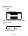
6.1.1 List of parameters
Choice of regulation type:
Speed Proportional: P
⇒ Proportional integral: PI
2
⇒ Proportional double integral: PI
Current regulation
In all cases
• Filtering frequency
• Offset
• Current limitation
Minimum value
20 Hz
- 3,4% V max.
0A
Maximum value
800 Hz
3,4% V max.
I pulse - drive
For speed regulation (P, PI, PI²)
• Maximum speed
100 rpm/min
100 000 rpm /min
• Speed for 1 V
10 rpm /min
14150 rpm /min
• Proportional gain
I pulse - drive /156
I pulse - drive x 210
• Integration stop
0,1 Hz
100 Hz
• Predictors (gravity, dry or dynamic friction, acceleration).
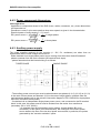
6.1.2 Regulation selection: current, proportional, PI, PI²
Current regulation
Choosing "current" means current can be controlled directly (therefore the motor torque through
the torque coefficient Kt). This then gives 10 V = pulse peak current of the drive selected
beforehand.
2
In this mode, PI/PI settings and predictors are neutralized. The only functions operative are:
Current limitation (often reduced below the permanent drive current, so as not to trip in mean or
rms values.
The second order low pass filter (filtering frequency), for reducing the effect of any resonance.
58
PVD 3530 GB 01/2005
DIGIVEX Little Drive Servoamplifier
Choosing P
The drive is used in a speed loop with purely proportional gain. This gain is the ratio between the
output current and the speed error. It is expressed in mA / rpm.
For the same current I, if the gain increases, the error ε is reduced, the rapidity of the system
increases as does its bandwidth.
An increase in gain may lead to instability because of the other components in the loop
(resonances, second order filter).
The use of proportional action P alone has the drawback of giving zero rigidity because there is
no integration ahead of the current section.
59
PVD 3530 GB 01/2005
DIGIVEX Little Drive Servoamplifier
Choosing PI (proportional and integral action)
Compared with P action alone, PI provides the following two modifications:
The gain (open loop) at zero frequency is infinite. If there is a torque surge, there will be an
angular discrepancy of the motor shaft compared with the state at rest. This angle will be
proportional to the torque applied and there will not be any permanent speed drift. The system
can be said to be "rigid". This rigidity is strictly proportional to the integration stop frequency.
The proportional gain P sets the bandwidth f0 (system rapidity). The integral action entails -90°
phase shift, which creates instability. This phase shift is not troublesome at low frequencies, but
may make the system unstable at higher frequencies. It is therefore best to adjust the "integral
stop frequency" correctly (0.2 - 0.3 times the bandwidth f0).
2
Choosing PI action (proportional and double integration)
2
Compared with P action alone, PI provides the following two modifications:
Rigidity when stopped is infinite. When motor torque surges and after a transient period, the
motor shaft returns to the position it was in at rest (there is no longer any permanent position
discrepancy).
The double integral action entails a -180° phase shift at low frequencies. Poor adjustment of the
integral stop frequency may entail instability in the system. Restrict to 0.1 to 0.2 times the
bandwidth f0.
60
PVD 3530 GB 01/2005
DIGIVEX Little Drive Servoamplifier
6.1.3 Integration stoppage
See the previous paragraph for the function of this parameter. Below is its definition after the
Bode graphs only (gain / frequency and phase / frequency).
Gradient-1
Gradient-2
6.1.4 Speed scaling
The choice of motor - drive combination determines the maximum possible speed. The
"Maximum" speed parameter can be used to reduce this maximum speed for the application. This
parameter is external to the speed loop and modifying it does not modify gain.
The "Speed for 1 Volt" parameter determines the speed "gradient" (e.g. maximum speed can be
obtained for 10 V, 9 V or 7 V, depending on the positioning control).
6.1.5 Filtering frequency
Resonance phenomenon
Many systems have one or more resonance frequencies related most of the time to mechanical
phenomena: inertia or mass, associated with the rigidity of the mechanical components (belts,
screws, reducing gear, frames, etc.).
In a zone of reduced frequency around the resonance frequency, there occurs:
Marked variations in loop gain.
Marked variations in the closed loop phase.
This leads to instabilities or "squeaking", with more or less violent oscillation.
61
PVD 3530 GB 01/2005
DIGIVEX Little Drive Servoamplifier
Second order filter
This phenomenon cannot be dealt with by P/PI/PI2 adjustment. If the resonance cannot be dealt
with mechanically, the frequencies concerned must be eliminated. This is the function of the
second order low pass filter.
Diggb17.D/pl35.W
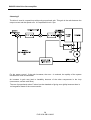
6.1.6 Predictors
Purpose of predictors
Four physical phenomena:
Vertical mass.
Dry friction
Friction proportional to speed.
Acceleration.
Are direct and calculable causes of modification of motor torque.
The purpose of the predictors is, by calculation, to act directly on the current set point, without
recourse to the speed loop and without waiting for the speed error produced by these
phenomena (see block diagram).
The principle of predictor setting and work is to minimize the current set point part from the P, PI,
2
PI branch and therefore to reduce the speed error.
As these predictors are outside the speed loop (which must be adjusted first), they do not affect
stability. They provide an appreciable improvement on response time.
The acceleration predictor improves stability and allows gain to be increased in any position loop
superimposed on the speed loop.
However, it should be noticed that many speed servocontrols do not require the use of these
predictors.
62
PVD 3530 GB 01/2005
DIGIVEX Little Drive Servoamplifier
General characteristics of each predictor
Mass or gravity compensation (vertical axis)
The current value, in amps, required by the motor to move the mass at constant speed (average
between up and down) is introduced directly into the parameter.
Dry or "static" friction
The friction force is fixed, whatever the speed. Its direction is opposed to motion, the sign
therefore depends on the speed set point sign.
In this case too, the values are entered directly in amps, for the required motor current to
overcome friction.
The "threshold" expressed in rpm defines a speed "band" within which this compensation is zero.
The threshold is of the order of 1/1000th of maximum speed. This zone allows torque oscillation
to be reduced during rapid and repeated changes of the speed sign. This is the case, in
particular, at rest when there is a position loop.
"Dynamic" friction compensation
Friction proportional to speed, encountered on some mechanical components using fluids.
Value to enter: coefficient in amps / rpm.
Acceleration prediction
Depending on the total inertia (load and motor rotor) and on the desired acceleration, the torque
necessary is equal to: C = ΣJ . dω / dt.
The set point is monitored therefore in order to send a set point that is proportional to inertia
(fixed) and to acceleration to the current control. This is one of the limits of the system; there is
no point in having a variation in the speed set point that is greater than the maximum possible
acceleration of the motor, given by dω / dt = peak torque / ΣJ. Acceleration prediction is only
useful if there is a ramp on the speed reference.
The parameter used is tpr, prediction time, in milliseconds; tpr can vary between:
0 ms (no prediction)
t = td, start up time from 0 to maximum speed, with full drive current. There is then 100%
correction.
63
PVD 3530 GB 01/2005
DIGIVEX Little Drive Servoamplifier
6.2 Inputting Parameters
Customization parameters for the motor - amplifier unit are entered on start-up, using a PC with
the PME software, under WINDOWS.
The transition of this customization to a different calibre amplifier leads to the generation of a
fault. The parameters contained in the EEPROM are saved.
6.3 Setting with DIGIVEX PC Software
6.3.1 Outline
SELECT MOTOR/DRIVE COMBINATION
SELECT TYPE OF REGULATION
CURRENT
SPEED (P/PI/PI=)
CURRENT LIMITATION,
SECOND ORDER FILTER, fc
POSSIBLE SETTINGS
Max. Speed, Current limitation,
Speed for 1 Volt
NO PREDICTOR
FILTER fc & PROPORTIONAL GAIN P
ADJUSTMENT
(suppress resonance)
ENTER PI OR PI=
Set integral stop frequency
GRAVITY AND DRY FRICTION
PREDICTORS
DYNAMIC FRICTION AND
ACCELERATION PREDICTORS
64
PVD 3530 GB 01/2005
DIGIVEX Little Drive Servoamplifier
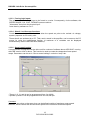
6.3.2 internal variables
Accessible internal variables (via DIGIVEX PC software)
The following internal variables may be selected:
9
8
7
6
1
2
3
4
10
5
11
12
Reference
♦
♦
♦
♦
♦
♦
♦
♦
♦
♦
♦
♦
1
2
3
4
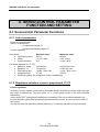
5
6
7
8
9
10
11
12
Input set point in rpm
Speed measurement in rpm
2
P, PI, PI output in Amps
Sum in Amps
Current set point in Amps
Acceleration in ms
Viscous friction in Amps
Dry friction in Amps
Pesenteur in Amps
Position in degrees
Phase current U in Amps
Phase current W in Amps
The 4 selected variables are chosen from the list of variables.
65
PVD 3530 GB 01/2005
DIGIVEX Little Drive Servoamplifier
Access via the name of the variable, this is valid for the 16 above plus the following variables:
•
•
•
•
•
•
•
•
• Auxiliary input in Volts
LF generator
Position – filtered in degrees
Speed – filtered
DLD thermal load
Motor thermal load
Recovery thermal load
Temperature in °C
Bus voltage in Volts
Active I in Amps
Reactive I in Amps
Id current in Amps
Iq current in Amps
Ud voltage in Volts
Uq voltage in Volts
It should be noticed that these variables can be assigned to the two analog outputs, which
means a separate oscilloscope can be used.
6.3.3 Entering parameters via DIGIVEX PC software
See DIGIVEX PC software instructions:
Choice of rating
Choice of motor (standard or special)
Choice of resolver
Entering servo-control parameters (global transfer)
Assigning inputs / outputs and variables
Use of the oscilloscope function
Use of stimuli function
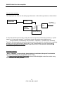
6.3.4 Setting loop parameters for speed regulation
This can be done by using the "Setting Assistant" menu or directly with the stimuli and
oscilloscope.
Speed for 1 V and maximum speed
The maximum possible speed is set when the motor - drive choice is made.
It can be reduced only here:
Choose a "dc" stimulus of, say, 1 volt.
Check the value obtained for the "measure speed in rpm" variable using the variable observation
or oscilloscope functions.
66
PVD 3530 GB 01/2005
DIGIVEX Little Drive Servoamplifier
Proportional gain adjustment
Initial status
Switch to proportional gain P alone.
Filtering frequency fc to maximum (800 Hz) and low gain.
System ready to run, no predictor.
Proportional gain and filter frequency are adjusted simultaneously. If, by increasing proportional
gain, the system starts to resonate, the resonance must be eliminated by reducing the filter
frequency, then increasing P, etc. until a compromise is found.
Maximum recommended for P.
There is a maximum advisable proportional gain, depending on the drive rating, and
corresponding to maximum current oscillation.
RATING
P In mA/ rpm
2/4
4/8
35
75
7,5/15
150
N.B. This gain may be exceeded under certain circumstances. Please ask for details.
Generate a speed set point scale (0.5 to 1 V).
Use the oscilloscope function to display
Channel 1 ⇒ the input set point
Channel 2 ⇒ the speed measurement
Trigger on channel 1 at 5 or 10 percent of N max, leading edge.
Increase gain P
The stimulus is excited on line. The response is collected at one scale of speed set point.
67
PVD 3530 GB 01/2005
DIGIVEX Little Drive Servoamplifier
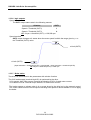
There are three possibilities :
Non oscillating response
A response must be obtained without overshooting and oscillation. For example, increase gain
until oscillations gradually appear, then reduce it by 20 to 30%.
If the maximum value shown in the table is reached with P gain, without reducing the filtering
frequency, then:
Stop increasing P
Reduce the filtering frequency until the limit of oscillation
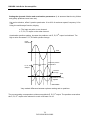
Filtering frequency setting
Oscillations may appear on the response obtained above (even when speed is increasing).
Response with pseudo-oscillation
This gives frequency resonance (probably mechanical origin) fr = 1/T, greater than 100 Hz.
68
PVD 3530 GB 01/2005
DIGIVEX Little Drive Servoamplifier
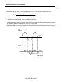
Then reduce the filtering frequency until the oscillation disappears almost completely. If that
cannot be done, the maximum gain is reached.
If possible, gain can be increased again until a response is obtained without oscillation.
Oscillation may reappear. Reduce the filtering frequency a little more.
Notice that it is essentially P and filtering frequency that determine the bandwidth.
If the resonance frequency is too low, adjust the filter frequency to a high value.
PI/PI2 - integral stop frequency setting
Initial status
P gain alone. P and filtering frequency setting completed.
Integration stop frequency = 0.
Still no integration.
System ready to run.
♦ Select PI or PI².
♦ Use the same stimulus as before (index analysis).
♦ "On line", increase the integration stop frequency until overshoot is obtained in
the order of:
+ 25 - 30% in PI
+ 15 - 20% in PI²
Without oscillation.
If the frequency is too high, fairly low frequency oscillations occur (< 50 Hz). Frequency must
then be reduced (never readjust P gain).
Speed
measurement
fi too high
pseudo-period
Time
Dipl43gb.D/45W
69
PVD 3530 GB 01/2005
DIGIVEX Little Drive Servoamplifier
Speed
measurement
fi too high
pseudo-period
Time
Dipl43gb.D/46W
2
Do not change PI to PI without setting the integral frequency to 0.
6.3.5 Setting predictors
Initial conditions
All loop parameters (P, integral and filtering frequency, max. speed, current limitation) are set
(without predictors).
The system is ready to run.
Setting the Gravity and Static Friction predictors
Notice that the gravity factor is zero for a horizontal axis.
Take a square stimulus, offset = 0, peak to peak value = 3 to 5% of maximum speed in rpm,
frequency 0.2 to 1 Hz.
Using the oscilloscope function, display:
♦ The input set point,
♦ The current set point.
70
PVD 3530 GB 01/2005
DIGIVEX Little Drive Servoamplifier
Input
reference
Time
Current
reference
Time
Diggb43.D/47W
N.B. I+ and I- are to be taken with their sign. In general I- is negative.
In principle:
I+ + I−
in Amps (horizontal motion, gravity = 0).
2
I −I
Static friction = + - in Amps.
2
Gravity =
Enter these values into the parameters.
Enter the threshold value (e.g. threshold = max. speed / 1000).
After introducing the values, the result obtained can be checked with the same stimulus.
Check the input set point on one channel and the P, PI, PI2 output on the other channel. This
should give a result close to:
P, PI, PI≤
Output
Time
71
PVD 3530 GB 01/2005
DIGIVEX Little Drive Servoamplifier
Setting the dynamic friction and acceleration parameters. (It is assumed that the dry friction
and gravity predictors have been set).
Use a sine stimulus, offset 0, peak to peak value 10 to 20% of maximum speed, frequency 0.2 to
1 Hz.
Using the oscilloscope function, display:
♦ The input set point on one channel.
♦ P, PI, PI² output on the other channel.
Acceleration predictor setting. Increase the predictor until P, PI, PI2 output is minimized. Too
high a value increases P, PI, PI2 with a phase change
Input
reference
Time
P, PI, PI=
Output
Predictor too weak or
zero
Maximum positive
acceleration
Predictor
too high
Time
Predictor correctly
adjusted
DIGPL43.D/
49.W
Very marked difference between optimum setting and no predictor
2
The correct setting corresponds to minimum amplitude P, PI, PI output. The predictor must allow
2
the P, PI, PI output to be reduced in a ratio of at least 5 to 10.
72
PVD 3530 GB 01/2005
DIGIVEX Little Drive Servoamplifier
Remember that the value of tpr (prediction time) (in ms) is close to td (start up time) with:
td =
(Load inertia + motor inertia) . ω max
Max torque
td is the acceleration time from 0 to maximum speed with maximum torque,
td in seconds, inertia in kgm2, max. ω in rd/s, torque in Nm
Setting the dynamic friction predictor. Once all the other predictors have been adjusted, increase
the dynamic predictor to minimize the P, PI, PI² output signal.
When the setting is correct, this output should be minimum and in phase with the input set point.
Input
reference
Time
P, PI, PI=
Output
Time
Minimum value
DIGPL43.D/50.W
73
PVD 3530 GB 01/2005
DIGIVEX Little Drive Servoamplifier
6.3.6 Setting current regulation parameters
If the "current" option has been chosen, the only adjustments needed are:
Current limitation; take care in this type of application that it does not trip with mean or rms
current monitoring. Current limitation is often equal to permanent current.
Second order filter frequency. This can only be done with the "superior" regulation loop giving the
current set point.
6.3.7 Other characterization parameters
Logic and analog inputs / outputs
Access via:
I/O, servo-control parameter adjustment function.
This means that it is possible to:
assign one of the internal variables to each of the two 10 V analog outputs.
assign a constant value (up to -12V and +12V) to the analog outputs
force the logic inputs to 0 or 1.
The logic inputs / outputs are assigned permanently.
Encoder emulation
Choice of number of marks between 1 and 16384 per turn (off line).
Validating by teaching of zero mark position (on line).
Miscellaneous choices
Choice of processing strategy for monitoring of mean or rms currents: current reduction or power
opening.
Choice of brake strategy: current reduction or not in the event of brake closure.
Choice of user strategy for thermal protection of motor (with or without thermal protection).
(See PME MODULE DIGIVEX Little Drive PVD 3536 manual)
74
PVD 3530 GB 01/2005
DIGIVEX Little Drive Servoamplifier
7. COMMISSIONING - SERVO-CONTROL PARAMETER
SETTING - DETECTING REASONS FOR STOPPAGE
7.1 Start-up Sequence
7.1.1 Preliminary checks
Wiring check
Power and auxiliary connections to DLD.
Reset wiring.
External 24 V supply for brake.
Check the resolver connections.
♦ Motor end
♦ DLD end
Check the power, brake and thermal connections.
♦ Motor end
♦ DLD end
Supply type check
Power: 50/60 Hz, 230 V single or three-phase
Auxiliaries: single-phase 50/60 Hz, 230 V.
Brake supply: 24 V dc ±10% (including oscillation).
Caution: Before doing any work on the system, make sure the power bus is at 0 V. Wait at least
three minutes after the motors have come to a complete stop before starting work. Wait for the
7-segment display to go off.
7.1.2 Commissioning with DIGIVEX PC software
Connect the PC via the RS232 serial link.
Energize the auxiliary parts (low levels) alone; 0 is displayed
Go "On line" via the PC, with the PC in interactive mode. Parameter adjustment functions'
connection. If this connection is not carried out:
♦ Check the compatibility of the serial link configuration (PORT, BAUD RATE, etc.)
♦ Check the serial link cable.
♦ Check that you are using the correct interface (DIGIVEX, DLD).
75
PVD 3530 GB 01/2005
DIGIVEX Little Drive Servoamplifier
Once "on line" all the parameters in the DIGIVEX Little Drive can be read.
Using the PC help functions, check the fault analysis for the lack of faults.
Check the SPEED, RANGE, CW, CCW, TORQUE input status.
Then configure the amplifier. This can be done "off line" in a file and then transferred or modified
"on line".
♦ Choice of motor.
♦ Choice of servo-control parameters (without the power part, their validity cannot
be checked).
♦ Ancillary checks: validate brakes, analog outputs, safety strategy, etc...
Use the software to force the drive to zero torque.
Power up. 1 is displayed.
Remove "zero torque" locking using the software or via hardware contact (set "TORQUE" input
at 24V)
Carry out system adjustment using stimuli.
♦ "dc" stimuli (square with peak-to-peak = 0). Check max. N.
♦ "Square" stimuli or setting procedure for adjusting servo-control parameters.
♦ DIGIVEX PC software for setting the predictors if necessary.
Check the driven mechanism can operate freely.
7.2 Detecting Reasons for Stoppage
7.2.1 Fault display - drive function
Incidents with drive operation can be displayed in two ways.
•
•
On the 7-segment display situated on the front panel of the amplifier
Via the software which indicates in uncoded language the nature of the problem and
gives advice on corrective action.
76
PVD 3530 GB 01/2005
DIGIVEX Little Drive Servoamplifier
7.2.1.1 Handling operational malfunctions
There are 2 kinds of malfunction:
• Malfunctions that require stoppage of the system
These malfunctions must lead to:
♦ The opening of the main contactor and disconnection of the power supply
(controlled by the DRV OK X2/6, X2/18 logic output) (See § 5.2)
♦ The fault is stored in the axis and the data is displayed on the front panel.
Malfunction leading to a reduction in the system's dynamic characteristics.
♦ For excessive DLD dissipater temperature.
♦ For excessive mean drive current or excessive rms motor current, if the drive
parameter setting allows operation to continue. The choice of continuing
operation with reduced current or stopping is made by the "current protection"
strategy in the "servo-control" window of the parameter setting software.
These malfunctions lead to:
♦ A reduction in the motor current
♦ The data being displayed on the front panel (7-segment display flashes).
7.2.1.2 Current monitoring
Mean drive current
To prevent the motor thermal tripping by the thermal sensor, the drive monitors the rms
current [I2 = f(t)].
The rms current is compared to the permanent permissible current at slow rotation by the
motor Î0 (after first order filtering following motor time constant). This data, which is
characteristic of the motor, is known to the drive when the choice of motor - drive is
made.
As before there is a choice between two strategies:
♦ Strategy 1: Stoppage due to the "DRV OK" output shifting to logic 0 which must
induce the opening of the main contactor
♦ Strategy 2: Reduction of the pulse current at 0.9 Î0 motor. The 7-segment display
flashes.
77
PVD 3530 GB 01/2005
DIGIVEX Little Drive Servoamplifier
Drive output current
There are two forms of monitoring:
♦ Short-circuit protection: monitoring of current drift.
♦ Excessive output current (maximum current). Check whether the current as
measured exceeds the drive pulse current by 30%.
In both cases, there is stoppage due to the "DRV OK" output shifting to logic 0 which
must induce the opening of the main contactor.
7.2.1.3 Temperature monitoring
DIGIVEX Little Drive dissipater temperature
♦ If the temperature is less than 85°C at the dissipater, nothing happens.
♦ Between 85 and 109°C, there is a reduction in the pulse current which can
release the ("7-segment" display flashes at low frequency).
♦ At 110°C, stoppage of the amplifier
Servo-motor winding temperature
Each motor has a thermal sensor. When customizing the drive, this sensor can be
taken into account or ignored. If it is taken into account (usual case), excessive motor
temperature causes a fault.
Ambient temperature
This is measured between the electronic boards and operations are stopped when it
exceeds 60°C.
7.2.1.4 Monitoring the DC Bus voltage
Recovery fault:
Motion controller electrical breaking capacity needs updating, cycle too restricting.
Bus overvoltage
Motion controller breaking capacity much too low with regard to the application.
7.2.1.5 Other monitoring
No resolver
Resolver fault or wiring fault.
Overspeed
Speed > 1.15 times the maximum motor - drive setting.
These two cases entail a fault with:
Data displayed on the 7-segment display
78
PVD 3530 GB 01/2005
DIGIVEX Little Drive Servoamplifier
7.2.1.6 7-segment display
Function: to provide information on DLD status discriminating between faults.
Description :
Display
0
1
2
3
3 Flashing
4
6
7
7 Flashing
8
9
. (dot)
F
r
PC SOFTWARE FAULTFINDING
Max. drive current reached
Excessive mean current
Excessive rms current
Excessive motor temperature
Excessive dissipater
temperature
Excessive ambient temperature
Resolver fault
Excessive speed
CPU fault
Bus overvoltage
Motor not connected
Liaison impossible
Excessive mean
current
Excessive rms
Current
Excessive dissipater
temperature
Description
Drive live, no power present
Drive OK, power present
Resolver fault
Excessive ambient temperature or dissipater temperature
Excessive dissipater temperature / current reduction
Excessive speed
Maximum drive current reached
Excessive mean current or excessive rms current
Excessive mean current or excessive rms current: Reduction
Bus overvoltage
Excessive motor temperature
CPU fault
Back-up error
Recovery fault
COMMENTS
Output or earth short circuit
Too much current asked of drive
Too much current asked of drive. Cycle too demanding.
Cycle too demanding or no motor fan cooling
Fan cooling stopped or excessive cabinet temperature
Problem with resolver or wiring
Speed reference > 10 V +15%
or speed parameter setting error
Regenerative braking impossible.
Disconnected from mains supply.
Motor wrongly connected
No power supply
Current reduction.
I mean > drive rating
Current reduction.
Drive RMS current > Îo motor
Max. current reduced depending on temperature
79
PVD 3530 GB 01/2005
DIGIVEX Little Drive Servoamplifier
7.2.1.7 Corrective actions
The incidents that may arise (from wiring errors or mishandling) are as follows:
Resolver fault
♦ Check the resolver connection.
Overcurrent
♦ poor motor connection (motor phase missing)
♦ programmed motor does not correspond to connected motor
Overspeed
♦ Nmax. incorrectly set
♦ Accidental transition to torque regulation
Motor fails to run and remains without torque
♦ System is set to zero torque (hardware or software input TORQUE =0). The
torque has been forced to zero during a global transfer. Reset system torque
(see software).
♦ The motor is not connected.
Motor fails to run, but torque present
♦ CW and CCW inputs set to zero (hardware or software). Check with software.
80
PVD 3530 GB 01/2005
DIGIVEX Little Drive Servoamplifier
7.3 Defaults description
DEFAULT
2
TYPE
Resolver fault
Excessive
ambient
3
or
dissipater
temperature
4
Excessive
speed
6
Maximum motion
controller current
reached
ACTION
Detection of S1,S2, S3 and S4 signal absence.
Loss of resolver excitation: Veff rated value = 7V, Frequency = 8012 Hz on R1, R2/R3.
Loss of sin (S2 S4) or cos (S1 S3) signals or too low resolver transformation ration.
Bad contact (check connectors).
Ambient: this is measured between the electronic boards and operations are stopped when
the temperature exceeds 60°C
Dissipater:
If the temperature is less than 85°C: nothing happens
85°C < T< 109°C: there is a progressive reduction of current authorized by the motion
controller.
110°C < T: operations stop.
Can be linked to large braking cycles.
Check:
• Electrical control cabinet ventilation
• Good circulation around the motion controller
Rotation speed measured at more than 15% above the maximum application speed
Check:
• Motion controller customization inappropriate to the motor and/or the application
• Speed instruction more than 15% above the maximum authorized value.
• Driving load
The measured current exceeds the motion controller’s pulse current by 30%.
Check:
• Long length of cable
• Use of shielded cable with large capacity per unit length
• The motor programmed in the motion controller does not correspond to the
connected motor
81
PVD 3530 GB 01/2005
DIGIVEX Little Drive Servoamplifier
DEFAULT
7
TYPE
Excessive mean
or
rms
current
8
Bus overvoltage
9
Excessive
motor
temperature
r
Recovery fault
ACTION
Mean current: measurement of the mean current supplied by the motion controller
Rms current: calculation of the rms current supplied by the motion controller
Causes:
• Oversized operating cycle
• Mechanical binding spot
Braking recovery impossible
Causes:
• Oversized operating cycle
• Motion controller braking capacity much too low with regard to the application
Causes:
• Check connections
• The motor is confined and cannot cool down
• Motor does not have a temperature sensor: this sensor was not acknowledged during
customization.
Causes:
• Cycle too restricting
• Axis recovery capacity exceeded.
82
PVD 3530 GB 01/2005
DIGIVEX Little Drive Servoamplifier
8. APPENDIX
UL CERTIFICATE
83
PVD 3530 GB 01/2005