1
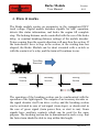
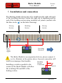
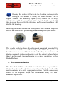
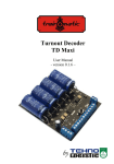
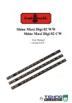
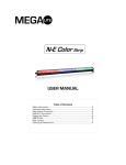
Brake Module
User Manual
- version 0.0.1 -
by
Barke Module
User Manual
Version
0.0.1
© Copyright 2013 Tehnologistic SRL
All rights reserved
No part of this publication may be reproduced or transmitted in any
form or by any means, electronic or mechanical, including
photocopying, without the written permission of
SC Tehnologistic SRL
Subject to technical modification
Please read this manual carefully before carrying out the
installation!!! Although our products are very robust, incorrect
wiring may destroy the module!
During the operation of the device the specified technical parameters
shall always be met. At the installation the environment shall be fully
taken into consideration. The device must not be exposed to moisture
and direct sunshine.
A soldering tool may be necessary for the installation and/or
mounting of the devices, which requires special care.
During the installation it shall be ensured that the bottom of the
device should not contact with a conductive (e.g. metal) surface!
Content
1.
2.
3.
4.
5.
6.
7.
Features ....................................................................................... 3
Package Content .......................................................................... 3
Tehnical parameters .................................................................... 3
How it works ............................................................................... 4
Installation and connection .......................................................... 5
Recommandation ......................................................................... 6
Notes ............................................................................................ 7
Page 2 of 8
Barke Module
User Manual
Version
0.0.1
1. Features
- usable in DCC systems with mobile decoders that support the ABC
- exact stopping in front of signals
- free passage in the opposite direction
- exact stopping in front of signals
ordercode tOm 02060401
2. Package Content
The tOm Brake Modules are supplied in transparent plastic bags or
blister packs. Check when unpacking the product if the following
parts are present: 1 x tOm Brake Module, 2x screws, 2x plastic
spacers.
3. Tehnical parameters
- maximum current carrying capacity
1A continuous
- Size LxWxH: mm x mm x mm
Page 3 of 8
Barke Module
Version
0.0.1
User Manual
4. How it works
The Brake module creates an asymmetry in the symmetrical DCC
track voltage. Digital mobile decoders capable for ABC operation,
detects this status information, and brake the engine till complete
stop. The braking distance can be controlled with the use of the brake
delay, or constant breaking distance settings of the mobile decoder.
Trains coming from the oposite direction will pass thru the section. If
the train doesn’t have to stop in the section, or the waiting time has
elapsed, the Brake Module can be short circuited with a switch or
with the contacts of a relay, and the train will continue to run.
Travelling
Direction
Driving
Section
Breaking
Section
Driving
Section
The operation of the breaking section can be synchronized with the
operation of the light signals. The outputs of an accessory decoder or
the signal decoder itself can drive a relay and the breaking section
can be activated in case of red signal (train stops), or deactivated in
the case of green signal (train passes thru, or start to run). Some
signals have auxiliary contacts which can be used for the same
purpose. The breaking section has to dimentioned in such a way, that
the fastes train should be able to stop within this length.
Page 4 of 8
Barke Module
Version
0.0.1
User Manual
5. Installation and connection
The Braking module always has to be installed on the right side track
of the travelling direction. Isolate the right rail at beginning and the
end of the breaking section using insulated rail joiners (marked with
the blue circles
on the below drawing).
Driving
Section
Breaking
Section
DCC
Track
Signal
Driving
Section
Travelling
Direction
The Brake Module is an assymetrical device, please connect it
as it is illustrate in the picture above. Incorect connection will
result in an improper functionality.
Breaking
Installing a switch in parallel to the
contact of the Break Module will allow
the switching ON and OFF of the
braking section.
Section
Connection
Switch
Page 5 of 8
Barke Module
User Manual
Version
0.0.1
Opening the switch will activate the breaking section, while
closing it will disable it. Using the Brake Module with a
signal, connect the normally open (NO) contact of a relay
synchronized with the green light of the signal. As the signal will
turn to green, the relay will be activated, and closing its contacts will
disable the breaking.
Installing the Brake Module on the layout is done with the supplied
screws and spacers. For positioning and mounting see figure below:
The diodes inside the Brake Modul supports a nominal current of 1A
in continuous mode but can withstand to peaks of 30A for a period of
8 miliseconds. In case of short circuit on the line, the protection of
digital command stations or boosters cuts the output voltage faster
than 8 milliseconds, thus performing as a circuit protection for the
Brake Modules.
6. Recommandation
The tOm Brake Modules should be installed as close as
the track sections; the electrical connections should be
multi-conductor wire with appropriate section. Cut the
strictly to the required length. We recommend using
diameter copper wire.
possible to
made with
conductors
0.25 mm2
Page 6 of 8
Barke Module
User Manual
Version
0.0.1
7. Notes
Page 7 of 8
Barke Module
User Manual
Version
0.0.1
Copyright © 2013 Tehnologistic SRL
All rights reserved
The information in this document is subject to change without
notice
“train-o-matic” and the
logo are registered
trademarks of SC Tehnologistic SRL
www.train-o-matic.com
www.tehnologistic.ro
ABC Technology is registered trademark of Lenz Elektronik
http://www.digital-plus.de
Tehnologistic SRL
Str. Libertatii Nr. 35A
407035 Apahida, Cluj
Romania
Tel +40-264-556454
Fax +40-264-441275
Page 8 of 8